Banner Q5X Instruction Manual
Laser triangulation sensor with analog outputs and iolink
Hide thumbs
Also See for Q5X:
- Instruction manual (61 pages) ,
- Quick start manual (17 pages) ,
- Manual (15 pages)

Related Manuals for Banner Q5X


Summary of Contents for Banner Q5X
- Page 1 Q5X Laser Triangulation Sensor with Ana log Outputs and IOLink Instruction Manu Original Instructions p/n: 219602 Rev. C June 22, 2023 © Banner Engineering Corp. All rights reserved.
-
Page 2: Table Of Contents
Contents Contents ..........................2 Chapter 1 Product Description Models .......................................... 5 Overview ........................................5 Class 2 Laser Description and Safety Information ............................6 Features ........................................7 Display and Indicators ................................... 7 Buttons ........................................7 Chapter 2 Installation Sensor Orientation......................................9 Mount the Device......................................10 Wiring Diagrams ......................................10 Cleaning and Maintenance .................................. - Page 3 Chapter 7 Accessories Cordsets ........................................51 Brackets........................................52 Reference Targets ..................................... 53 RSD1 Remote Display....................................54 Chapter 8 Product Support and Maintenance Troubleshooting ......................................55 Contact Us ........................................55 FCC Part 15 Class A ....................................55 Industry Canada Class A .................................... 56 Banner Engineering Corp Limited Warranty .............................. 56 ............................................. 56...
- Page 4 Blank page...
-
Page 5: Chapter 1 Product Description
(420mA) Overview The Q5X Laser Triangulation Sensor offers analog and discrete (switched) outputs with IOLink. The normal sensor state is Run mode. From Run mode, users may change the switch point value and channel selection and perform the selected TEACH method. -
Page 6: Class 2 Laser Description And Safety Information
Q5X Laser Triangulation Sensor With Analog Outputs And IO-Link Instruction Manual Class 2 Laser Description and Safety Information CAUTION: • Return defective units to the manufacturer. • Use of controls or adjustments or performance of procedures other than those specified herein may result in hazardous radiation exposure. -
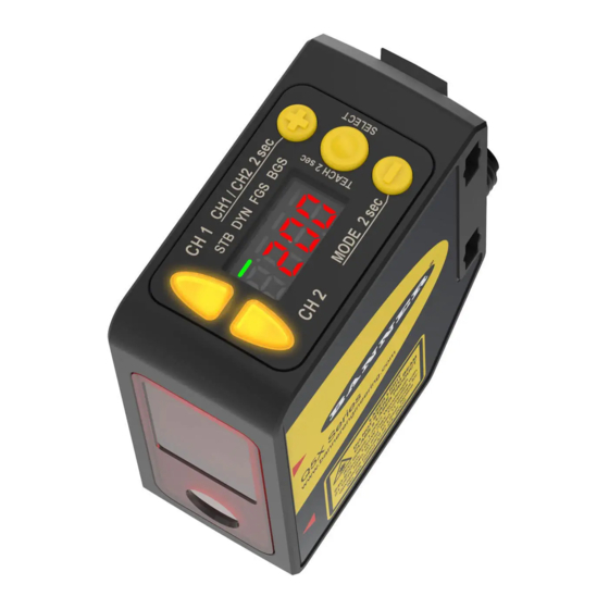
Page 7: Features
Q5X Laser Triangulation Sensor With Analog Outputs And IO-Link Instruction Manual Features The Q5X Laser Triangulation Sensor has three major features. Q5X Features Two output indicators (amber) Display Buttons Display and Indicators The display is a fourdigit, sevensegment LED. Run mode is the primary view displayed. - Page 8 Q5X Laser Triangulation Sensor With Analog Outputs And IO-Link Instruction Manual Q5X sensor face (+)(CH1/CH2) (SELECT)(TEACH) • Press to navigate the sensor menu in Setup mode • Press to select menu items in Setup mode • Press to change setting values; press and hold to in...
-
Page 9: Chapter 2 Installation
See the following figures for examples of correct and incorrect sensor-to-target orientation as certain placements may pose problems for sensing some targets. The Q5X can be used in the less preferred orientation and at steep angles of incidence and still provide reliable detection performance due to its high excess gain. For the minimum object separation distance re... -
Page 10: Mount The Device
Q5X Laser Triangulation Sensor With Analog Outputs And IO-Link Instruction Manual Continued from page 9 Orientation for a color or luster difference Orientation for highly reflective target (Optimal) Reflective Horizontal Surface (optional) Orientation Orientation Mount the Device If a bracket is needed, mount the device onto the bracket. -
Page 11: Button Map From Rsd1 To Sensor
Q5X Laser Triangulation Sensor With Analog Outputs And IO-Link Instruction Manual Button Map from RSD1 to Sensor The sensor may be optionally connected to the Banner RSD1 remote display accessory. Refer to this table for the RSD1 but ton association with your sensor. - Page 12 Blank page...
-
Page 13: Chapter 3 Sensor Programming
Q5X Laser Triangulation Sensor With Analog Outputs And IO-Link Instruction Manual Chapter Contents Channel 1 and Channel 2 (CH1/CH2) ................................13 Setup Mode ........................................13 Manual Adjustments ......................................34 Remote Input........................................34 Locking and Unlocking the Sensor Buttons............................... 36 Button Instructions......................................36 Remote Input Instructions .................................... - Page 14 Q5X Laser Triangulation Sensor With Analog Outputs And IO-Link Instruction Manual Sensor Menu Map—Channel 1 June 22, 2023 © Banner Engineering Corp.
- Page 15 Q5X Laser Triangulation Sensor With Analog Outputs And IO-Link Instruction Manual Sensor Menu Map—Channel 2 June 22, 2023 © Banner Engineering Corp.
-
Page 16: Teach Procedures (Analog)
Q5X Laser Triangulation Sensor With Analog Outputs And IO-Link Instruction Manual TEACH Procedures (Analog) Use the following procedures to teach the Ch1 analog output. To cancel a TEACH procedure, press TEACH for longer than 2 seconds, or hold the remote input low for longer than 2 sec... - Page 17 Q5X Laser Triangulation Sensor With Analog Outputs And IO-Link Instruction Manual Method Action Result Push Button Present the second target. The sensortotarget distance must be with SEt and 10 U flash alternately on the in the sensor's range. display. The 2Pt indicator flashes.
-
Page 18: Teach Mode (Discrete)
Q5X Laser Triangulation Sensor With Analog Outputs And IO-Link Instruction Manual Continued from page 17 Method Action Result Remote Input No action is required. Teach the sensor the 5 V (12 mA) midpoint. Method Action Result Push Button Press TEACH to teach the target. - Page 19 Q5X Laser Triangulation Sensor With Analog Outputs And IO-Link Instruction Manual Method Action Result SEt and 1St flash alternately on the dis Push Button Press and hold TEACH for longer than 2 seconds. play. The 1-Pt and 2-Pt indicators flash.
- Page 20 Q5X Laser Triangulation Sensor With Analog Outputs And IO-Link Instruction Manual Dynamic Background Suppression The sensor must be set to tch = dYn to use the following instructions. The DYN indicator is amber to indicate Dynamic TEACH mode. To program the sensor using remote input, remote input must be enabled (out2 = SEt).
- Page 21 Q5X Laser Triangulation Sensor With Analog Outputs And IO-Link Instruction Manual Continued from page 20 Method Action Result Remote Input Singlepulse the remote input. Expected TEACH Behavior for Dynamic Background Suppression Condition TEACH Result Display Two valid distances that are greater than or The switch point distance flashes on the dis...
- Page 22 Q5X Laser Triangulation Sensor With Analog Outputs And IO-Link Instruction Manual Method Action Result Light Operate SEt and on flash alternately on the dis play. The 1-Pt and 2-Pt indicators flash. Push Button Press and hold TEACH for longer than 2 seconds.
- Page 23 Q5X Laser Triangulation Sensor With Analog Outputs And IO-Link Instruction Manual The sensor must be set to tch = bGS to use the following instructions. The BGS indicator is amber to indicate Background Suppression mode. To program the sensor using remote input, remote input must be enabled (out2 = SEt).
-
Page 24: Loss Of Signal (Los)
Q5X Laser Triangulation Sensor With Analog Outputs And IO-Link Instruction Manual Dual TEACH (Channel 2 only) Present the target. Method Action Result Push Button Present the reference target. The target's match percentage displays Remote Input Start the TEACH mode. Method... -
Page 25: Input Wire Function (Inpt)
Q5X Laser Triangulation Sensor With Analog Outputs And IO-Link Instruction Manual Analog output value during a loss of signal Option Description The Analog Output switches to this value 2 seconds after a loss of signal. When advanced 0 V (4 mA)—default measurements are enabled, the Analog Output is updated to this value immediately upon the release of the trigger input. -
Page 26: Slope (Slpe)
Q5X Laser Triangulation Sensor With Analog Outputs And IO-Link Instruction Manual Continued from page 25 Trigger Submenus Description The difference between the maximum and minimum distance since the last trigger event. For additional in Range rnGE formation on the Range measurement behavior when the maximum or minimum distance is outside of the taught values, see "... -
Page 27: Output (Out2)
Q5X Laser Triangulation Sensor With Analog Outputs And IO-Link Instruction Manual • nEG—the slope is negative Slope—Voltage Sourcing Models Slope—CurrentSourcing Models Positive Positive Slope Slope Near Near Window Window Window Window Target Position Target Position The analog voltage output tracks slightly beyond the upper window limit (up The analog current output tracks slightly beyond each window limit (from to 10.2 V) -
Page 28: Window Size (Und2)
Q5X Laser Triangulation Sensor With Analog Outputs And IO-Link Instruction Manual ON enables the Adaptive Tracking Algorithm at the standard speed—Recommended for many applications detecting low contrast targets. Standard adaptive tracking adjusts the thresholds around slowly changing background and environmental conditions. -
Page 29: Output Timing Delays
Rate (ms) When lateral entry needs to be considered, the lateral entry response is added to calculate the total response time. NOTE: The Q5X uses a dynamic measurement rate, so these response times are worstcase. Output Timing Delays Use this menu to select the output timing delay to be set. - Page 30 Q5X Laser Triangulation Sensor With Analog Outputs And IO-Link Instruction Manual Output Timing Delays Output OFF Delay ON Delay 1-Shot Time (D = 1ms - 90.0s) When one of the timing delay options is chosen, the sensor returns to the Setup menu and additional options become avail...
-
Page 31: Hysteresis (Hys2)
Q5X Laser Triangulation Sensor With Analog Outputs And IO-Link Instruction Manual Hysteresis (hYS2) Use this menu to set the hysteresis distance around the switch point. Auto (The sensor automatically selects a recommended minimum hysteresis distance relative to the current switch point dis... -
Page 32: Shift The Zero Reference Location After A Teach (Shft)
Q5X Laser Triangulation Sensor With Analog Outputs And IO-Link Instruction Manual —0 is the front of the sensor and the measurement increases further from the sensor. —0 is the maximum range and the measurement increases closer to the sensor. Shift the Zero Reference Location after a TEACH (ShFt) Use this menu to select whether the sensor shifts the zeroreference location based on the last TEACH process. -
Page 33: Offset (Ofs1 Or Ofs2)
Values increase or decrease by up to 291 cm for 3000 mm models. For BGS mode, the default is Auto because the Q5X automatically selects where to position the switch point. For FGS mode, the default is 0 because the window is centered around the taught target. -
Page 34: Manual Adjustments
Q5X Laser Triangulation Sensor With Analog Outputs And IO-Link Instruction Manual Factory Default Settings for the Q5X Analog with IO-Link Factory default settings Setting Factory Default TEACH Mode Twopoint TEACH Response Speed 3.0 ms Averaging Average 1 measurement for analog output... -
Page 35: Select The Teach Mode Using The Remote Input
Q5X Laser Triangulation Sensor With Analog Outputs And IO-Link Instruction Manual The remote input provides limited programming options. Connect the gray wire to 24 V DC with a remote switch connected between the wire and ground. Pulse the remote input according to the diagram and the instructions provided in this manual. -
Page 36: Reset To Factory Defaults Using The Remote Input
Dual (intensity + distance) Reset to Factory Defaults Using the Remote Input Follow the instructions below to reset the Q5X to factory defaults using Remote Input. Eightpulse the remote input to apply the factory defaults and return to Run mode. -
Page 37: Sync Master/Slave
Sync Master/Slave Two Q5X sensors may be used together in a single sensing application. To eliminate crosstalk between the two sensors, configure one sensor to be the master and one to be the slave. In this mode, the sensors alternate taking measurements and the response speed doubles. - Page 38 Blank page...
-
Page 39: Chapter 4 Io-Link Interface
This information can be easily read and processed by the user. Each device can be unambiguously identified via the IODD as well as via an internal device ID. Download the Q5X's IOLink IODD package (p/n 215345) from Banner Engineering's website at www.bannerengineering.com. - Page 40 Blank page...
-
Page 41: Chapter 5 Specifications
Q5X Laser Triangulation Sensor With Analog Outputs And IO-Link Instruction Manual Chapter Contents Dimensions........................................43 Typical Performance Curves ..................................... 43 Chapter 5 Specifications Sensing Beam Temperature Effect (Typical) IEC 60825-1:2014 < 0.5 mm/°C at < 500 mm Visible red Class 2 laser models, 650 nm <... - Page 42 Q5X Laser Triangulation Sensor With Analog Outputs And IO-Link Instruction Manual Continued from page 41 Beam Spot Size Base Excess Gain (90% White Card) Base Mea Ambi Mea sure sure ment Light at 100 at 500 ment Rate in 1000...
-
Page 43: Dimensions
Q5X Laser Triangulation Sensor With Analog Outputs And IO-Link Instruction Manual Dimensions All measurements are listed in millimeters [inches], unless noted otherwise. SCALE SCALE SCALE RECEIVED LIGHT EMITTED LIGHT Typical Performance Curves Minimum Object Separation Distance (90% to 6% reflectance) for... - Page 44 Q5X Laser Triangulation Sensor With Analog Outputs And IO-Link Instruction Manual Accuracy (90% to 6% Reflectance) Repeatability (90% to 6% Reflectance) 1000 1500 2500 3000 3500 2000 Distance (mm) 1000 1500 2000 2500 3000 3500 Temperature Effects (90% to 6% Reflectance)
-
Page 45: Chapter 6 Additional Information
(intensity). In dual mode, the Q5X requires a reference surface (far left). Once taught, the distance and intensity of the reference surface are recorded and used as a baseline. A user-adjustable switching threshold is set, and changes in distance and/or intensity outside the switching threshold creates a sensor output change. -
Page 46: Dual Mode Reference Surface Considerations
Dual Mode Considerations for Clear and Transparent Object Detection The Q5X is able to detect the very small changes caused by transparent and clear objects. A transparent object can be de tected either by a change in intensity, distance, or by a doublepeak reflection. -
Page 47: Abbreviations
Q5X Laser Triangulation Sensor With Analog Outputs And IO-Link Instruction Manual Example mounting considerations Reference Surface Separate as far as possible 10° or more Common problems and solutions for detecting clear objects—Object too close PROBLEM: SOLUTION: The object is close to the reference surface Move the target closer to the sensor Common problems and solutions for detecting clear objects—Sensor too far... - Page 48 Q5X Laser Triangulation Sensor With Analog Outputs And IO-Link Instruction Manual Continued from page 47 Abbreviation Description The sensor has not been taught Oneshot First Second Twopoint TEACH (static background suppression) Automatic Onepoint background suppression Button Cancel Complementary output Display read...
- Page 49 Q5X Laser Triangulation Sensor With Analog Outputs And IO-Link Instruction Manual Continued from page 48 Abbreviation Description Onepoint window (foreground suppression) Full range Excess gain High excess gain mode High speed tracking Hysteresis Light operate Laser on Lock/locked Laser off Master Near zero reference location—the front of the sensor is 0 and the measurement in...
- Page 50 Q5X Laser Triangulation Sensor With Analog Outputs And IO-Link Instruction Manual Continued from page 49 Abbreviation Description Pulse frequency modulation Reset to factory defaults Save Set or Input wire = remote teach function Shift the Zero Reference Location after a TEACH...
-
Page 51: Chapter 7 Accessories
Q5X Laser Triangulation Sensor With Analog Outputs And IO-Link Instruction Manual Chapter Contents Cordsets ........................................... 51 Brackets ..........................................52 Reference Targets ......................................53 RSD1 Remote Display ...................................... 54 Chapter 7 Accessories Cordsets 5Pin Threaded M12 Cordsets with Shield—Single Ended Model... -
Page 52: Brackets
Q5X Laser Triangulation Sensor With Analog Outputs And IO-Link Instruction Manual Brackets All measurements are listed in millimeters, unless noted otherwise. SMBQ5X.. • Swivel bracket with tilt and pan movement for precision adjust ment • Easy sensor mounting to extruded rail Tslots •... -
Page 53: Reference Targets
Q5X Laser Triangulation Sensor With Analog Outputs And IO-Link Instruction Manual SMBAMSQ5XP • Flat SMBAMS series bracket • Articulation slots for 30 deg rotation • 13ga. 304 stainless steel Ø6.5 2X R3.4 SMBAMSQ5XRA • Rightangle SMBAMS series bracket • Articulation slots for 30 deg rotation Ø6.7... -
Page 54: Rsd1 Remote Display
Q5X Laser Triangulation Sensor With Analog Outputs And IO-Link Instruction Manual RSD1 Remote Display Use the optional RSD1 for remote monitoring and configuring compatible devices. Refer to the RSD1 instruction manual (p/n 199621) or quick start guide (p/n 199622) for more information. See "Accessories"... -
Page 55: Troubleshooting
System fault Contact Banner Engineering to resolve Contact Us Banner Engineering Corp. headquarters is located at: 9714 Tenth Avenue North | Minneapolis, MN 55441, USA | Phone: + 1 888 373 6767 For worldwide locations and local representatives, visit www.bannerengineering.com. -
Page 56: Industry Canada Class A
Banner Engineering Corp. warrants its products to be free from defects in material and workmanship for one year following the date of shipment. Banner Engineering Corp. will repair or replace, free of charge, any product of its manufacture which, at the time it is returned to the factory, is found to have been defective during the warranty period. - Page 57 LinkedIn Twitter Facebook © 2023. All rights reserved. www.bannerengineering.com...
Need help?
Do you have a question about the Q5X and is the answer not in the manual?
Questions and answers