Banner Q5X Quick Start Manual
Laser triangulation sensor with background suppression
Hide thumbs
Also See for Q5X:
- Instruction manual (61 pages) ,
- Quick start manual (17 pages) ,
- Manual (15 pages)
Table of Contents
Advertisement
Quick Links
Q5X Laser Triangulation Sensor with Background
Suppression
Quick Start Guide
Class 2 laser CMOS sensor with dual outputs and IO-Link. Patent pending.
This guide is designed to help you set up and install the Q5X Laser Triangulation Sensor with Background Suppression. For
complete information on programming, performance, troubleshooting, dimensions, and accessories, please refer to the Instruction
Manual at
www.bannerengineering.com
familiarity with pertinent industry standards and practices.
WARNING: Not To Be Used for Personnel Protection
Never use this device as a sensing device for personnel protection. Doing so could lead to serious injury or
death. This device does not include the self-checking redundant circuitry necessary to allow its use in
personnel safety applications. A sensor failure or malfunction can cause either an energized or de-energized
sensor output condition.
Features
2
1
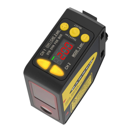
Display and Indicators
The display is a 4-digit, 7-segment LED. Run mode is the primary view displayed.
For 2-pt, BGS, FGS, and DYN TEACH modes, the display shows the current distance to the target in centimeters. For dual TEACH
mode, the display shows the percentage matched to the taught reference surface. A display value of
has not been taught.
Figure 1. Display in Run Mode
1
STB DYN FGS BGS
Output Indicator
•
On—Output is on
•
Off—Output is off
Stability Indicator (STB)
•
On—Stable signal within the specified sensing range
•
Flashing—Marginal signal, the target is outside the limits
of the specified sensing range, or a multiple peak
condition exists
•
Off—No target detected within the specified sensing
range
Original Document
208795 Rev. B
. Search for p/n 208794 to view the Instruction Manual. Use of this document assumes
3
2
1. Stability Indicator (STB—Green)
2. Active TEACH Indicators
•
DYN—Dynamic (Amber)
•
FGS—Foreground Suppression (Amber)
•
BGS—Background Suppression (Amber)
15 February 2019
1. Two output indicators (amber)
2. Display
3. Buttons
Active TEACH Indicators (DYN, FGS, and BGS)
•
DYN, FGS, and BGS all off—Two-point TEACH mode
selected (default)
•
DYN on—Dynamic TEACH mode selected
•
FGS on—Foreground suppression TEACH mode
selected
•
BGS on—Background suppression TEACH mode
selected
•
DYN, FGS, and BGS all on—Dual TEACH mode
selected
indicates the sensor
208795
Advertisement
Table of Contents

Related Manuals for Banner Q5X


Summary of Contents for Banner Q5X
- Page 1 Class 2 laser CMOS sensor with dual outputs and IO-Link. Patent pending. This guide is designed to help you set up and install the Q5X Laser Triangulation Sensor with Background Suppression. For complete information on programming, performance, troubleshooting, dimensions, and accessories, please refer to the Instruction Manual at www.bannerengineering.com...
-
Page 2: Laser Description And Safety Information
Q5X Laser Triangulation Sensor with Background Suppression Buttons Use the sensor buttons (SELECT)(TEACH), (+)(CH1/CH2), and (-)(MODE) to program the sensor. (SELECT)(TEACH) (+)(CH1/CH2) • Press to select menu items in Setup mode • Press to navigate the sensor menu in Setup mode •... -
Page 3: Mount The Device
See the following figures for examples of correct and incorrect sensor-to-target orientation as certain placements may pose problems for sensing some targets. The Q5X can be used in the less preferred orientation and at steep angles of incidence and still provide reliable detection performance due to its high excess gain. -
Page 4: Wiring Diagram
Q5X Laser Triangulation Sensor with Background Suppression Wiring Diagram Load 10-30V dc Load 10-30V dc – – Remote 1 = Brown Load Input 2 = White 3 = Blue Figure 9. Channel 2 as PNP Discrete or PFM Output Figure 10. Channel 2 as Remote Input 4 = Black Note: Open lead wires must be connected to a terminal block. - Page 5 Q5X Laser Triangulation Sensor with Background Suppression To exit Setup mode and return to Run mode, navigate to and press SELECT. Note: The number that follows a menu option, for example , indicates the channel that is selected. For menu items without a number (excluding submenu items), these menu options are only available from Channel 1 and the settings apply to both channels.
- Page 6 Q5X Laser Triangulation Sensor with Background Suppression Channel 2 Top Menu Sub Menu Output CH2 Light Operate default setting) Dark Operate Complimentary to Output 1 set: Remote Teach input laser off when pulled high laser on when pulled high master...
-
Page 7: Basic Teach Instructions
Q5X Laser Triangulation Sensor with Background Suppression Basic TEACH Instructions Use the following instructions to teach the Q5X sensor. The instructions provided on the sensor display vary depending on the type of TEACH mode selected. Two-point TEACH is the default TEACH mode. -
Page 8: Specifications
Q5X Laser Triangulation Sensor with Background Suppression When in mode, displays when (-)(MODE) is pressed and held. To access the manual adjust options, briefly press and release (+)(CH1/CH2) or (-)(MODE). To enter TEACH mode, press the (SELECT)(TEACH) button and hold for longer than 2 seconds. - Page 9 Q5X Laser Triangulation Sensor with Background Suppression Required Overcurrent Protection Shock MIL-STD-202G, Method 213B, Condition I (100G 6x along X, Y and Z axes, 18 shocks), with sensor operating WARNING: Electrical connections must be made by qualified personnel in accordance with...
-
Page 10: Performance Curves
Optimize reliable detection by applying these principals when selecting your reference surface, positioning your sensor relative to the reference surface, and presenting your target. The robust detection capabilities of the Q5X allows successful detection even under non-ideal conditions in many cases. Typical reference surfaces are metal machine frames, conveyor side rails, or mounted plastic targets. - Page 11 Banner Engineering Corp. Limited Warranty Banner Engineering Corp. warrants its products to be free from defects in material and workmanship for one year following the date of shipment. Banner Engineering Corp. will repair or replace, free of charge, any product of its manufacture which, at the time it is returned to the factory, is found to have been defective during the warranty period. This warranty does not cover damage or liability for misuse, abuse, or the improper application or installation of the Banner product.
Need help?
Do you have a question about the Q5X and is the answer not in the manual?
Questions and answers