Banner Q5X Instruction Manual
Dual discrete outputs and iolink
Hide thumbs
Also See for Q5X:
- Instruction manual (58 pages) ,
- Quick start manual (17 pages) ,
- Manual (15 pages)

Related Manuals for Banner Q5X


Summary of Contents for Banner Q5X
- Page 1 Q5X with Dual Discrete Outputs and IO- Link Instruction Manual Original Instructions p/n: 208794 Rev. J July 25, 2023 © Banner Engineering Corp. All rights reserved.
-
Page 2: Table Of Contents
Contents Contents ..........................2 Chapter 1 Product Description for the Q5X Dual Discrete Q5X Dual Discrete Models ................................... 5 Overview........................................5 Class 2 Laser Description and Safety Information..........................6 Features ........................................7 Display and Indicators ................................... 7 Buttons ........................................7 Chapter 2 Installation Sensor Orientation for the Triangulation Models ............................ - Page 3 Chapter 7 Accessories Cordsets ........................................55 Brackets........................................55 Reference Targets ..................................... 57 RSD1 Remote Display....................................57 Chapter 8 Product Support and Maintenance Troubleshooting ......................................59 Contact Us ........................................59 Banner Engineering Corp Limited Warranty............................... 59 Document Information ....................................60 ...
- Page 4 Blank page ...
-
Page 5: Chapter 1 Product Description For The Q5X Dual Discrete
Q5X With Dual Discrete Outputs And IO-Link Instruction Manual Chapter Contents Q5X Dual Discrete Models ....................................5 Overview ..........................................5 Features ..........................................7 Chapter 1 Product Description for the Q5X Dual Discrete • Laser measurement sensor with a range of up to 10 m •... -
Page 6: Class 2 Laser Description And Safety Information
Q5X With Dual Discrete Outputs And IO-Link Instruction Manual Class 2 Laser Description and Safety Information Read the following safety information for proper use of a Class 2 laser. CAUTION: • Return defective units to the manufacturer. • Use of controls or adjustments or performance of procedures other than those specified herein may result in hazardous radiation exposure. • Do not attempt to disassemble this sensor for repair. A defective unit must be returned to the man ufacturer. CAUTION: •... -
Page 7: Features
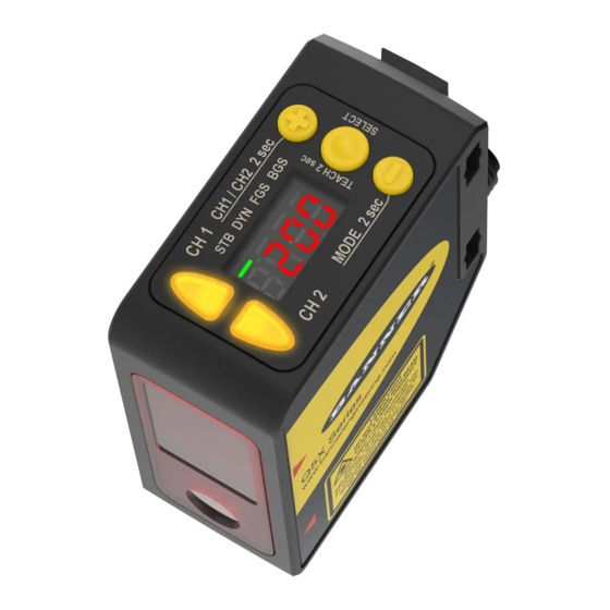
Q5X With Dual Discrete Outputs And IO-Link Instruction Manual Features The Q5X Laser Measurement Sensor has three major features. Q5X Features Two output indicators (amber) Display Buttons Display and Indicators The display is a 4digit, 7segment LED. Run mode is the primary view displayed. For 2-pt, BGS, FGS, and DYN TEACH modes, the display shows the current distance to the target in centimeters. For Dual TEACH mode, the display shows the percentage matched to the taught reference surface. A display value of 999P indicates ... - Page 8 Q5X With Dual Discrete Outputs And IO-Link Instruction Manual Press and hold for longer than 2 seconds to start the currently (-)(MODE) selected TEACH mode (the default is two-point TEACH) Press to navigate the sensor menu in Setup mode (+)(CH1/CH2) Press to change setting values;...
-
Page 9: Chapter 2 Installation
Q5X With Dual Discrete Outputs And IO-Link Instruction Manual Chapter Contents Sensor Orientation for the Triangulation Models ..............................9 Mount the Device ......................................10 Wiring Diagram........................................10 Cleaning and Maintenance ....................................11 Connecting to RSD1 ......................................11 Button Map from RSD1 to Sensor..................................13 ... -
Page 10: Mount The Device
Q5X With Dual Discrete Outputs And IO-Link Instruction Manual Continued from page 9 Orientation for a color or luster difference Orientation for highly reflective target (Optimal) Reflective Horizontal Surface (optional) Orientation Orientation Mount the Device If a bracket is needed, mount the device onto the bracket. Mount the device (or the device and the bracket) to the machine or equipment at the desired location. Do not tighten the mounting screws at this time. ... -
Page 11: Cleaning And Maintenance
MQDEC3-503SS MQDEC3-506SS MQDEC3-515SS MQDEC3-530SS Flying Lead Shielded Double Ended Sensor Pin 2 to Pin 5 MQDEC2-506 MQDC-4501SS MQDEC2-515 MQDC-4506SS RSD1 MQDEC2-530 Use these cordsets to connect the RSD1 to the Q5X sensor. July 25, 2023 © Banner Engineering Corp. - Page 12 Q5X With Dual Discrete Outputs And IO-Link Instruction Manual 4Pin Female and 5Pin Male Threaded M12 Cordset—Double Ended Model Length "L1" Style Pinout MQDC-4501SS 0.30 m (0.98 ft) Male 1 = Brown 2 = Not Used Female Straight/ Male Straight 3 = Blue MQDC-4506SS 1.83 m (6.00 ft) 4 = Black 5 = White M12 X 1.0 M12 X 1.0 Female 1 = Brown ø 14.5 ø 14.5 2 = White ...
-
Page 13: Button Map From Rsd1 To Sensor
Q5X With Dual Discrete Outputs And IO-Link Instruction Manual Continued from page 12 5Pin Threaded M12 Cordsets with Shield—Single Ended Model Length Style Dimensions Pinout (Female) 32 Typ. MQDEC2-506RA 2 m (6.56 ft) [1.26"] MQDEC2-515RA 5 m (16.4 ft) MQDEC2-530RA 9 m (29.5 ft) 30 Typ. [1.18"] RightAngle MQDEC2-550RA 15 m (49.2 ft) MQDEC2-575RA 23 m (75.44 ft) M12 x 1 ø... - Page 14 Blank page ...
-
Page 15: Chapter 3 Sensor Programming
Q5X With Dual Discrete Outputs And IO-Link Instruction Manual Chapter Contents Channel 1 and Channel 2 (CH1/CH2) ................................15 Setup Mode ........................................15 Manual Adjustments ......................................26 Remote Input........................................26 Locking and Unlocking the Sensor Buttons............................... 28 Button Instructions......................................28 Remote Input Instructions ....................................28 TEACH Procedures ......................................29 Pulse Frequency Modulation (PFM) Output (PULS) ............................ - Page 16 Q5X With Dual Discrete Outputs And IO-Link Instruction Manual Sensor Menu Map—Channel 1 July 25, 2023 © Banner Engineering Corp.
- Page 17 Q5X With Dual Discrete Outputs And IO-Link Instruction Manual Sensor Menu Map—Channel 2 July 25, 2023 © Banner Engineering Corp.
-
Page 18: Output (Out1 And Out2)
Q5X With Dual Discrete Outputs And IO-Link Instruction Manual Output (out1 and out2) The Output 1 and Output 2 menus differ between Channel 1 and Channel 2. NOTE: The number that follows out on the display indicates which channel is selected. The Output 1 menu is available in Channel 1. Use this menu to select light operate (LO) or dark operate (DO). The default output configuration is light operate. -
Page 19: Window Size (Wnd1 And Wnd2)
Q5X With Dual Discrete Outputs And IO-Link Instruction Manual NOTE: The number that follows trc on the display indicates which channel is selected. • —HighSpeed Adaptive Tracking On • —Adaptive Tracking On (default) • —Adaptive Tracking Off OFF disables the Adaptive Tracking Algorithm—Prevents the sensor from adjusting the thresholds around the taught refer ence surface while the sensor is in dual mode. The sensor will not adapt to or learn any target. Environmental changes may cause the displayed value to deviate from 100P (100%) over time. A periodic reteach of the reference surface may be re... -
Page 20: Gain And Sensitivity (Gain)
Q5X With Dual Discrete Outputs And IO-Link Instruction Manual 2000 mm Models Response Speed Response Speed in Sync Mode Repeatability Ambient Light Rejection Excess Gain 3 ms 6 ms 1000 µs Disabled 5 ms 10 ms 1600 µs Enabled See Excess Gain in "Q5X Dual Dis 15 ms 30 ms 3 ms Enabled crete with IO-Link Specifications" on page 39 25 ms 50 ms ... - Page 21 Q5X With Dual Discrete Outputs And IO-Link Instruction Manual Output Timing Delays Output OFF Delay ON Delay 1-Shot Time (D = 1ms - 90.0s) When one of the timing delay options is chosen, the sensor returns to the Setup menu and additional options become avail able to set the parameter(s): • —On delay • —Off delay • —Oneshot delay timer NOTE: For the one-shot delay timer: •...
-
Page 22: Hysteresis (Hys1 And Hys2)
Q5X With Dual Discrete Outputs And IO-Link Instruction Manual • 1 to 999 ms (when dt1 or dt2 is selected, the 1 to 9 ms range is available for 1.5, 2, 3, and 5 ms response times) • 1.0 to 90.0 s From Run mode, press SELECT to change the display to show the current totalizer count. Pressing SELECT again changes the display back to the measured distance. The totalizer count automatically resets after reteaching the switch point distance or turning the sensor off. Hysteresis (hYS1 and hYS2) Use this menu to set the hysteresis distance around the switch point. • —The sensor automatically selects a recommended minimum hysteresis distance relative to the current switch point distance, • to —Enter a userselectable value (cm) of hysteresis distance relative to the current switch point distance. Set Distance—The distance from the reference surface that allows stable use, including the effects of temperature and volt age, to the (standard) sensing object transit position. This is approximately 70% to 80% of the normal (rated) sensing dis tance. Set Distance Set Distance Hysteresis (Differential Travel)—With respect to the distance between the standard sensing object and the sensor, the differ ence between the distance at which the sensor operates and the distance at which the sensor resets. ... -
Page 23: Zero Reference Location (Zero)
Q5X With Dual Discrete Outputs And IO-Link Instruction Manual NOTE: Smaller hysteresis values cause the output to switch state with less differential travel. A larger hysteresis value makes the output state to remain unchanged with larger differential travel. Negative hys teresis values allow the operator to move the hysteresis to either side of the switch point. Zero Reference Location (ZEro) Use this menu to select the zeroreference location. Changing the zeroreference location only affects the readout on the dis play and does not affect the output. The default is nEAr, 0 = the front of the sensor. This menu is not available in dual (intensity + distance) mode. —0 is the front of the sensor and the measurement increases further from the sensor. —0 is the maximum range and the measurement increases closer to the sensor. Shift the Zero Reference Location after a TEACH (ShFt) Use this menu to select whether the sensor shifts the zeroreference location based on the last TEACH process. ... -
Page 24: Offset (Ofs1 And Ofs2)
Q5X With Dual Discrete Outputs And IO-Link Instruction Manual Example Zero and Shift settings Display Reference Display Reference Zero = Near Shift = Off 50 cm (Default Setting) Zero = Far Shift = Off 50 cm Display Reference Display Reference... -
Page 25: Display View (Disp)
—Solid state PNP on pins 2 and 4 • —Solid state NPN on pins 2 and 4 Exit Setup Mode (End) Use this menu to end Setup mode. Navigate to End and press SELECT to exit Setup mode and return to Run mode. Reset to Factory Defaults Use this menu to restore the sensor to the factory default settings. —Select to return to the sensor menu without restoring the defaults. —Select to apply the factory defaults and return to Run mode. Factory Default Settings for the Q5X Dual Discrete with IO-Link The 2000 mm model and the 5000 mm model have different factory default settings. Factory Default Settings Setting 2000 mm Model Factory Default 5000 mm Model Factory Default Delay Timers ( ) —No delay —No delay Display View ( ) ... -
Page 26: Manual Adjustments
Q5X With Dual Discrete Outputs And IO-Link Instruction Manual Continued from page 25 Setting 2000 mm Model Factory Default 5000 mm Model Factory Default Hysteresis ( ) —Sensor controls value —Sensor controls value Display Units ( ) —Centimeters —Centimeters —Default: IOLink on pin 4 and PNP —Default: IOLink on pin 4 and Output Polarity ( ) on pin 2 PNP on pin 2 Manual Adjustments Manually adjust the sensor switch point using the + and - buttons. From Run mode, press either + or - one time. The selected channel displays briefly, then the current switch point val ue flashes slowly. ... -
Page 27: Select The Teach Mode Using The Remote Input
Q5X With Dual Discrete Outputs And IO-Link Instruction Manual Remote Input Map Remote Input Wire Function = Set Input wiring diagram Dynamic background suppression One-point window (foreground suppression) One-point background suppression Dual, intensity + distance Button Lock Button Unlock (uloc) Button Lock (loc) -
Page 28: Reset To Factory Defaults Using The Remote Input
Q5X With Dual Discrete Outputs And IO-Link Instruction Manual Continued from page 27 Action Result Pulses TEACH Mode 5 Dual (intensity + distance) Reset to Factory Defaults Using the Remote Input Follow the instructions below to reset the Q5X to factory defaults using Remote Input. Eightpulse the remote input to apply the factory defaults and return to Run mode. The input wire function remains at remote teach input (SEt). Locking and Unlocking the Sensor Buttons Use the lock and unlock feature to prevent unauthorized or accidental programming changes. ... -
Page 29: Teach Procedures
Q5X With Dual Discrete Outputs And IO-Link Instruction Manual Continued from page 28 Action Result Loc displays and the sensor returns to Run Doublepulse the remote input to lock the sensor. mode. Triple-pulse the remote input to apply the operator... -
Page 30: Dynamic Background Suppression (Dyn)
Q5X With Dual Discrete Outputs And IO-Link Instruction Manual Continued from page 29 Method Action Result Remote Input No action required. N/A Teach the sensor. Method Action Result Push Button Press TEACH to teach the target. The sensor is taught the first tar get. SEt, 2nd, and the current distance measurement flash alternately on the dis Remote Input ... - Page 31 Q5X With Dual Discrete Outputs And IO-Link Instruction Manual Dynamic Background Suppression NOTE: The sensor must be set to tch = dYn to use the following instructions. The DYN indicator is amber to indicator Dynamic TEACH mode. NOTE: To program the sensor using remote input, remote input must be enabled (out2 = SEt). Present the target.
-
Page 32: One-Point Window (Foreground Suppression) (Fgs)
Q5X With Dual Discrete Outputs And IO-Link Instruction Manual Method Action Result Push Button Press TEACH to stop teaching the sensor. The new switch point flashes rapidly and the sensor returns to Run mode. Remote Input Singlepulse the remote input. See "Q5X Dual Discrete with IO-Link Performance Curves" on page 43 for the minimum object separation. Expected TEACH Behavior for Dynamic Background Suppression Condition ... -
Page 33: One-Point Background Suppression (Bgs)
Q5X With Dual Discrete Outputs And IO-Link Instruction Manual Method Action Result Push Button Present the target. The sensor-to-target distance must be within the sensor's The target's measurement value displays. range. Remote Input Start the TEACH mode. Method Action Result Light Operate SEt and on flash alternately on the dis... - Page 34 Q5X With Dual Discrete Outputs And IO-Link Instruction Manual One-Point Background Suppression Switch Point NOTE: The sensor must be set to tch = bGS to use the following instructions. The BGS indicator is amber to indicate Background Suppression mode. NOTE: To program the sensor using remote input, remote input must be enabled (out2 = SEt). Present the target. Method Action Result Push Button ...
-
Page 35: Dual (Intensity + Distance) (Dual)
Q5X With Dual Discrete Outputs And IO-Link Instruction Manual Expected TEACH Behavior for One-Point Background Suppression Condition TEACH Result Display One valid TEACH point Sets a switch point in front of the taught distance equal to The switch point distance flashes on the dis If an Offset is applied, the TEACH point is the nonuniform reflectivity minimum object separation. ... -
Page 36: Pulse Frequency Modulation (Pfm) Output (Puls)
Q5X With Dual Discrete Outputs And IO-Link Instruction Manual Method Action Result Push Button Press the TEACH button. The switching threshold flashes rapidly and the sensor returns to Run mode. Remote Input Singlepulse the remote input. Expected TEACH Behavior for Dual (Intensity + Distance) Mode Condition TEACH Result Display Sets a dual (intensity + distance) window cen... -
Page 37: Chapter 4 Io-Link Interface
Parameter Data AOIs—These files require the use of an associated IOLink Master AOI. The job of a Parameter Data AOI, when working in conjunction with the IOLink Master AOI, is to provide quasirealtime read/write access to all IOLink para meter data in the sensor. Each Parameter Data AOI is specific to a given sensor or device. IO-Link Master AOIs—These files require the use of one or more associated Parameter Data AOIs. The job of an IOLink Master AOI is to translate the desired IOLink read/write requests, made by the Parameter Data AOI, into the format a specif ic IOLink Master requires. Each IOLink Master AOI is customized for a given brand of IOLink Master. Add and configure the relevant Banner IO-Link Master AOI in your ladder logic program first; then add and configure Banner IOLink Device AOIs as desired, linking them to the Master AOI as shown in the relevant AOI documentation. July 25, 2023 © Banner Engineering Corp. - Page 38 Blank page ...
-
Page 39: Chapter 5 Specifications
Q5X With Dual Discrete Outputs And IO-Link Instruction Manual Chapter Contents FCC Part 15 Class A ......................................42 Industry Canada ICES-003(A)................................... 42 Dimensions........................................42 Q5X Dual Discrete with IO-Link Performance Curves ............................43 Chapter 5 Specifications Power and Beam Specifications... - Page 40 Q5X With Dual Discrete Outputs And IO-Link Instruction Manual Temperature Effect (Typical) for 5000 and 10000 mm Models Typical Excess Gain for the 2000 mm Model < 0.5mm/°C for up to 3000 mm < 0.75mm/°C for up to 5000 mm High Excess Gain (Standard Excess Gain) Using a 90% White Card <...
- Page 41 Q5X With Dual Discrete Outputs And IO-Link Instruction Manual Typical Excess Gain for the 10000 mm Model Beam Spot Size Typical Excess Gain Using a 90% White Card at 50 at 600 at 1000 at 2000 at 5000 at 6000...
-
Page 42: Fcc Part 15 Class A
Q5X With Dual Discrete Outputs And IO-Link Instruction Manual FCC Part 15 Class A This equipment has been tested and found to comply with the limits for a Class A digital device, pursuant to part 15 of the FCC Rules. These limits are designed to provide reasonable protection against harmful interference when the equipment is operated in a commercial environment. -
Page 43: Q5X Dual Discrete With Io-Link Performance Curves
Q5X With Dual Discrete Outputs And IO-Link Instruction Manual Q5X Dual Discrete with IO-Link Performance Curves Minimum object separation distance (90% to 6% reflectance) for the 2000 mm models Background Switch Point Distance Typical performance curves for the 2000 mm models... - Page 44 Q5X With Dual Discrete Outputs And IO-Link Instruction Manual Typical performance curves for the 3000 mm models Matte targets with a non-uniform reflectivity: 6% to 90% Matte targets with uniform reflectivity: 6% to 90% 1000 1500 2000 2500 3000...
- Page 45 Q5X With Dual Discrete Outputs And IO-Link Instruction Manual Continued from page 44 Minimum Object Separation for 50 ms Response Time Repeatability for 50 ms Response Time Minimum Object Separation Repeatability (50 ms) 6% black/90% white 6% black 18% Gray...
- Page 46 Q5X With Dual Discrete Outputs And IO-Link Instruction Manual Typical performance curves for the 10000 mm models Minimum Object Separation for 250 ms Response Time Repeatability for 250 ms Response Time Minimum Object Separation (250 ms) Repeatability (250 ms)
- Page 47 Q5X With Dual Discrete Outputs And IO-Link Instruction Manual Continued from page 46 Minimum Object Separation for 5 ms Response Time Repeatability for 5 ms Response Time Minimum Object Separation (5 ms) Repeatability (5ms) 6% Black 6% black/90% white...
- Page 48 Blank page ...
-
Page 49: Chapter 6 Additional Information
Q5X With Dual Discrete Outputs And IO-Link Instruction Manual Chapter Contents Dual (Intensity + Distance) Mode ..................................49 Dual Mode Reference Surface Considerations ..............................49 Dual Mode Considerations for Clear and Transparent Object Detection ......................50 Abbreviations ........................................51 ... -
Page 50: Dual Mode Considerations For Clear And Transparent Object Detection
Q5X With Dual Discrete Outputs And IO-Link Instruction Manual ◦ Matte or diffuse surface finish ◦ Fixed surface with no vibration ◦ Dry surface with no buildup of oil, water, or dust Position the reference surface between 200 mm (20 cm) and the maximum sensing range. Position the target to be detected as close to the sensor as possible, and as far away from the reference surface as possible. Angle the sensing beam relative to the target and relative to the reference surface 10 degrees or more. Dual Mode Considerations for Clear and Transparent Object Detection The Q5X is able to detect the very small changes caused by transparent and clear objects. A transparent object can be de tected either by a change in intensity, distance, or by a doublepeak reflection. The Q5X sensor can be taught nonideal reference surfaces, such as surfaces outside of the sensor range or very dark sur faces. Teaching non-ideal reference surfaces may enable applications other than transparent or clear object detection, but best results for transparent or clear object detection require a stable reference surface. ... -
Page 51: Abbreviations
Q5X With Dual Discrete Outputs And IO-Link Instruction Manual Common problems and solutions for detecting clear objects—Object too close PROBLEM: SOLUTION: The object is close to the reference surface Move the target closer to the sensor Common problems and solutions for detecting clear objects—Sensor too far PROBLEM: SOLUTION: The sensor is far from the object Move the sensor closer to the target Abbreviations ... - Page 52 Q5X With Dual Discrete Outputs And IO-Link Instruction Manual Continued from page 51 Abbreviation Description Cancel Complementary output Display read Delay , Output timing delay (Channel 1, Channel 2) Dark operate Delay timer (Channel 1, Channel 2) , Dual mode Dynamic background suppression End—exit the sensor menu Far zero reference location—the maximum range is 0 and the measurement in crease as the target moves closer to the sensor ...
- Page 53 Q5X With Dual Discrete Outputs And IO-Link Instruction Manual Continued from page 52 Abbreviation Description Laser off Master Near zero reference location—the front of the sensor is 0 and the measurement in crease as the target moves further away from the sensor Object Off delay timer (Channel 1, Channel 2) , Off Offset (Channel 1, Channel 2) , An applied offset resulted in an invalid switch point On On delay timer (Channel 1, Channel 2) , ...
- Page 54 Q5X With Dual Discrete Outputs And IO-Link Instruction Manual Continued from page 53 Abbreviation Description TEACH process selection (Channel 1, Channel 2) , Totalizer Total counts , Unlock/unlocked Unit Saturated signal (too much light) Window size (Channel 1, Channel 2) , Yes Zero—select the zero reference location July 25, 2023...
-
Page 55: Cordsets
Q5X With Dual Discrete Outputs And IO-Link Instruction Manual Chapter Contents Cordsets ..........................................55 Brackets ..........................................55 Reference Targets ......................................57 RSD1 Remote Display ...................................... 57 Chapter 7 Accessories Cordsets 4Pin Threaded M12 Cordsets—Single Ended Model Length Style Dimensions Pinout (Female) MQDC-406 2 m (6.56 ft) 44 Typ. - Page 56 Q5X With Dual Discrete Outputs And IO-Link Instruction Manual Continued from page 55 B = 7 × M3 × 0.5 Bolt thread (A): 3/8 16 × 2¼ in for SMBQ5XFA: M10 1.5 × 50 for SMBQ5XFAM10; n/a; no bolt included. Mounts directly to 12 mm (½ in) rods for SMBQ5XFAM12 R3.4 Ø6.7 SMBAMSQ5XIPRA • Enclosed bracket • 13ga. Stainless steel with borosilicate glass window • Right angle mount plate Ø6.7 SMBAMSQ5XIPP R3.4 • Enclosed bracket • 13ga stainless steel with a borosilicate glass window • Flat mount plate SMBQ5XDT •...
-
Page 57: Reference Targets
Q5X With Dual Discrete Outputs And IO-Link Instruction Manual SMBQ5XM4F • Fixing plates for mounting to back of sensor • Stainless steel plates • Customer supplied mounting plate thickness minimum 2 mm maxi mum 4 mm with screws included in kit Reference Targets All measurements are listed in millimeters, unless noted otherwise. BRTQ4X60X18 • Reference target for clear object detection or dualmode applications • FDA grade acetal material BRTQ4X60X50 • Reference target for clear object detection or dualmode applications •... - Page 58 Blank page ...
-
Page 59: Troubleshooting
Banner Engineering Corp. warrants its products to be free from defects in material and workmanship for one year following the date of shipment. Banner Engineering Corp. will repair or replace, free of charge, any product of its manufacture which, at the time it is returned to the factory, is found to have been defective during the warranty period. -
Page 60: Document Information
WHETHER ARISING IN CONTRACT OR WARRANTY, STATUTE, TORT, STRICT LIABILITY, NEGLIGENCE, OR OTHER WISE. Banner Engineering Corp. reserves the right to change, modify or improve the design of the product without assuming any obligations or liabilities relating to any product previously manufactured by Banner Engineering Corp. Any misuse, abuse, or improper application or installation of this product or use of the product for personal protection applications when the product is identified as not intended for such purposes will void the product warranty. - Page 61 LinkedIn Twitter Facebook © 2023. All rights reserved. www.bannerengineering.com...
Need help?
Do you have a question about the Q5X and is the answer not in the manual?
Questions and answers