Banner Q5X Quick Start Manual
Laser triangulation sensor with dual mode for jam detection
Hide thumbs
Also See for Q5X:
- Instruction manual (61 pages) ,
- Quick start manual (17 pages) ,
- Manual (15 pages)
Table of Contents
Advertisement
Quick Links
Q5X Laser Triangulation Sensor with Dual Mode
for Jam Detection
Quick Start Guide
Class 2 laser CMOS sensor with dual outputs. Patent pending.
This guide is designed to help you set up and install the Q5X Laser Triangulation Sensor with Dual Mode for Jam Detection. For
complete information on programming, performance, troubleshooting, dimensions, and accessories, please refer to the Instruction
Manual at www.bannerengineering.com. Search for p/n 218902 to view the Instruction Manual. Use of this document assumes
familiarity with pertinent industry standards and practices.
WARNING:
•
Do not use this device for personnel protection
•
Using this device for personnel protection could result in serious injury or death.
•
This device does not include the self-checking redundant circuitry necessary to allow its use in
personnel safety applications. A device failure or malfunction can cause either an energized (on) or de-
energized (off) output condition.
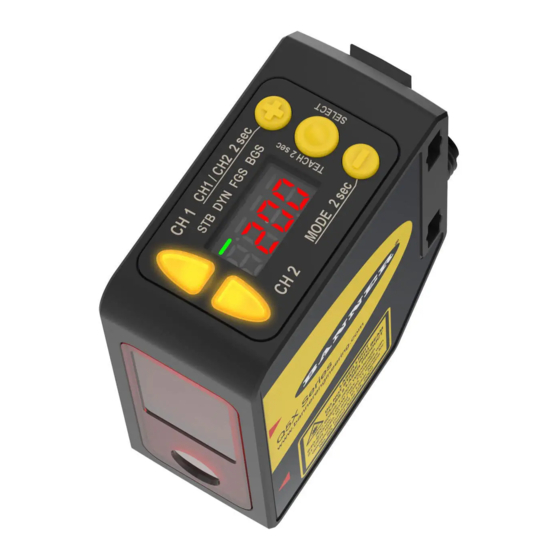
Features
The Q5X has three major features.
Figure 1. Q5X Features
2
1
Display and Indicators
The display is a 4-digit, 7-segment LED. Run mode is the primary view displayed.
For JRET, JBGS, 2-pt, BGS, FGS, and DYN TEACH modes, the display shows the current distance to the target in centimeters. For
Dual TEACH mode, the display shows the percentage matched to the taught reference surface. A display value of
the sensor has not been taught.
Figure 2. Display in Run Mode
1
STB FLO RET BGS
Original Document
218598 Rev. C
3
2
1. Stability Indicator (STB—Green)
2. Active TEACH Indicators
•
FLO—Amber
•
RET—Amber
•
BGS—Amber
4 August 2021
1. Two output indicators (amber)
2. Display
3. Buttons
indicates
218598
Advertisement
Table of Contents

Related Manuals for Banner Q5X


Summary of Contents for Banner Q5X
- Page 1 Class 2 laser CMOS sensor with dual outputs. Patent pending. This guide is designed to help you set up and install the Q5X Laser Triangulation Sensor with Dual Mode for Jam Detection. For complete information on programming, performance, troubleshooting, dimensions, and accessories, please refer to the Instruction Manual at www.bannerengineering.com.
- Page 2 Q5X Laser Triangulation Sensor with Dual Mode for Jam Detection Output Indicator Active TEACH Indicators (FLO, RET, BGS) • On—Output is on • RET on—Jam Retroreflective TEACH mode selected (default) • Off—Output is off • BGS on—Jam Background Suppression TEACH mode...
- Page 3 See the following figures for examples of correct and incorrect sensor-to-target orientation as certain placements may pose problems for sensing some targets. The Q5X can be used in the less preferred orientation and at steep angles of incidence and still provide reliable detection performance due to its high excess gain.
-
Page 4: Mount The Device
Q5X Laser Triangulation Sensor with Dual Mode for Jam Detection Figure 9. Orientation for a color or luster difference Figure 10. Orientation for highly reflective target Reflective (Optimal) Horizontal Vertical Surface Orientation Orientation (optional) Mount the Device 1. If a bracket is needed, mount the device onto the bracket. -
Page 5: Cleaning And Maintenance
Blow the window clear using filtered, compressed air, then clean as necessary using only water and a lint-free cloth. Connecting to RSD1 The following diagram depicts the connection of the Q5X to the optional RSD1 accessory. Figure 17. Q5X to RSD1 Double Ended Shielded... - Page 6 Q5X Laser Triangulation Sensor with Dual Mode for Jam Detection 4-Pin Female and 5-Pin Male Threaded M12 Cordset—Double Ended Model Length "L1" Style Pinout M12 X 1.0 M12 X 1.0 Female 1 = Brown ø 14.5 ø 14.5 2 = White...
-
Page 7: Sensor Programming
Q5X Laser Triangulation Sensor with Dual Mode for Jam Detection Button Map from RSD1 to Sensor The sensor may be optionally connected to the Banner RSD1 remote display accessory. Refer to this table for the RSD1 button association with your sensor. - Page 8 Q5X Laser Triangulation Sensor with Dual Mode for Jam Detection Figure 18. Sensor Menu Map—Channel 1 Channel 1 Top Menu Sub Menu default setting) Output CH1 Select Zero Reference Location CH1 & CH2 Light Operate near: set zero displayed value to the housing face...
- Page 9 Q5X Laser Triangulation Sensor with Dual Mode for Jam Detection Figure 19. Sensor Menu Map—Channel 2 Channel 2 Top Menu Sub Menu Output CH2 Light Operate default setting) Dark Operate Complimentary to Output 1 set: Remote Teach input laser off when pulled high...
-
Page 10: Basic Teach Instructions
Basic TEACH Instructions Use the following instructions to teach the Q5X sensor. The instructions provided on the sensor display vary depending on the type of TEACH mode selected. Jam Retroreflective TEACH is the default TEACH mode on CH1, and Jam Background Suppression TEACH is the default TEACH mode on CH2. -
Page 11: Specifications
Q5X Laser Triangulation Sensor with Dual Mode for Jam Detection • —The sensor is unlocked and all settings can be modified (default). • — The sensor is locked and no changes can be made. • —The switch point value can be changed by teaching or manual adjustment, but no sensor settings can be changed through the menu. - Page 12 Q5X Laser Triangulation Sensor with Dual Mode for Jam Detection Beam Spot Size Remote Input Allowable Input Voltage Range: 0 to Vsupply Active High (internal weak pull-down): High state > (Vsupply – 2.25 V) at 2 mA maximum Active Low (internal weak pull-up): Low state < 2.25 V at 2 mA maximum...
-
Page 13: Performance Curves
The robust detection capabilities of the Q5X allows successful detection even under non-ideal conditions in many cases. Typical reference surfaces are metal machine frames, conveyor side rails, or mounted plastic targets. Contact Banner Engineering if you require assistance setting up a stable reference surface in your application. - Page 14 Banner Engineering Corp. Limited Warranty Banner Engineering Corp. warrants its products to be free from defects in material and workmanship for one year following the date of shipment. Banner Engineering Corp. will repair or replace, free of charge, any product of its manufacture which, at the time it is returned to the factory, is found to have been defective during the warranty period. This warranty does not cover damage or liability for misuse, abuse, or the improper application or installation of the Banner product.
Need help?
Do you have a question about the Q5X and is the answer not in the manual?
Questions and answers