Banner Q5X Quick Start Manual
Hide thumbs
Also See for Q5X:
- Instruction manual (61 pages) ,
- Quick start manual (15 pages) ,
- Manual (15 pages)
Table of Contents
Advertisement
Quick Links
Q5X with Dual Discrete Outputs and IO-
Link Quick Start Guide
Product Description for the Q5X Dual Discrete
This guide is designed to help you set up and install the Q5X Laser Measurement Sensor. For complete information on programming, perfor
mance, troubleshooting, dimensions, and accessories, please refer to the Instruction Manual at www.bannerengineering.com. Search for p/
n 208794 to view the Instruction Manual. Use of this document assumes familiarity with pertinent industry standards and practices.
WARNING:
•
Do not use this device for personnel protection
•
Using this device for personnel protection could result in serious injury or death.
•
This device does not include the selfchecking redundant circuitry necessary to allow its use in personnel safe
ty applications. A device failure or malfunction can cause either an energized (on) or de-energized (off) output
condition.
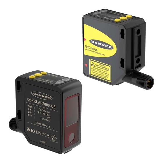
Features
The Q5X Laser Measurement Sensor has three major features.
Q5X Features
2
1
Display and Indicators
The display is a 4digit, 7segment LED. Run mode is the primary view displayed.
For 2-pt, BGS, FGS, and DYN TEACH modes, the display shows the current distance to the target in centimeters. For Dual TEACH mode,
the display shows the percentage matched to the taught reference surface. A display value of 999P indicates the sensor has not been
taught.
Display in Run Mode
1
STB DYN FGS BGS
Output Indicator
On: The output is on
Off: The output is off
Stability Indicator (STB)
On—Stable signal within the specified sensing range
Flashing—Marginal signal (low excess gain), the target is out
side the limits of the specified sensing range, or a multiple
peak condition exists
Off—No target is detected within the specified sensing range
Original Instructions
July 25, 2023
3
1.
Two output indicators (amber)
2.
Display
3.
Buttons
2
1.
Stability Indicator (STB—Green)
2.
Active TEACH Indicators
◦
DYN—Dynamic (Amber)
◦
FGS—Foreground Suppression (Amber)
◦
BGS—Background Suppression (Amber)
© Banner Engineering Corp.
Active TEACH Indicators (DYN, FGS, and BGS)
DYN, FGS, and BGS all off—Twopoint TEACH mode select
ed (default)
DYN on—Dynamic TEACH mode selected
FGS on—Foreground suppression TEACH mode selected
BGS on—Background suppression TEACH mode selected
DYN, FGS, and BGS all on—Dual TEACH mode selected
p/n: 208795 Rev. H
208795
Advertisement
Table of Contents

Related Manuals for Banner Q5X


Summary of Contents for Banner Q5X
- Page 1 Q5X with Dual Discrete Outputs and IO- Link Quick Start Guide Product Description for the Q5X Dual Discrete This guide is designed to help you set up and install the Q5X Laser Measurement Sensor. For complete information on programming, perfor mance, troubleshooting, dimensions, and accessories, please refer to the Instruction Manual at www.bannerengineering.com. Search for p/ n 208794 to view the Instruction Manual. Use of this document assumes familiarity with pertinent industry standards and practices. WARNING: • Do not use this device for personnel protection • Using this device for personnel protection could result in serious injury or death.
- Page 2 Q5X with Dual Discrete Outputs and IO-Link Quick Start Guide Buttons Use the sensor buttons (SELECT)(TEACH), (+)(CH1/CH2), and (-)(MODE) to program the sensor. Button Layout (SELECT/TEACH) (-)(MODE) Press to select menu items in Setup mode Press to navigate the sensor menu in Setup mode Press and hold for longer than 2 seconds to start the currently Press to change setting values;...
- Page 3 Q5X with Dual Discrete Outputs and IO-Link Quick Start Guide Class 2 Red Laser models with maximum range of 2000 mm: Reference IEC 608251:2007 Output: < 1.0 mW FDA (CDRH) warning label (Class Laser wavelength: 640 to 670 nm LASER LIGHT DO NOT STARE INTO BEAM CLASS 2 LASER PRODUCT IEC 60825-1:2007. Wavelength 640-670nm; 1.0mW max. Complies with Pulse Duration: 20 µs to 2 ms ...
-
Page 4: Mount The Device
Q5X with Dual Discrete Outputs and IO-Link Quick Start Guide Orientation for a moving ob Orientation for a height dif Orientation by a wall ject ference Orientation for a color or Orientation for highly reflec luster difference tive target (Optimal) Reflective Horizontal Surface (optional) Orientation Orientation Mount the Device If a bracket is needed, mount the device onto the bracket. Mount the device (or the device and the bracket) to the machine or equipment at the desired location. Do not tighten the mounting screws at this time. ... -
Page 5: Cleaning And Maintenance
MQDEC3-515SS MQDEC3-530SS Flying Lead Shielded Double Ended Sensor Pin 2 to Pin 5 MQDEC2-506 MQDC-4501SS MQDC-4506SS MQDEC2-515 RSD1 MQDEC2-530 Use these cordsets to connect the RSD1 to the Q5X sensor. 4Pin Female and 5Pin Male Threaded M12 Cordset—Double Ended Model Length "L1" Style Pinout MQDC-4501SS 0.30 m (0.98 ft) Male 1 = Brown 2 = Not Used ... - Page 6 MQDEC2-5100RA 31 m (101.68 ft) Button Map from RSD1 to Sensor The sensor may be optionally connected to the Banner RSD1 remote display accessory. Refer to this table for the RSD1 button association with your sensor. page 6 July 25, 2023 © Banner Engineering Corp.
-
Page 7: Sensor Programming
Q5X with Dual Discrete Outputs and IO-Link Quick Start Guide Button association between the RSD1 and the Q4X/Q5X sensors Device Up Button Down Button Enter Button Escape Button RSD1 Q4X and Q5X N/A Sensor Programming Program the sensor using the buttons on the sensor or the remote input (limited programming options). In addition to programming the sensor, use the remote input to disable the buttons for security, preventing unauthorized or accidental pro gramming changes. See the Instruction Manual, p/n 208794 for more information. Setup Mode Access Setup mode and the sensor menu from Run mode by pressing and holding MODE for longer than 2 seconds. ... - Page 8 Q5X with Dual Discrete Outputs and IO-Link Quick Start Guide Sensor Menu Map—Channel 1 page 8 July 25, 2023 © Banner Engineering Corp.
- Page 9 Q5X with Dual Discrete Outputs and IO-Link Quick Start Guide Sensor Menu Map—Channel 2 July 25, 2023 page 9 © Banner Engineering Corp.
-
Page 10: Manual Adjustments
Q5X with Dual Discrete Outputs and IO-Link Quick Start Guide Basic TEACH Instructions Use the following instructions to teach the Q5X sensor. The instructions provided on the sensor display vary depending on the type of TEACH mode selected. Two-point TEACH is the default TEACH mode. Press and hold TEACH for longer than 2 seconds to start the selected TEACH mode. Present the target. Press TEACH to teach the target. The target is taught and the sensor waits for the second target, if required by the selected TEACH mode, or returns to Run mode. Complete these steps only if it is required for the selected TEACH mode. Present the second target. Press TEACH to teach the target. The target is taught and the sensor returns to Run mode. See the Instruction Manual for detailed instructions and other available TEACH modes. The TEACH modes include: •... - Page 11 Q5X with Dual Discrete Outputs and IO-Link Quick Start Guide Q5X Dual Discrete with IO-Link Specifications Power and Beam Specifications Supply Voltage (Vcc) Sensing Range 10 to 30 V DC (Class 2 supply) (10% max ripple within limits) 2000 mm model: 95 mm to 2000 mm (3.74 in to 78.74 in) 3000 mm model: 95 mm to 3000 mm (3.74 in to 118.11 in) Supply Protection Circuitry ...
- Page 12 Q5X with Dual Discrete Outputs and IO-Link Quick Start Guide Output Rating Typical Excess Gain for the 3000 mm Model Current rating: 50 mA maximum High Excess Gain (Standard Excess Gain) Using a 90% White Card Black wire specifications per configuration Response at 100 mm...
-
Page 13: Fcc Part 15 Class A
Q5X with Dual Discrete Outputs and IO-Link Quick Start Guide 6 × 3.6 mm at 2000 mm Beam Spot Size 3000 mm Models: 2.6 × 1.5 mm at 100 mm 4.2 × 2.5 mm at 1000 mm 6 × 3.6 mm at 2000 mm 7.8 × 4.7 mm at 3000 mm 5000 mm Models: Beam 6 × 4 mm at 100 mm Spot 11 × 7 mm at 2500 mm Pattern 15 × 11 mm at 5000 mm 10000 mm Models: 7 × 6 mm at 100 mm Beam spot sizes are measured X × Y mm at specific dis 16 × 11 mm at 2500 mm tances. 25 × 19 mm at 5000 mm 32 × 25 mm at 7500 mm 2000 mm Models: 41 × 31 mm at 10000 mm... - Page 14 Q5X with Dual Discrete Outputs and IO-Link Quick Start Guide Q5X Dual Discrete with IO-Link Performance Curves Minimum object separation distance (90% to 6% reflectance) for the 2000 mm models Background Switch Point Distance Typical performance curves for the 2000 mm models...
- Page 15 Q5X with Dual Discrete Outputs and IO-Link Quick Start Guide Typical performance curves for the 3000 mm models Matte targets with a non-uniform reflectivity: 6% to 90% Matte targets with uniform reflectivity: 6% to 90% 1000 1500 2000 2500 3000...
-
Page 16: Dual Mode Reference Surface Considerations
Banner Engineering Corp. warrants its products to be free from defects in material and workmanship for one year following the date of ship ment. Banner Engineering Corp. will repair or replace, free of charge, any product of its manufacture which, at the time it is returned to the factory, is found to have been defective during the warranty period. This warranty does not cover damage or liability for misuse, abuse, or the improper application or installation of the Banner product. ...
Need help?
Do you have a question about the Q5X and is the answer not in the manual?
Questions and answers