Banner Q5X Instruction Manual
Laser triangulation sensor with dual mode and io-link for jam
Hide thumbs
Also See for Q5X:
- Instruction manual (61 pages) ,
- Quick start manual (17 pages) ,
- Manual (15 pages)

Related Manuals for Banner Q5X


Summary of Contents for Banner Q5X
- Page 1 Q5X Laser Triangulation Sensor with Dual Mode and IO-Link for Jam Detection Instruction Manual Original Instructions p/n: 218902 Rev. F July 10, 2023 © Banner Engineering Corp. All rights reserved.
-
Page 2: Table Of Contents
Contents Contents ..........................2 Chapter 1 Product Description Models .......................................... 5 Overview ........................................5 Class 2 Laser Description and Safety Information ............................6 Features ........................................7 Display and Indicators ..................................7 Buttons ........................................7 Chapter 2 Installation Sensor Orientation......................................9 Mount the Device......................................10 Wiring Diagram......................................10 Cleaning and Maintenance ..................................11 Connecting to RSD1 .................................... - Page 3 Dual Mode Considerations for Clear and Transparent Object Detection ....................46 Abbreviations ......................................47 Chapter 7 Accessories Cordsets ........................................51 Brackets........................................51 Reference Targets ..................................... 53 RSD1 Remote Display....................................53 Chapter 8 Product Support and Maintenance Troubleshooting ......................................55 Contact Us ........................................55 Banner Engineering Corp Limited Warranty .............................. 55 ...
- Page 4 Blank page ...
-
Page 5: Models
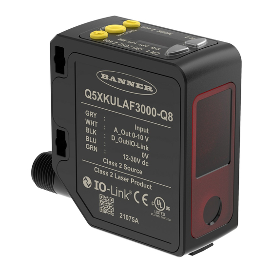
User selectable to be fixed or PNP connector NPN or PNP Overview The Q5X Laser Triangulation Sensor with Dual Mode for Jam Detection is a Class 2 laser CMOS sensor with a multifunction input and output. The Q5X with Jam Detection looks for a change in signal strength and distance between the face for the sensor and the packages. Because it does not rely on gaps, it detects jams faster and more accurately than conventional jam photo eyes. From Run mode, users may change the switch point value and channel selection and perform the selected TEACH method. -
Page 6: Class 2 Laser Description And Safety Information
CLASS 2 LASER PRODUCT IEC 60825-1:2007. Wavelength 640-670nm; 1.0mW max. Complies with Pulse Duration: 20 µs to 2 ms 21 CFR 1040.10 and 1040.11 except for deviations pursuant to Laser Notice No. 50, dated June 24, 2007. July 10, 2023 © Banner Engineering Corp. -
Page 7: Features
Q5X Laser Triangulation Sensor With Dual Mode And IO-Link For Jam Detection Instruction Manual Features The Q5X Laser Triangulation Sensor with Dual Mode for Jam Detection has three major features. Q5X Features Two output indicators (amber) Display Buttons Display and Indicators The display is a 4-digit, 7-segment LED. Run mode is the primary view displayed. For JRET, JBGS, 2-pt, BGS, FGS, and DYN TEACH modes, the display shows the current distance to the target in centimeters. For Dual TEACH mode, the display shows the percentage matched to the taught reference surface. A display value of ... - Page 8 Press to navigate the sensor menu in Setup mode Press to change setting values; press and hold to increase numeric values Press and hold for longer than 2 seconds to switch between Channel 1 and Channel 2 NOTE: When navigating the menu, the menu items loop. July 10, 2023 © Banner Engineering Corp.
-
Page 9: Chapter 2 Installation
For the minimum object separation distance required for each case, refer to "Performance Curves " on page 44. Orientation by a wall Orientation for a moving object Orientation for a height difference Continued on page 10 July 10, 2023 © Banner Engineering Corp. -
Page 10: Mount The Device
NOTE: The Channel 2 wire function and polarity is user-selectable. The default for the wire is PNP output. Applying tilt to sensor may improve performance on reflective targets. The direction and magnitude of the tilt depends on the application, but a 15° tilt is often sufficient. July 10, 2023 © Banner Engineering Corp. -
Page 11: Cleaning And Maintenance
MQDEC3-503SS MQDEC3-506SS MQDEC3-515SS MQDEC3-530SS Flying Lead Shielded Double Ended Sensor Pin 2 to Pin 5 MQDC-4501SS MQDEC2-506 MQDC-4506SS MQDEC2-515 RSD1 MQDEC2-530 Use these cordsets to connect the RSD1 to the Q5X sensor. July 10, 2023 © Banner Engineering Corp. - Page 12 Pinout (Female) MQDEC2-506 2 m (6.56 ft) 44 Typ. 5 m (16.4 ft) MQDEC2-515 MQDEC2-530 9 m (29.5 ft) Straight 1 = Brown MQDEC2-550 15 m (49.2 ft) M12 x 1 2 = White ø 14.5 3 = Blue MQDEC2-575 23 m (75.44 ft) 4 = Black MQDEC2-5100 30.5 m (100 ft) 5 = Gray Continued on page 13 July 10, 2023 © Banner Engineering Corp.
-
Page 13: Button Map From Rsd1 To Sensor
MQDEC2-5100RA 31 m (101.68 ft) Button Map from RSD1 to Sensor The sensor may be optionally connected to the Banner RSD1 remote display accessory. Refer to this table for the RSD1 button association with your sensor. Button association between the RSD1 and the Q4X/Q5X sensors Device ... - Page 14 Blank page ...
-
Page 15: Chapter 3 Sensor Programming
Setup Mode Access Setup mode and the sensor menu from Run mode by pressing and holding MODE for longer than 2 seconds. Use + and - to navigate through the menu. Press SELECT to select a menu option and access the submenus. Use + and - to navigate through the submenus. Press SELECT to select a submenu option and return to the top menu, or press and hold SELECT for longer than 2 seconds to select a submenu option and return immediately to Run mode. To exit Setup mode and return to Run mode, navigate to End and press SELECT. NOTE: The number that follows a menu option, for example tch1, indicates the channel that is selected. For menu items without a number (excluding submenu items), these menu options are only available from Channel 1 and the settings apply to both channels. July 10, 2023 © Banner Engineering Corp. - Page 16 Q5X Laser Triangulation Sensor With Dual Mode And IO-Link For Jam Detection Instruction Manual Sensor Menu Map—Channel 1 July 10, 2023 © Banner Engineering Corp.
- Page 17 Q5X Laser Triangulation Sensor With Dual Mode And IO-Link For Jam Detection Instruction Manual Sensor Menu Map—Channel 2 July 10, 2023 © Banner Engineering Corp.
-
Page 18: Output (Out1 And Out2)
Increase or decrease the time based on the speed of the conveyor and the length of the longest target. The default time is 2 seconds and is suitable for most applications. If the time needs to be increased, Banner recommends setting the Time Selection equal to the amount of time it takes two of the longest packages to pass back to back in front of the sensor. ... -
Page 19: Adaptive Tracking (Trc1 And Trc1)
Stabilize the reference surface to avoid this problem. Window Size (und1 and und2) Use this menu to manually set a window size for subsequent TEACH operations. This menu is available only if one-point window (foreground suppression) mode or jam retroreflective mode is selected. The default selection is Auto, where the foreground suppression (FGS) window size is automatically calculated. July 10, 2023 © Banner Engineering Corp. -
Page 20: Background Suppression (Bgs1 And Bgs2)
Time (D = 1ms - 90.0s) When one of the timing delay options is chosen, the sensor returns to the Setup menu and additional options become available to set the parameter(s): • —On delay • —Off delay July 10, 2023 © Banner Engineering Corp. -
Page 21: Zero Reference Location (Zero)
Shift the Zero Reference Location after a TEACH (ShFt) Use this menu to select whether the sensor shifts the zero-reference location based on the last TEACH process. The default is oFF, 0 = the front of the sensor or the maximum range. This menu is not available in dual (intensity + distance) mode. • —Shift the zero-reference location to one of the taught positions with each TEACH • —0 = the front of the sensor or the maximum range, depending on the ZEro setting July 10, 2023 © Banner Engineering Corp. -
Page 22: Offset (Ofs1 And Ofs2)
Use this menu to set an offset from the taught surface during a TEACH procedure. This menu is available only if one-point window (foreground suppression) mode, one-point background suppression mode, jam retroreflective mode, or jam background suppression mode is selected. For Channel 2, the output must be set to light operate or dark operate. NOTE: The number that follows on the display indicates which channel is selected. The offset is automatically calculated or manually defined as a consistently applied value. Auto is the default option. Use +/- to select a value. Values increase or decrease by up to 191 cm (2000 mm models). For BGS mode, the default is Auto because the Q5X automatically selects where to position the switch point. For FGS mode, the default is 0 because the window is centered around the taught target. A positive offset value always shifts the switch point location or the FGS window towards the sensor. July 10, 2023 © Banner Engineering Corp. -
Page 23: Display View (Disp)
Shift the Zero Reference Location after a TEACH ( ) —0 = the front of the sensor CH1 TEACH Mode ( ) —Jam Retroreflective CH2 TEACH Mode ( ) —Jam Background Suppression Zero Reference Location ( ) —Measurement increases further from sensor Display Units ( ) —Centimeters Output Polarity ( ) —Default: Push-pull on pin 4 and PNP on pin 2 July 10, 2023 © Banner Engineering Corp. -
Page 24: Manual Adjustments
Remote Input Use the remote input to program the sensor remotely. Remote input is available from the Channel 2 menu. Set Out2 to Set. The remote input provides limited programming options. The remote input is either Active High or Active Low depending on the polarity setting. If the polarity is set to def or PNP, the remote input is Active High. If polarity is set to NPN, the remote input is Active Low. For Active High, connect the white wire to 24 V DC with a remote switch connected between the wire and 24 V DC. For Active Low, connect the white wire to ground (0 V DC) with a remote switch connected between the wire and ground. Pulse the remote input according to the diagram and the instructions provided in this manual. The length of the individual programming pulses is equal to the value T: 0.04 seconds ≤ T ≤ 0.8 seconds. Exit remote programming modes by activating the remote input for longer than 2 seconds. July 10, 2023 © Banner Engineering Corp. -
Page 25: Select The Teach Mode Using The Remote Input
TEACH Mode 1 Jam retroreflective 2 Jam background suppression The selected TEACH method displays for a few seconds and the sensor returns to Run mode. Pulses TEACH Mode 1 Two-point TEACH 2 One-point TEACH July 10, 2023 © Banner Engineering Corp. -
Page 26: Reset To Factory Defaults Using The Remote Input
displays. Lock or unlock the sensor buttons. Action Result displays and the sensor returns to Single-pulse the remote input to unlock the sensor. Run mode. displays and the sensor returns to Double-pulse the remote input to lock the sensor. Run mode. Triple-pulse the remote input to apply the operator displays and the sensor returns to lock to the sensor Run mode July 10, 2023 © Banner Engineering Corp. -
Page 27: Teach Procedures
Result Push Button Press TEACH to teach the target. The sensor is taught the first target. SEt, 2nd, and the current distance measurement flash alternately on the Remote Input Single-pulse the remote input. display. The FLO, RET, and BGS indicators flash. July 10, 2023 © Banner Engineering Corp. -
Page 28: Dynamic Background Suppression (Dyn)
Dynamic Background Suppression NOTE: The sensor must be set to tch = dYn to use the following instructions. The FLO and RET indicators are amber to indicate Dynamic TEACH mode. July 10, 2023 © Banner Engineering Corp. - Page 29 Sets a switch point in front of the furthest taught distance Two valid distances that are less than the bGS and the switch point distance flash equal to the uniform reflectivity minimum object horizontal minimum object separation alternately on the display. separation. Continued on page 30 July 10, 2023 © Banner Engineering Corp.
-
Page 30: One-Point Window (Foreground Suppression) (Fgs)
NOTE: To program the sensor using remote input, remote input must be enabled (out2 = SEt). Present the target. Method Action Result Push Button Present the target. The sensor-to-target distance must be within the sensor's The target's measurement value displays. range. Remote Input Start the TEACH mode. July 10, 2023 © Banner Engineering Corp. -
Page 31: One-Point Background Suppression (Bgs)
One-Point Background Suppression (bGS) One-point background suppression sets a single switch point in front of the taught target distance. Objects beyond the taught switch point are ignored. The switch point is set in front of the taught target distance by the vertical minimum object separation. See "Performance Curves " on page July 10, 2023 © Banner Engineering Corp. - Page 32 Remote Input No action is required. N/A Teach the sensor. Method Action Result Push Button Press TEACH to teach the target. The new switch point flashes rapidly and the sensor returns to Run mode. Remote Input Single-pulse the remote input. See "Performance Curves " on page 44 for the minimum object separation. July 10, 2023 © Banner Engineering Corp.
-
Page 33: Dual (Intensity + Distance) (Dual)
Start the TEACH mode. Method Action Result Light Operate: SEt and on flash on the display. The RET, FLO, and BGS indicators flash. Push Button Press and hold the TEACH button for more than 2 seconds. Dark Operate: SEt and oFF flash on the display. The RET, FLO, and BGS indicators flash. No action is required. N/A Remote Input Teach the sensor. July 10, 2023 © Banner Engineering Corp. -
Page 34: Jam Retroreflective (Jret)
NOTE: To program the sensor using remote input, remote input must be enabled ( = ). Present the target. Method Action Result Push Button Present the target. The sensor-to-target distance must be within the sensor's The target's measurement value displays. range. Remote Input Start the TEACH mode. July 10, 2023 © Banner Engineering Corp. -
Page 35: Jam Background Suppression (Jbgs)
This TEACH mode does not require a stationary target for a reference point. Manually adjust the background suppression point using the bGS1/bGS2 menu. Measurements beyond the taught point are qualified as not jammed. An independent jam range (RNG) value is set which defines the minimum movement required to determine that an object is moving (not jammed). A Loss of Signal condition is not treated as a jam. July 10, 2023 © Banner Engineering Corp. - Page 36 Remote Input No action required. N/A Teach the sensor. Method Action Result Push Button Press TEACH to teach the target. The new switch point flashes rapidly and the sensor returns to Run mode. Remote Input Single-pulse the remote input. See "Performance Curves " on page 44 for the minimum object separation. July 10, 2023 © Banner Engineering Corp.
-
Page 37: Pulse Frequency Modulation (Pfm) Output (Puls)
IMPORTANT: The master sensor and the slave sensor must be programmed for the same Response Speed and Gain and Sensitivity settings. The master sensor and slave sensor must share a common power source. Configure the first sensor as the master; navigate to: inPt › nASt. Configure the second sensor as the slave; navigate: inPt › SLUE. Connect the white wires of the two sensors together. July 10, 2023 © Banner Engineering Corp. - Page 38 Blank page ...
-
Page 39: Chapter 4 Io-Link Interface
Master AOI is to translate the desired IO-Link read/write requests, made by the Parameter Data AOI, into the format a specific IO-Link Master requires. Each IO-Link Master AOI is customized for a given brand of IO-Link Master. Add and configure the relevant Banner IO-Link Master AOI in your ladder logic program first; then add and configure Banner IO-Link Device AOIs as desired, linking them to the Master AOI as shown in the relevant AOI documentation. ... - Page 40 Blank page ...
-
Page 41: Chapter 5 Specifications
Supply Supply Required Overcurrent Required Overcurrent Wiring Wiring Protection (A) Protection (A) (AWG) (AWG) Boresighting ± 43 mm at 2000 mm Response Speed User selectable: 15, 25, or 50 ms Delay at Power Up < 2.5 s July 10, 2023 © Banner Engineering Corp. - Page 42 70 (25) 15 (6) 25 1250 (800) 450 (250) 125 (70) 30 (15) 50 2500 (1250) 900 (450) 250 (125) 60 (30) Standard excess gain available in 15, 25, and 50 ms response speeds; standard excess gain provides increase noise immunity. July 10, 2023 © Banner Engineering Corp.
-
Page 43: Fcc Part 15 Class A
(2) il doit tolérer toute interférence, y compris celles susceptibles de provoquer un fonctionnement non souhaité du dispositif. Dimensions All measurements are listed in millimeters [inches], unless noted otherwise. SCALE SCALE SCALE RECEIVED LIGHT EMITTED LIGHT July 10, 2023 © Banner Engineering Corp. -
Page 44: Performance Curves
Q5X Laser Triangulation Sensor With Dual Mode And IO-Link For Jam Detection Instruction Manual Performance Curves Minimum Object Separation Distance (90% to 6% reflectance) 1000 1200 1400 1600 1800 2000 Distance to Target (mm) Dimension X Background Switch Point Distance July 10, 2023 © Banner Engineering Corp. -
Page 45: Chapter 6 Additional Information
Output switches with intensity and distance change Output switches with intensity and/or second peak (Clear Object Detection) The Q5X sensor can be taught non-ideal reference surfaces, such as surfaces outside of the sensor’s range, very dark surfaces, or even empty space. These situations may enable applications requiring a long range detection but are subject to typical diffuse mode detection challenges. July 10, 2023 © Banner Engineering Corp. -
Page 46: Dual Mode Reference Surface Considerations
Dual Mode Reference Surface Considerations Optimize reliable detection by applying these principles when selecting your reference surface, positioning your sensor relative to the reference surface, and presenting your target. The robust detection capabilities of the Q5X allows successful detection even under non-ideal conditions in many cases. Typical reference surfaces are metal machine frames, conveyor side rails, or mounted plastic targets. Contact Banner Engineering if you require assistance setting up a stable reference surface in your application. Select a reference surface with these characteristics where possible: ◦... -
Page 47: Abbreviations
Move the target closer to the sensor Common problems and solutions for detecting clear objects—Sensor too far PROBLEM: SOLUTION: The sensor is far from the object Move the sensor closer to the target Abbreviations The following table describes the abbreviations used on the sensor display and in this manual. Abbreviation Description No valid signal in range The sensor has not been taught One-shot Continued on page 48 July 10, 2023 © Banner Engineering Corp. - Page 48 One-point window (foreground suppression) Full range Excess gain High excess gain mode High speed tracking Hysteresis Jam background suppression Jam retroreflective Light operate Laser on Lock/locked Laser off Master Continued on page 49 July 10, 2023 © Banner Engineering Corp.
- Page 49 Slave Response speed Standard excess gain mode Start Stop TEACH process selection (Channel 1, Channel 2) , Totalizer Total counts , Unlock/unlocked Unit Saturated signal (too much light) Window size (Channel 1, Channel 2) , Yes Zero—select the zero reference location July 10, 2023 © Banner Engineering Corp.
- Page 50 Blank page ...
-
Page 51: Chapter 7 Accessories
Swivel bracket with tilt and pan movement for precision adjustment • Easy sensor mounting to extruded rail T-slots • Metric and inch size bolts are available 3X M3X0.5 • Side mounting of some sensors with the 3 mm screws included 3X M4X0.7 with the sensor Continued on page 52 July 10, 2023 © Banner Engineering Corp. - Page 52 • Clamp bracket mounts to sensor dovetail • Translation adjustment for sensor alignment • Aluminum clamp - 6.5mm maximum plate thickness SMBAMSQ5XP • Flat SMBAMS series bracket • Articulation slots for 30 deg rotation • 13-ga. 304 stainless steel Ø6.5 2X R3.4 SMBAMSQ5XRA • Right-angle SMBAMS series bracket • Articulation slots for 30 deg rotation Ø6.7 • 13-ga. 304 stainless steel 2X R3.4 July 10, 2023 © Banner Engineering Corp.
-
Page 53: Reference Targets
• FDA grade acetal material RSD1 Remote Display Use the optional RSD1 for remote monitoring and configuring compatible devices. Refer to the RSD1 instruction manual (p/n 199621) or quick start guide (p/n 199622) for more information. See "Accessories" on page 51 for the required cordsets. RSD1 Remote Display Model Output A and B Dimensions Male Wiring 78.0 [3.07] Brown White Blue 28.0 RSD1QP Configurable [1.10] Black Gray 68.0 [2.68] July 10, 2023 © Banner Engineering Corp. - Page 54 Blank page ...
-
Page 55: Chapter 8 Product Support And Maintenance
Banner Engineering Corp. warrants its products to be free from defects in material and workmanship for one year following the date of shipment. Banner Engineering Corp. will repair or replace, free of charge, any product of its manufacture which, at the time it is returned to the factory, is found to have been defective during the warranty period. - Page 56 WHETHER ARISING IN CONTRACT OR WARRANTY, STATUTE, TORT, STRICT LIABILITY, NEGLIGENCE, OR OTHERWISE. Banner Engineering Corp. reserves the right to change, modify or improve the design of the product without assuming any obligations or liabilities relating to any product previously manufactured by Banner Engineering Corp. Any misuse, abuse, or improper application or installation of this product or use of the product for personal protection applications when the product is identified as not intended for such purposes will void the product warranty.
- Page 57 LinkedIn Twitter Facebook © 2023. All rights reserved. www.bannerengineering.com...
- Page 58 Mouser Electronics Authorized Distributor Click to View Pricing, Inventory, Delivery & Lifecycle Information: Banner Engineering SMBQ4XFAM10 SMBQ5XFA SMBQ5XFAM12...
Need help?
Do you have a question about the Q5X and is the answer not in the manual?
Questions and answers