Banner Q5X Manual
Laser measurement sensor with dual discrete outputs and io-link
Hide thumbs
Also See for Q5X:
- Instruction manual (61 pages) ,
- Quick start manual (17 pages) ,
- Reference manual (7 pages)
Table of Contents
Advertisement
Quick Links
Q5X Laser Measurement Sensor with Dual
Discrete Outputs and IO-Link
Quick Start Guide
Laser sensor with dual outputs and IO-Link
This guide is designed to help you set up and install the Q5X Laser Measurement Sensor. For complete information on
programming, performance, troubleshooting, dimensions, and accessories, please refer to the Instruction Manual at
www.bannerengineering.com. Search for p/n 208794 to view the Instruction Manual. Use of this document assumes familiarity with
pertinent industry standards and practices.
WARNING:
•
Do not use this device for personnel protection
•
Using this device for personnel protection could result in serious injury or death.
•
This device does not include the self-checking redundant circuitry necessary to allow its use in
personnel safety applications. A device failure or malfunction can cause either an energized (on) or de-
energized (off) output condition.
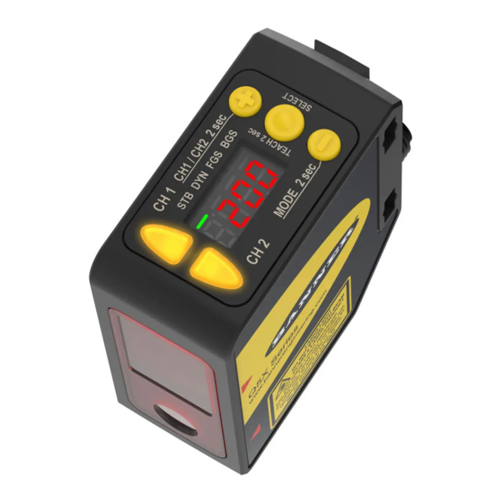
Features
The Q5X has three major features.
Figure 1. Q5X Features
2
1
Display and Indicators
The display is a 4-digit, 7-segment LED. Run mode is the primary view displayed.
For 2-pt, BGS, FGS, and DYN TEACH modes, the display shows the current distance to the target in centimeters. For Dual TEACH
mode, the display shows the percentage matched to the taught reference surface. A display value of
has not been taught.
Figure 2. Display in Run Mode
1
STB DYN FGS BGS
Output Indicator
•
On—Output is on
•
Off—Output is off
Stability Indicator (STB)
•
On—Stable signal within the specified sensing range
•
Flashing—Marginal signal (low excess gain), the target
is outside the limits of the specified sensing range, or a
multiple peak condition exists
•
Off—No target detected within the specified sensing
range
Original Document
208795 Rev. G
3
2
1. Stability Indicator (STB—Green)
2. Active TEACH Indicators
•
DYN—Dynamic (Amber)
•
FGS—Foreground Suppression (Amber)
•
BGS—Background Suppression (Amber)
10 January 2023
1. Two output indicators (amber)
2. Display
3. Buttons
Active TEACH Indicators (DYN, FGS, and BGS)
•
DYN, FGS, and BGS all off—Two-point TEACH mode
selected (default)
•
DYN on—Dynamic TEACH mode selected
•
FGS on—Foreground suppression TEACH mode
selected
•
BGS on—Background suppression TEACH mode
selected
•
DYN, FGS, and BGS all on—Dual TEACH mode
selected
indicates the sensor
208795
Advertisement
Table of Contents

Related Manuals for Banner Q5X


Summary of Contents for Banner Q5X
- Page 1 Laser sensor with dual outputs and IO-Link This guide is designed to help you set up and install the Q5X Laser Measurement Sensor. For complete information on programming, performance, troubleshooting, dimensions, and accessories, please refer to the Instruction Manual at www.bannerengineering.com.
- Page 2 Q5X Laser Measurement Sensor with Dual Discrete Outputs and IO-Link Buttons Use the sensor buttons (SELECT)(TEACH), (+)(CH1/CH2), and (-)(MODE) to program the sensor. Figure 3. Button Layout (SELECT)(TEACH) (+)(CH1/CH2) • Press to select menu items in Setup mode • Press to navigate the sensor menu in Setup mode •...
-
Page 3: Mount The Device
See the following figures for examples of correct and incorrect sensor-to-target orientation as certain placements may pose problems for sensing some targets. The Q5X can be used in the less preferred orientation and at steep angles of incidence and still provide reliable detection performance due to its high excess gain. -
Page 4: Wiring Diagram
Q5X Laser Measurement Sensor with Dual Discrete Outputs and IO-Link 3. Check the device alignment. 4. Tighten the mounting screws to secure the device (or the device and the bracket) in the aligned position. Wiring Diagram Figure 12. Channel 2 as PNP Discrete or PFM Output Figure 13. - Page 5 Q5X Laser Measurement Sensor with Dual Discrete Outputs and IO-Link Connecting to RSD1 The following diagram depicts the connection of the Q5X to the optional RSD1 accessory. Figure 18. Q5X to RSD1 Double Ended Shielded MQDEC3-503SS MQDEC3-506SS MQDEC3-515SS MQDEC3-530SS Flying Lead Shielded...
-
Page 6: Sensor Programming
31 m (101.68 ft) Button Map from RSD1 to Sensor The sensor may be optionally connected to the Banner RSD1 remote display accessory. Refer to this table for the RSD1 button association with your sensor. Table 1: Button association between the RSD1 and the Q4X/Q5X sensors... - Page 7 Q5X Laser Measurement Sensor with Dual Discrete Outputs and IO-Link Note: The number that follows a menu option, for example , indicates the channel that is selected. For menu items without a number (excluding submenu items), these menu options are only available from Channel 1 and the settings apply to both channels.
- Page 8 Q5X Laser Measurement Sensor with Dual Discrete Outputs and IO-Link Figure 20. Sensor Menu Map—Channel 2 Channel 2 Top Menu Sub Menu Output CH2 Light Operate default setting Dark Operate Complimentary to Output 1 set: Remote Teach input laser off when pulled high...
-
Page 9: Manual Adjustments
Q5X Laser Measurement Sensor with Dual Discrete Outputs and IO-Link Basic TEACH Instructions Use the following instructions to teach the Q5X sensor. The instructions provided on the sensor display vary depending on the type of TEACH mode selected. Two-point TEACH is the default TEACH mode. -
Page 10: Specifications
Q5X Laser Measurement Sensor with Dual Discrete Outputs and IO-Link When in mode, displays when (-)(MODE) is pressed and held. To access the manual adjust options, briefly press and release (+)(CH1/CH2) or (-)(MODE). To enter TEACH mode, press the (SELECT)(TEACH) button and hold for longer than 2 seconds. - Page 11 Q5X Laser Measurement Sensor with Dual Discrete Outputs and IO-Link Output Rating Current rating: 50 mA maximum Black wire specifications per configuration Output High: ≥ Vsupply - 2.5 V IO-Link Push/Pull Output Low: ≤ 2.5 V Output High: ≥ Vsupply - 2.5 V Output Low: ≤...
-
Page 12: Performance Curves
Q5X Laser Measurement Sensor with Dual Discrete Outputs and IO-Link Discrete Output Distance Repeatability Distance (mm) Repeatability (2000 mm Models) 95 to 300 ± 0.5 mm 300 to 1000 ± 0.25% 1000 to 2000 ± 0.5% See the charts for the Repeatability of the 5000 mm and 10000 mm models. - Page 13 Q5X Laser Measurement Sensor with Dual Discrete Outputs and IO-Link Figure 22. Typical performance curves for the 2000 mm models Matte targets with a non-uniform reflectivity: 6% to 90% Matte targets with uniform reflectivity: 6% to 90% 1000 1200 1400...
-
Page 14: Dual Mode Reference Surface Considerations
Banner Engineering Corp. Limited Warranty Banner Engineering Corp. warrants its products to be free from defects in material and workmanship for one year following the date of shipment. Banner Engineering Corp. will repair or replace, free of charge, any product of its manufacture which, at the time it is returned to the factory, is found to have been defective during the warranty period. This warranty does not cover damage or liability for misuse, abuse, or the improper application or installation of the Banner product.
Need help?
Do you have a question about the Q5X and is the answer not in the manual?
Questions and answers