Banner Q5X Quick Start Manual
Laser triangulation sensor with analog outputs
Hide thumbs
Also See for Q5X:
- Instruction manual (61 pages) ,
- Quick start manual (17 pages) ,
- Manual (15 pages)
Table of Contents
Advertisement
Quick Links
Q5X Laser Triangulation Sensor with Analog
Outputs
Quick Start Guide
Laser sensor with an analog output and IO-Link
This guide is designed to help you set up and install the Q5X Laser Triangulation Sensor. For complete information on programming,
performance, troubleshooting, dimensions, and accessories, please refer to the Instruction Manual at www.bannerengineering.com.
Search for p/n 219602 to view the Instruction Manual. Use of this document assumes familiarity with pertinent industry standards
and practices.
WARNING:
•
Do not use this device for personnel protection
•
Using this device for personnel protection could result in serious injury or death.
•
This device does not include the self-checking redundant circuitry necessary to allow its use in
personnel safety applications. A device failure or malfunction can cause either an energized (on) or de-
energized (off) output condition.
Features
2
1
Display and Indicators
The display is a four-digit, seven-segment LED. Run mode is the primary view displayed.
For 1-PT, 2-PT, BGS, FGS, and DYN TEACH modes, the display shows the current distance to the target in centimeters. For Dual
TEACH mode, the display shows the percentage matched to the taught reference surface. A display value of
sensor has not been taught.
Figure 1. Display in Run Mode
1
STB 2-PT 1-PT MM
Output Indicators
•
Ch1: On when the displayed distance is within the taught
analog output window
•
Ch2: On when the displayed distance is within the taught
discrete output window
Stability Indicator (STB)
•
On—Stable signal within the specified sensing range
•
Flashing—Marginal signal, the target is outside the limits
of the specified sensing range, or a multiple peak
condition exists
•
Off—No target detected within the specified sensing
range
Original Document
219603 Rev. A
3
1. Stability Indicator (STB—Green)
2
2. Active TEACH Indicators
•
•
3. Display value indicator (MM - Amber)
28 June 2021
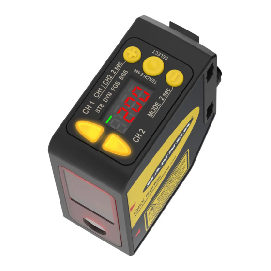
1. Two output indicators (amber)
2. Display
3. Buttons
2-PT - Two-Point TEACH (Amber)
1-PT - One-Point TEACH (Amber)
Active TEACH Indicators (2PT and 1PT)
•
2-PT on—Two-point TECH mode selected (default)
•
1-PT on—One-point TEACH mode selected
Display Value Indicator (MM)
•
On—Display shows the distance in millimeters (default)
•
Off—Display shows the analog output value
indicates the
219603
Advertisement
Table of Contents

Related Manuals for Banner Q5X


Summary of Contents for Banner Q5X
- Page 1 Laser sensor with an analog output and IO-Link This guide is designed to help you set up and install the Q5X Laser Triangulation Sensor. For complete information on programming, performance, troubleshooting, dimensions, and accessories, please refer to the Instruction Manual at www.bannerengineering.com.
- Page 2 Q5X Laser Triangulation Sensor with Analog Outputs Buttons Use the sensor buttons (SELECT)(TEACH), (+)(CH1/CH2), and (-)(MODE) to program the sensor. Figure 2. Q5X sensor face (SELECT)(TEACH) (+)(CH1/CH2) • Press to select menu items in Setup mode • Press to navigate the sensor menu in Setup mode •...
-
Page 3: Mount The Device
See the following figures for examples of correct and incorrect sensor-to-target orientation as certain placements may pose problems for sensing some targets. The Q5X can be used in the less preferred orientation and at steep angles of incidence and still provide reliable detection performance due to its high excess gain. -
Page 4: Sensor Programming
Button Map from RSD1 to Sensor The sensor may be optionally connected to the Banner RSD1 remote display accessory. Refer to this table for the RSD1 button association with your sensor. - Page 5 Q5X Laser Triangulation Sensor with Analog Outputs Figure 10. Sensor Menu Map—Channel 1 Channel 1 Top Menu Sub Menus Teach Process Selection Top Menu Sub Menus two-point teach default setting one-point teach Offset CH1 **** Response Speed CH1 & CH2...
- Page 6 Q5X Laser Triangulation Sensor with Analog Outputs Figure 11. Sensor Menu Map—Channel 2 Channel 2 Top Menu Sub Menu Output CH2 Light Operate Dark Operate default setting Teach Selection CH2 Two-Point Static Teach Menu items only available when Dynamic Teach...
-
Page 7: Basic Teach Instructions
Q5X Laser Triangulation Sensor with Analog Outputs Basic TEACH Instructions Use the following instructions to teach the Q5X sensor. The instructions provided on the sensor display vary depending on the type of TEACH mode selected. Two-point TEACH is the default TEACH mode. - Page 8 When lateral entry needs to be considered, the lateral entry response is added to calculate the total response time. Note: The Q5X uses a dynamic measurement rate, so these response times are worst-case. www.bannerengineering.com - Tel: + 1 888 373 6767...
-
Page 9: Specifications
Q5X Laser Triangulation Sensor with Analog Outputs Specifications Sensing Beam Boresighting IEC 60825-1:2014 ± 65 mm at 3000 mm Visible red Class 2 laser models, 650 nm Response Speed Supply Voltage (Vcc) Total response speed varies between 0.5 ms and 2270 ms, depending on base measurement rate and averaging settings. -
Page 10: Performance Curves
Q5X Laser Triangulation Sensor with Analog Outputs Required Overcurrent Protection Shock MIL-STD-202G, Method 213B, Condition I (100G 6x along X, Y, and Z axes, 18 shocks), with device operating WARNING: Electrical connections must be made by qualified personnel in accordance with... -
Page 11: Dual Mode Reference Surface Considerations
Optimize reliable detection by applying these principals when selecting your reference surface, positioning your sensor relative to the reference surface, and presenting your target. The robust detection capabilities of the Q5X allows successful detection even under non-ideal conditions in many cases. Typical reference surfaces are metal machine frames, conveyor side rails, or mounted plastic targets. - Page 12 Banner Engineering Corp. Limited Warranty Banner Engineering Corp. warrants its products to be free from defects in material and workmanship for one year following the date of shipment. Banner Engineering Corp. will repair or replace, free of charge, any product of its manufacture which, at the time it is returned to the factory, is found to have been defective during the warranty period. This warranty does not cover damage or liability for misuse, abuse, or the improper application or installation of the Banner product.
Need help?
Do you have a question about the Q5X and is the answer not in the manual?
Questions and answers