
Related Manuals for Banner Q5XKLAF2000-Q8


Summary of Contents for Banner Q5XKLAF2000-Q8
-
Page 1: Background Suppression
Q5X Laser Triangulation Sensor with Background Suppression Instruction Manual Original Instructions 208794 Rev. A 6 November 2018 © Banner Engineering Corp. All rights reserved 208794... -
Page 2: Table Of Contents
6.3 Dual Mode Considerations for Clear and Transparent Object Detection ..................35 6.4 Abbreviations ....................................36 7 Troubleshooting ................................39 8 Accessories ................................... 40 8.1 Cordsets ......................................40 8.2 Brackets ......................................40 8.3 Reference Targets ..................................41 9 Contact Us ..................................42 10 Banner Engineering Corp. Limited Warranty ......................44... -
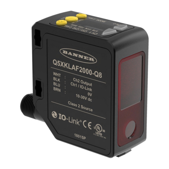
Page 3: Product Description
Connection PNP output or user selectable IO-Link, Push/pull output 270° rotatable Integral 4-pin multi-function 95 mm to 2000 mm (9.5 Q5XKLAF2000-Q8 M12/Euro-style quick User selectable to be fixed cm to 200 cm) User selectable to be fixed disconnect NPN or PNP NPN or PNP 1.2 Overview... -
Page 4: Features
Q5X Laser Triangulation Sensor with Background Suppression For Safe Laser Use - Class 2 Lasers • Do not stare at the laser. • Do not point the laser at a person’s eye. • Mount open laser beam paths either above or below eye level, where practical. •... -
Page 5: Buttons
Q5X Laser Triangulation Sensor with Background Suppression Output Indicator Active TEACH Indicators (DYN, FGS, and BGS) • On—Output is on • DYN, FGS, and BGS all off—Two-point TEACH mode selected (default) • Off—Output is off • DYN on—Dynamic TEACH mode selected Stability Indicator (STB) •... -
Page 6: Installation
Q5X Laser Triangulation Sensor with Background Suppression 2 Installation 2.1 Sensor Orientation Optimize detection reliability and minimum object separation performance with correct sensor-to-target orientation. To ensure reliable detection, orient the sensor as shown in relation to the target to be detected. Figure 3. -
Page 7: Wiring Diagram
Q5X Laser Triangulation Sensor with Background Suppression 2.3 Wiring Diagram 10-30V dc Load 10-30V dc Load – – Remote 1 = Brown Load Input 2 = White 3 = Blue Figure 9. Channel 2 as PNP Discrete or PFM Output Figure 10. -
Page 8: Sensor Programming
Q5X Laser Triangulation Sensor with Background Suppression 3 Sensor Programming Program the sensor using the buttons on the sensor or the remote input (limited programming options). In addition to programming the sensor, use the remote input to disable the buttons for security, preventing unauthorized or accidental programming changes. - Page 9 Q5X Laser Triangulation Sensor with Background Suppression Channel 1 Top Menu Sub Menu default setting) Output CH1 Light Operate Dark Operate Teach Selection CH1 Two-Point Static Teach Dynamic Teach Foreground Suppression Background Suppression Dual Mode Adaptive Tracking CH1 * on: Adaptive Tracking on off: Adaptive Tracking off High-Speed Adaptive Tracking on Adaptive Tracking menu is available when Teach CH1 is set to Dual Mode...
- Page 10 Q5X Laser Triangulation Sensor with Background Suppression Channel 2 Top Menu Sub Menu Output CH2 Light Operate default setting) Dark Operate Complimentary to Output 1 set: Remote Teach input laser off when pulled high laser on when pulled high master slave pulse Teach Selection CH2...
-
Page 11: Output
Q5X Laser Triangulation Sensor with Background Suppression 3.2.1 Output Note: The number that follows out on the display indicates which channel is selected. The Output 1 menu is available in Channel 1. Use this menu to select light operate (LO) or dark operate (DO). The default output configuration is light operate. -
Page 12: Window Size
Q5X Laser Triangulation Sensor with Background Suppression Note: The number that follows trc on the display indicates which channel is selected. • —High-Speed Adaptive Tracking On • —Adaptive Tracking On • —Adaptive Tracking Off (default) OFF disables the Adaptive Tracking Algorithm—Prevents the sensor from adjusting the thresholds around the taught reference surface while the sensor is in dual mode. -
Page 13: Gain And Sensitivity
Q5X Laser Triangulation Sensor with Background Suppression 3.2.6 Gain and Sensitivity Use this menu to set the excess gain mode. This menu is only available when a 15, 25, or 50 millisecond response speed is selected. It is not available for 3 or 5 millisecond response speeds. •... -
Page 14: Hysteresis And
Q5X Laser Triangulation Sensor with Background Suppression Delay Timers Use these menus to set the delay timers. These menus are available only if an output timing delay is selected. , the default is 0. , the defaults are: • 10 milliseconds for 15, 25, and 50 millisecond response speeds •... -
Page 15: Zero Reference Location
Q5X Laser Triangulation Sensor with Background Suppression Rated Sensing Distance Set Distance Hysteresis (Differential Travel)—With respect to the distance between the standard sensing object and the sensor, the difference between the distance at which the sensor operates and the distance at which the sensor resets. Sensing Distance Reset... -
Page 16: Offset
Q5X Laser Triangulation Sensor with Background Suppression • —0 = the front of the sensor or the maximum range, depending on the setting This figure illustrates three examples of how changes to the zero and shift settings affect what distance readout is shown on the display when in 2-pt TEACH mode. -
Page 17: Display View
Q5X Laser Triangulation Sensor with Background Suppression The taught surface must be inside of the defined sensing range. When the teach mode is set to FGS, some portion of the window must be located within the sensing range. When the teach mode is set to BGS, the offset value must be within the defined sensing range. -
Page 18: Manual Adjustments
Q5X Laser Triangulation Sensor with Background Suppression Setting Factory Default TEACH Mode ( —Two-point TEACH Zero Reference Location ( —Measurement increases further from sensor Hysteresis ( —Sensor controls value Display Units ( —Centimeters Output Polarity ( —Default: IO-Link on pin 4 and PNP on pin 2 3.3 Manual Adjustments Manually adjust the sensor switch point using the buttons. -
Page 19: Select The Teach Mode Using The Remote Input
Q5X Laser Triangulation Sensor with Background Suppression Remote Input Wire Function = Set Pulse Timing (T) Input Gray wire is remote teach input 0.04 seconds < T < 0.8 seconds Timing between Pulse groups > 1 second Starts selected Teach (same function as pressing Teach Button for > 2 sec) Second pulse completes Teach (Two-point, Dynamic Teach and Dual Mode only) Teach Selection Two-point static background suppression... -
Page 20: Reset To Factory Defaults Using The Remote Input
Q5X Laser Triangulation Sensor with Background Suppression 3.4.2 Reset to Factory Defaults Using the Remote Input Eight-pulse the remote input to apply the factory defaults and return to Run mode. Note: The input wire function remains at remote teach input ( 3.5 Locking and Unlocking the Sensor Buttons Use the lock and unlock feature to prevent unauthorized or accidental programming changes. -
Page 21: Teach Procedures
Q5X Laser Triangulation Sensor with Background Suppression 3.6 TEACH Procedures Use the following procedures to teach the sensor. To cancel a TEACH procedure, press TEACH for longer than 2 seconds, or hold the remote input high for longer than 2 seconds. -
Page 22: Dynamic Background Suppression
Q5X Laser Triangulation Sensor with Background Suppression 4. Present the target. Method Action Result Push Button , and the distance Present the second target. The sensor-to-target distance must be within the measurement flash alternately on the sensor's range. display. The DYN, FGS, and BGS Remote Input indicators flash. - Page 23 Q5X Laser Triangulation Sensor with Background Suppression Note: To program the sensor using remote input, remote input must be enabled ( 1. Present the target. Method Action Result Push Button Present the first target. The sensor-to-target distance must be within the The target's measurement value displays.
-
Page 24: One-Point Window (Foreground Suppression)
Q5X Laser Triangulation Sensor with Background Suppression 3.6.3 One-Point Window (Foreground Suppression) One-point window sets a window (two switch points) centered around the taught target distance. Loss of signal is treated as a detection in One-Point Window mode. The size of the taught window is the vertical minimum object separation. See Figure 24 on page 33. -
Page 25: One-Point Background Suppression
Q5X Laser Triangulation Sensor with Background Suppression Table 4: Expected TEACH Behavior for One-Point Window (Foreground Suppression) Figure 24 on page 33 for the minimum object separation. Condition TEACH Result Display One valid TEACH point with both switch Sets a window (two switch points) centered around the The ±... -
Page 26: Dual (Intensity + Distance)
Q5X Laser Triangulation Sensor with Background Suppression Method Action Result Light Operate flash alternately on the display. The BGS indicator flashes. Push Button Press and hold TEACH for longer than 2 seconds. Dark Operate flash alternately on the display. The BGS indicator flashes. Remote Input No action required. -
Page 27: Pulse Frequency Modulation (Pfm) Output
Q5X Laser Triangulation Sensor with Background Suppression 1. Present the target. Method Action Result Push Button Present the reference target. The target's match percentage displays Remote Input 2. Start the TEACH mode. Method Action Result Light Operate: flash on the display. The DYN, FGS, and BGS indicators flash. - Page 28 Q5X Laser Triangulation Sensor with Background Suppression Important: The master sensor and the slave sensor must be programmed for the same Response Speed and Gain and Sensitivity settings. The master sensor and slave sensor must share a common power source. 1.
-
Page 29: Io-Link Interface
IO‐Link Master requires. Each IO‐Link Master AOI is customized for a given brand of IO‐Link Master. Add and configure the relevant Banner IO‐Link Master AOI in your ladder logic program first; then add and configure Banner IO‐Link Device AOIs as desired, linking them to the Master AOI as shown in the relevant AOI documentation. -
Page 30: Specifications
Q5X Laser Triangulation Sensor with Background Suppression 5 Specifications Sensing Beam Response Speed Visible red, Class 2 laser, 650 nm User selectable: 3, 5, 15, 25, or 50 ms Supply Voltage (Vcc) Delay at Power Up 10 to 30 V dc (Class 2 supply) (10% max ripple within limits) <... - Page 31 Q5X Laser Triangulation Sensor with Background Suppression Required Overcurrent Protection Shock MIL-STD-202G, Method 213B, Condition I (100G 6x along X, Y and Z axes, 18 shocks), with sensor operating WARNING: Electrical connections must be made by qualified personnel in accordance Operating Conditions with local and national electrical codes and –10 °C to +50 °C (+14 °F to +122 °F)
-
Page 32: Dimensions
Q5X Laser Triangulation Sensor with Background Suppression 5.1 Dimensions All measurements are listed in millimeters [inches], unless noted otherwise. www.bannerengineering.com - Tel: +1.763.544.3164... -
Page 33: Performance Curves
Q5X Laser Triangulation Sensor with Background Suppression 5.2 Performance Curves Matte targets with a non-uniform reflectivity: 6% to 90% Matte targets with uniform reflectivity: 6% to 90% 1000 1200 1400 1600 1800 2000 Distance to Target (mm) Dimension X Figure 24. Minimum Object Separation Distance (90% to 6% reflectance) www.bannerengineering.com - Tel: +1.763.544.3164... -
Page 34: Additional Information
The robust detection capabilities of the Q5X allows successful detection even under non-ideal conditions in many cases. Typical reference surfaces are metal machine frames, conveyor side rails, or mounted plastic targets. Contact Banner Engineering if you require assistance setting up a stable reference surface in your application. -
Page 35: Dual Mode Considerations For Clear And Transparent Object Detection
Q5X Laser Triangulation Sensor with Background Suppression 6.3 Dual Mode Considerations for Clear and Transparent Object Detection The Q5X is able to detect the very small changes caused by transparent and clear objects. A transparent object can be detected either by a change in intensity, distance, or by a double-peak reflection. The Q5X sensor can be taught non-ideal reference surfaces, such as surfaces outside of the sensor range or very dark surfaces. -
Page 36: Abbreviations
Q5X Laser Triangulation Sensor with Background Suppression PROBLEM: SOLUTION: The object is close to the reference surface Move the target closer to the sensor PROBLEM: SOLUTION: The sensor is far from the object Move the sensor closer to the target Figure 27. - Page 37 Q5X Laser Triangulation Sensor with Background Suppression Abbreviation Description Dark operate Delay timer (Channel 1, Channel 2) Dual mode Dynamic background suppression End—exit the sensor menu Far zero reference location—the maximum range is 0 and the measurement increase as the target moves closer to the sensor One-point window (foreground suppression) Full range...
- Page 38 Q5X Laser Triangulation Sensor with Background Suppression Abbreviation Description Shift the Zero Reference Location after a TEACH Slave Response speed Standard excess gain mode Start Stop TEACH process selection (Channel 1, Channel 2) Totalizer Total counts Unlock/unlocked Unit Saturated signal (too much light) Window size (Channel 1, Channel 2) Zero—select the zero reference location www.bannerengineering.com - Tel: +1.763.544.3164...
-
Page 39: Troubleshooting
Reposition the sensor or the target to increase the detection distance, or increase the angle of incidence between the sensor and the target EEPROM fault Contact Banner Engineering to resolve Laser fault Contact Banner Engineering to resolve Output short-circuited Check the wiring for an electrical short... -
Page 40: Accessories
Q5X Laser Triangulation Sensor with Background Suppression 8 Accessories 8.1 Cordsets 4-Pin Threaded M12/Euro-Style Cordsets Model Length Style Dimensions Pinout (Female) MQDC-406 1.83 m (6 ft) 44 Typ. MQDC-415 4.57 m (15 ft) Straight MQDC-430 9.14 m (30 ft) M12 x 1 ø... -
Page 41: Reference Targets
Q5X Laser Triangulation Sensor with Background Suppression SMBQ5XDT SMBAMSQ5XP M4 X M4 X 0.7 • Clamp bracket mounts • Flat SMBAMS series 0.7 X 16 mm 5X M4 X 0.7 ISO-6H X 12mm TAP THRU to sensor dovetail bracket • Translation adjustment •... -
Page 42: Contact Us
Park Lane, Culliganlaan 2F, bus 3 Email: mail@bannerengineering.com 1831 Diegem, Belgium Turkey Address: Phone: +90 216 688 8282 Banner Engineering Elk. San. Ve Tic. Ltd. Şti. Website: www.bannerengineering.com Şerifali Mah. Münevver Sok. Ekomed Plaza No:10 Kat:4 Email: turkey@bannerengineering.com.tr Ümraniye / İstanbul, Türkiye... - Page 43 Q5X Laser Triangulation Sensor with Background Suppression Taiwan Address: Phone: +886 (0)2 8751 9966 Banner Engineering Taiwan Website: www.bannerengineering.com 8F-2, No. 308 Section 1, Neihu Road Email: info@bannerengineering.com.tw Taipei 114, Taiwan www.bannerengineering.com - Tel: +1.763.544.3164...
-
Page 44: Banner Engineering Corp. Limited Warranty
10 Banner Engineering Corp. Limited Warranty Banner Engineering Corp. warrants its products to be free from defects in material and workmanship for one year following the date of shipment. Banner Engineering Corp. will repair or replace, free of charge, any product of its manufacture which, at the time it is returned to the factory, is found to have been defective during the warranty period. This warranty does not cover damage or liability for misuse, abuse, or the improper application or installation of the Banner product.
Need help?
Do you have a question about the Q5XKLAF2000-Q8 and is the answer not in the manual?
Questions and answers