Banner Q5X Quick Start Manual
Laser triangulation sensor with analog outputs and io-link
Hide thumbs
Also See for Q5X:
- Instruction manual (61 pages) ,
- Quick start manual (17 pages) ,
- Manual (15 pages)
Table of Contents
Advertisement
Quick Links
Q5X Laser Triangulation Sensor with Analog
Outputs and IO-Link Quick Start Guide
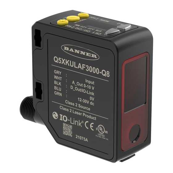
Product Description
Laser sensor with an analog output and IO-Link
This guide is designed to help you set up and install the Q5X Laser Triangulation Sensor. For complete information on programming, perfor-
mance, troubleshooting, dimensions, and accessories, please refer to the Instruction Manual at www.bannerengineering.com. Search for p/
n 219602 to view the Instruction Manual. Use of this document assumes familiarity with pertinent industry standards and practices.
WARNING:
•
Do not use this device for personnel protection
•
Using this device for personnel protection could result in serious injury or death.
•
This device does not include the self-checking redundant circuitry necessary to allow its use in personnel safe-
ty applications. A device failure or malfunction can cause either an energized (on) or de-energized (off) output
condition.
Features
The Q5X Laser Triangulation Sensor has three major features.
Q5X Features
2
1
Display and Indicators
The display is a four-digit, seven-segment LED. Run mode is the primary view displayed.
For 1-PT, 2-PT, BGS, FGS, and DYN TEACH modes, the display shows the current distance to the target in centimeters. For Dual TEACH
mode, the display shows the percentage matched to the taught reference surface. A display value of 999P indicates the sensor has not been
taught.
Display in Run Mode
1
STB 2-PT 1-PT MM
Output Indicators
•
Ch1: On when the displayed distance is within the taught
analog output window
•
Ch2: On when the displayed distance is within the taught
discrete output window
Stability Indicator (STB)
•
On—Stable signal within the specified sensing range
•
Flashing—Marginal signal, the target is outside the limits of
the specified sensing range, or a multiple peak condition
exists
•
Off—No target detected within the specified sensing range
Original Instructions
June 14, 2023
3
1.
Two output indicators (amber)
2.
Display
3.
Buttons
2
© Banner Engineering Corp.
1.
Stability Indicator (STB—Green)
2.
Active TEACH Indicators
◦
2-PT - Two-Point TEACH (Amber)
◦
1-PT - One-Point TEACH (Amber)
3.
Display value indicator (MM - Amber)
Active TEACH Indicators (2PT and 1PT)
•
2-PT on—Two-point TECH mode selected (default)
•
1-PT on—One-point TEACH mode selected
Display Value Indicator (MM)
•
On—Display shows the distance in millimeters (default)
•
Off—Display shows the analog output value
•
Toggle off the MM light by pressing SELECT when the sen-
sor is in run mode. This changes the display to show the
analog output value. Press SELECT again to show the dis-
tance value.
p/n: 219603 Rev. C
219603
Advertisement
Table of Contents

Subscribe to Our Youtube Channel
Related Manuals for Banner Q5X


Summary of Contents for Banner Q5X
- Page 1 Q5X Laser Triangulation Sensor with Analog Outputs and IO-Link Quick Start Guide Product Description Laser sensor with an analog output and IO-Link This guide is designed to help you set up and install the Q5X Laser Triangulation Sensor. For complete information on programming, perfor- mance, troubleshooting, dimensions, and accessories, please refer to the Instruction Manual at www.bannerengineering.com. Search for p/ n 219602 to view the Instruction Manual. Use of this document assumes familiarity with pertinent industry standards and practices. WARNING: • Do not use this device for personnel protection • Using this device for personnel protection could result in serious injury or death.
- Page 2 Q5X Laser Triangulation Sensor with Analog Outputs and IO-Link Quick Start Guide Buttons Use the sensor buttons (SELECT)(TEACH), (+)(CH1/CH2), and (-)(MODE) to program the sensor. Q5X sensor face (+)(CH1/CH2) (SELECT)(TEACH) • Press to navigate the sensor menu in Setup mode • Press to select menu items in Setup mode • Press to change setting values; press and hold to increase • Press and hold for longer than 2 seconds to start the cur- numeric values rently selected TEACH mode (the default is two-point •...
-
Page 3: Mount The Device
Q5X Laser Triangulation Sensor with Analog Outputs and IO-Link Quick Start Guide Class 2 Red Laser models: Reference IEC 60825-1:2014 Output: < 1.0 mW FDA (CDRH) warning label (Class 2) Laser wavelength: 640 to 670 nm LASER LIGHT DO NOT STARE INTO BEAM CLASS 2 LASER PRODUCT IEC 60825-1:2014. Wavelength 640-670nm; 1.0mW max. Complies with 21 CFR 1040.10 and 1040.11 except for... -
Page 4: Wiring Diagrams
Button Map from RSD1 to Sensor The sensor may be optionally connected to the Banner RSD1 remote display accessory. Refer to this table for the RSD1 button association with your sensor. Button association between the RSD1 and the Q4X/Q5X sensors Device ... - Page 5 Q5X Laser Triangulation Sensor with Analog Outputs and IO-Link Quick Start Guide Sensor Menu Map—Channel 1 June 14, 2023 page 5 © Banner Engineering Corp.
- Page 6 Q5X Laser Triangulation Sensor with Analog Outputs and IO-Link Quick Start Guide Sensor Menu Map—Channel 2 Basic TEACH Instructions Use the following instructions to teach the Q5X sensor. The instructions provided on the sensor display vary depending on the type of TEACH mode selected. Two-point TEACH is the default TEACH mode. page 6 June 14, 2023 © Banner Engineering Corp.
-
Page 7: Manual Adjustments
Q5X Laser Triangulation Sensor with Analog Outputs and IO-Link Quick Start Guide Press and hold TEACH for longer than 2 seconds to start the selected TEACH mode. Present the target. Press TEACH to teach the target. The target is taught and the sensor waits for the second target, if required by the selected TEACH mode, or returns to Run mode. Complete these steps only if it is required for the selected TEACH mode. Present the second target. Press TEACH to teach the target. The target is taught and the sensor returns to Run mode. See the Instruction Manual for detailed instructions and other available TEACH modes. The TEACH modes include: • Two-point analog teach 2-Pt —Sets the distance values associated with 0V and 10V (4mA and 20mA) based on taught target dis- tances • One point analog teach 1-Pt —Sets the 5V (12mA) midpoint of the analog output to center the analog output around a reference tar- get position ... -
Page 8: Specifications
Q5X Laser Triangulation Sensor with Analog Outputs and IO-Link Quick Start Guide To enter Loc mode, hold + and press - four times. To enter 0Loc mode, hold + and press - seven times. Holding + and pressing - four times unlocks the sensor from either lock mode and the sensor displays uLoc. Averaging Use the Averaging AUG menu to set the number of measurements that are averaged together for the analog output. Increasing the averaging improves repeatability, but increases the total response speed. The default is 16. The filter can be set to 1, 2, 4, 8, 16, 32, 64, 128, 256, or 512. Use the table to determine the total response speed. Response Speed (ms) Filter Setting Base Measurement Rate 1 2 4 8 16 32 64 128 256 512 0.5 ms 0.5 1.5 3 ... - Page 9 Q5X Laser Triangulation Sensor with Analog Outputs and IO-Link Quick Start Guide Remote Input Application Note Allowable Input Voltage Range: 0 to Vsupply For optimum performance, allow 10 minutes for the sensor to warm up Active High (internal weak pull-down): High state > (Vsupply – 2.25 V) at 2 mA maximum Environmental Rating ...
- Page 10 Q5X Laser Triangulation Sensor with Analog Outputs and IO-Link Quick Start Guide Continued from page 9 Required Overcurrent Protection Supply Supply Required Overcurrent Required Overcurrent Wiring Wiring Protection (A) Protection (A) WARNING: Electrical connections must (AWG) (AWG) be made by qualified personnel in ac- cordance with local and national electri- cal codes and regulations. ...
-
Page 11: Dual Mode Reference Surface Considerations
Banner Engineering Corp. warrants its products to be free from defects in material and workmanship for one year following the date of ship- ment. Banner Engineering Corp. will repair or replace, free of charge, any product of its manufacture which, at the time it is returned to the factory, is found to have been defective during the warranty period. This warranty does not cover damage or liability for misuse, abuse, or the improper application or installation of the Banner product. ... -
Page 12: Fcc Part 15 Class A
Q5X Laser Triangulation Sensor with Analog Outputs and IO-Link Quick Start Guide FCC Part 15 Class A This equipment has been tested and found to comply with the limits for a Class A digital device, pursuant to part 15 of the FCC Rules. These limits are designed to provide reasonable protection against harmful interference when the equipment is operated in a commercial environ-...
Need help?
Do you have a question about the Q5X and is the answer not in the manual?
Questions and answers