Banner Q45 Setup Manual
Occupancy solution kit: total count (tc)
Hide thumbs
Also See for Q45:
- Quick start manual (2 pages) ,
- Quick start manual (5 pages) ,
- Quick start manual (2 pages)
Advertisement
Quick Links
Advertisement

Subscribe to Our Youtube Channel
Related Manuals for Banner Q45


Summary of Contents for Banner Q45
- Page 1 Setup Guide 217889 Rev A...
-
Page 2: Kit Contents
Kit Contents Q45 Sensor Pair Reflector Pair includes AA batteries pre-mounted on bracket TL70 Wireless Indicator includes bracket and power supply Not Shown – mounted inside building Tools Needed Tape measure Phillips screwdriver DXM Controller Direct Select Operator Interface Power Supply... -
Page 3: How It Works
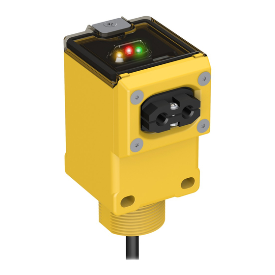
2 AM Central Time. Total Count (TC) Solution Kits are configured to monitor between one and four doors out of the box. The Q45 Sensor Pairs monitor people entering and exiting the area, for up to four doors, and give a total count of people inside. The Operator Interface displays the number of people in the area and allow for employee adjustments to the occupancy count. - Page 4 Supply Power to the Q45 Sensor Pair The Q45 Sensor Pair comes with two sensors: Sensor A and Sensor B. Sensor A has a metal connector on the bottom. Sensor B has a six-inch cable. Complete steps 1 through 6 below for both Sensor A and Sensor B.
- Page 5 Contact your local distributor or Banner Engineering’s Technical Support team at 1-800-203-5616 for more options or refer to our Troubleshooting section on page When mounting the Q45 Sensor Pairs on the inside of the door:...
- Page 6 Mounting II is possible when no other mounting options are available. Avoid mounting the sensors in areas where people will stand and block the sensors. Banner recommends using accessory mounting stands if a rigid mounting surface is not available. L-type Doors...
- Page 7 Reflector B. Rotate Sensor A outward until it is seeing Reflector A. If the sensors will not optically align to their reflector, refer to the Troubleshooting section for more information or contact your local distributor or Banner Engineering for assistance.
- Page 8 Define Your Alert Levels Set Up the Warning and Alarm Settings Using the DXM Controller Display This Occupancy Solution Kit is designed to provide visual indication of capacity levels for monitored areas. The Occupancy Limit indicates that the area has exceeded the capacity for people. The indicator light alerts people attempting to enter that they need to wait until people have left the area before entering.
-
Page 9: Troubleshooting
DXM Controller or TL70 Wireless Indicator Light to improve communication. The LED should flash green when the Indicator Light is communicating to the DXM Controller. If the indicator LEDs do not begin to flash green, contact your local distributor or Banner Engineering’s technical support team at 1-800-203-5616. - Page 10 Optional: Cloud Connectivity Banner Engineering’s Occupancy Solution Kit offers a fast and easy way to gain access to the data and history of the occupancy at your facility. The following section will show you how to configure your gateway over Ethernet and quickly create your solution on the Banner CDS platform.
- Page 11 Dashboard layouts and metrics for the solution. Click (Create). The Banner CDS application creates a site for the system and begins searching for a data push from the DXM Controller. The Occupancy Solution Kit is designed to push data once every five minutes to the Cloud.
-
Page 12: Optional Accessories
View Dashboard and Set Parameters Go to Dashboard After Banner CDS has created the site and detected the DXM Controller, click on (Go to Dashboard). The (Dashboard) panel appears and indicates the metrics of the Occupancy Solution Kit. The data on this dashboard will include a historical indication of the Occupancy of the area and a means of updating the Occupancy Limit and Occupancy Warning parameters.
Need help?
Do you have a question about the Q45 and is the answer not in the manual?
Questions and answers