
Subscribe to Our Youtube Channel
Related Manuals for Safran LRF 7047


Summary of Contents for Safran LRF 7047
- Page 1 LRF 7047- Integrator Manual INTEGRATOR MANUAL LRF 7047 914929_TML_LRF7047_en_Version B Public: 04.2019 Page: 1/72 Confidential & Proprietary Safran Vectronix AG – All rights reserved...
-
Page 2: Safety Notices
Skin Hazard distance: 0.3 m (10 s) WARNING LRF 7047 is exclusively designed for use in OEM products. Use of controls or adjustments or execution of procedures other than those specified herein may result in hazardous laser light exposure. Do not open or modify any parts of the LRF module or attempt your own repairs. Do not manipulate or adjust the performance of the LRF module. - Page 3 The packaging foam is made out of PE-LD-E-X. Dispose it according to your local regulations. 914929_TML_LRF7047_en_Version B Public: 04.2019 Confidential & Proprietary Safran Vectronix AG – All rights reserved Page: 3/72...
- Page 4 (vibration, shock, drop etc.), and before carrying out any important measurement tasks. Note the factors affecting measurement accuracy as described in chapter 2.3. Ranging Conditions. 914929_TML_LRF7047_en_Version B Public: 04.2019 Confidential & Proprietary Safran Vectronix AG – All rights reserved Page: 4/72...
-
Page 5: Disclaimer
Publication: The descriptions, specifications, design and procedures contained in this manual were effective at the time of publication of this manual. Safran Vectronix AG reserves the right to modify any of the above at any time without notice and without incurring obligations. -
Page 6: Table Of Contents
Unpacking ........................... 14 First steps with the LRF 7047 ..................... 15 Installation of Safran Vectronix Terminal Software ..............16 Use of LRF module with Safran Vectronix Terminal Software ........... 18 First steps without LRF Interface Kit ................... 20 Integration ............................21 Handling ............................ - Page 7 Reference design for Transmitter and receiver lenses ............... 68 Reference design for connector ....................69 UTF-8 ASCII Table ........................70 Abbreviations ..........................71 914929_TML_LRF7047_en_Version B Public: 04.2019 Confidential & Proprietary Safran Vectronix AG – All rights reserved Page: 7/72...
- Page 8 04.2019 / LLDA 9.1- 9.5 Reference designs 5.1 – 5.8 HW: Rephrase information, specification 6.1 - 6.7 SW SW: Operating mode, rephrase information 914929_TML_LRF7047_en_Version B Public: 04.2019 Confidential & Proprietary Safran Vectronix AG – All rights reserved Page: 8/72...
-
Page 9: General
LRF 7047- Integrator Manual 1 General The LRF 7047 (Part number 913906) is a powerful rangefinder module combining unsurpassed range performance with outstanding robustness and a coaxial 830 nm pointer. Target Group These operating instructions are aimed at integrators. To understand these instructions expert knowledge and skills are required. -
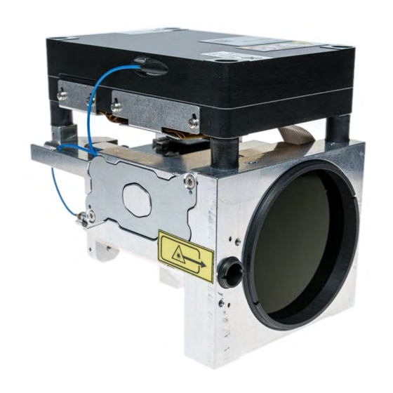
Page 10: Main Parts Of The Lrf Module
Stable aluminum bench including optics. Figure 1: LRF 7047 main parts (front view) Figure 2: LRF 7047 main parts (rear view) 914929_TML_LRF7047_en_Version B Public: 04.2019 Confidential & Proprietary Safran Vectronix AG – All rights reserved Page: 10/72... -
Page 11: Interface Parts
The following Figure 4 illustrates the sampled signal of the receiver diode. This information is used to calculate the distance. Figure 4: Pulsed Diode – sampled signal at the receiver diode 914929_TML_LRF7047_en_Version B Public: 04.2019 Confidential & Proprietary Safran Vectronix AG – All rights reserved Page: 11/72... -
Page 12: Electronics
LRF 7047- Integrator Manual 2.2 Electronics Safran Vectronix AG range finding technology is based on fiber lasers in combination with a multi-pulse measurement system. This allows pulses with low energy compared to a single high energy pulse. 2.3 Ranging Conditions In general two kinds of ranging conditions are described: Range capability: The possible laser range performance on a beam filling target. - Page 13 Firmly mounted modules allow a longer range, e.g. on tripod. Figure 6: Laser beam (0.5 mrad) on target (2’000 m) with kinetic tremor 914929_TML_LRF7047_en_Version B Public: 04.2019 Confidential & Proprietary Safran Vectronix AG – All rights reserved Page: 13/72...
-
Page 14: Getting Started
The packaging consists of a cardboard box and PE-LD-E-X packaging foam. Dispose it according to your local regulations. 914929_TML_LRF7047_en_Version B Public: 04.2019 Confidential & Proprietary Safran Vectronix AG – All rights reserved Page: 14/72... -
Page 15: First Steps With The Lrf 7047
Samtec System connector of the LRF. The USB connector is connected to a USB port of the PC. To run the LRF 7047, power (8-42 V) has to be provided via the red (+ pole) and black (- pole) pin plugs. The pointer interlock switch is protected by the red cap. -
Page 16: Installation Of Safran Vectronix Terminal Software
5) Choose the folder in which to install the software, either accepting the default option or browsing for a folder. Click “Install” to continue. 6) Click “Finish” to complete the setup program. 914929_TML_LRF7047_en_Version B Public: 04.2019 Confidential & Proprietary Safran Vectronix AG – All rights reserved Page: 16/72... - Page 17 7) Read and either accept or decline the terms of use. If declined, the program will abort. 8) If the terms of use are accepted, the demonstration program will load. 914929_TML_LRF7047_en_Version B Public: 04.2019 Confidential & Proprietary Safran Vectronix AG – All rights reserved Page: 17/72...
-
Page 18: Use Of Lrf Module With Safran Vectronix Terminal Software
3) Either set the settings manually and press OK or select “Search for LRF Module…”. (Please note: values above are for illustration only and may differ to your modules requirements) 914929_TML_LRF7047_en_Version B Public: 04.2019 Confidential & Proprietary Safran Vectronix AG – All rights reserved Page: 18/72... - Page 19 Make sure you have selected the right module in stage 1 8) The response from the LRF will be shown in the dialog box. 914929_TML_LRF7047_en_Version B Public: 04.2019 Confidential & Proprietary Safran Vectronix AG – All rights reserved Page: 19/72...
-
Page 20: First Steps Without Lrf Interface Kit
3.5 First steps without LRF Interface Kit LRF modules can be connected to your PC without an interface cable provided by Safran Vectronix. In this case we recommend reading this manual carefully before using the LRF module. Please be aware of the risk of wrong pin-connection or destroying the module by applying overvoltage and other errors. -
Page 21: Integration
LRF module (see chapter 4.6). 4.2 Design recommendations The mechanical interface drawing of LRF 7047 can be found in the appendix (chapter 9.2). The mechanical interface drawing is applicable for LRF 7047 (Article number 913906) 4.3 Preparation... -
Page 22: Mounting
Vibration and shock outside the specified values can destroy or shift parts inside the LRF in a way that renders the LRF unusable. 914929_TML_LRF7047_en_Version B Public: 04.2019 Confidential & Proprietary Safran Vectronix AG – All rights reserved Page: 22/72... -
Page 23: Mounting The Lrf Module With Detached Laserbox
4.4.1 Mounting the LRF module with detached Laserbox In order to mount and operate the LRF 7047 with a detached Laserbox follow the steps below: 1. The LRF module must be unplugged 2. Loosen both screws (A) with a T5 screwdriver and remove the flexcable protective cover 3. -
Page 24: Boresighting
4.5 Boresighting The module receiver and transmitter are boresighted in the factory. For this reason, the module can be mounted and replaced easily. LRF 7047 offers two wavelengths for boresighting. 4.5.1 Boresighting at 1550 nm For a professional boresighting of the LRF module with the main optical axis of the host system, we recommend the use of a collimator and a camera sensitive to the 1’550 nm wavelength of the laser... -
Page 25: Boresighting At 830 Nm
However, this only works when the card is quite close to the LRF module. To see the laser beam of LRF 7047 modules, the laser viewing card must absorb light of 1550 nm wavelength (or 830 nm if the optional pointer is available). -
Page 26: Nitrogen Flushing
The yellow pieces of tape stop dust penetrating the optical system and shall be removed just before the host system is sealed and purged. 914929_TML_LRF7047_en_Version B Public: 04.2019 Confidential & Proprietary Safran Vectronix AG – All rights reserved Page: 26/72... -
Page 27: Front Protection
For optical isolation, the use of EPDM L 7510 material with shore hardness 50 +/-5 Shore A is recommended. 914929_TML_LRF7047_en_Version B Public: 04.2019 Confidential & Proprietary Safran Vectronix AG – All rights reserved Page: 27/72... - Page 28 The tilt angle influences LRF range performance, being 0° angle the optimal value. NOTICE The tilt angle prevents the pointer from creating ghost images. 914929_TML_LRF7047_en_Version B Public: 04.2019 Confidential & Proprietary Safran Vectronix AG – All rights reserved Page: 28/72...
-
Page 29: Eye Safety
Implementation of laser safety measures is the system integrator’s responsibility. The LRF 7047 provides a hardware interlock function to ensure that the pointer is not switched- on unintentionally. To emit a non-eye safe laser beam, the LRF 7047 has to be powered correctly, woken-up, the interlock pins need to be short-circuited and the pointer software command has to be sent via the serial interface. -
Page 30: Eye Safety Kit
4.9 Deflection area of Double Stage Fiber Laser NOTICE The double stable fiber laser of LRF 7047 is equipped with shock absorbing elements to withstand pyro shock impacts up to 800 g. These shock impacts can cause a deflection of the double stage fiber laser of 5 mm in X, Y and Z direction. -
Page 31: Hw Interface
9.1 System connector reference design. Figure 20: Position of Samtec System connector Figure 21: Location of Pin # 1, 2, 39, 40 914929_TML_LRF7047_en_Version B Public: 04.2019 Confidential & Proprietary Safran Vectronix AG – All rights reserved Page: 31/72... -
Page 32: Pin Descriptions
// leave open Interlock_1 do not connect // leave open Interlock_2 do not connect // leave open Interlock_3 do not connect // leave open Interlock_4 914929_TML_LRF7047_en_Version B Public: 04.2019 Confidential & Proprietary Safran Vectronix AG – All rights reserved Page: 32/72... -
Page 33: Esd Protection
+1kV Charged-device model (CDM) 5.4 Operating Conditions Parameter Typical Unit Operating Voltage PWR_IN Operating Voltage PWR_SAFE 5.25 Typical values are recommended for operation. 914929_TML_LRF7047_en_Version B Public: 04.2019 Confidential & Proprietary Safran Vectronix AG – All rights reserved Page: 33/72... -
Page 34: Absolute Maximum Ratings
The following graphs intention is to serve as a reference and not as specification. 914929_TML_LRF7047_en_Version B Public: 04.2019 Confidential & Proprietary Safran Vectronix AG – All rights reserved Page: 34/72... -
Page 35: Current Consumption Detail: " Powering Up
Typical response of the sensor if powered under typical conditions (12 V; T = 25°C; Laboratory power source) Figure 23: Typical current peak during measuring sequence 914929_TML_LRF7047_en_Version B Public: 04.2019 Confidential & Proprietary Safran Vectronix AG – All rights reserved Page: 35/72... -
Page 36: Serial Interface
The LRF System has to be connected to the host system ground via the three screws and the area around the three screws. The LRF bench is conductive. 914929_TML_LRF7047_en_Version B Public: 04.2019 Confidential & Proprietary Safran Vectronix AG – All rights reserved Page: 36/72... -
Page 37: Pwr_Safe Signal Pin#9
From the “Normal operating Mode”, the module can reach the “OFF Mode” using the corresponding command, see 6.5.6 Operating mode selection (to “OFF Mode”). Figure 25: PWR_SAFE signal and awaking commands 914929_TML_LRF7047_en_Version B Public: 04.2019 Confidential & Proprietary Safran Vectronix AG – All rights reserved Page: 37/72... -
Page 38: Sw Interface
6.5.3, 6.5.7 and 6.5.8) the LRF module will ignore any incoming characters. 914929_TML_LRF7047_en_Version B Public: 04.2019 Confidential & Proprietary Safran Vectronix AG – All rights reserved Page: 38/72... -
Page 39: Command Structure
String: A couple of characters without ending with \0. Within the string, only the characters 32 (0x20) ... 126 (0x7E) except 0x2A (‘*’), 0x2C (‘,’), 0x3C (‘<’), 0x21 (‘!’) and 0x3E (‘>’) are allowed. 914929_TML_LRF7047_en_Version B Public: 04.2019 Confidential & Proprietary Safran Vectronix AG – All rights reserved Page: 39/72... - Page 40 Serial interface Rx overflow error others Table 2: Not acknowledge error list Example for an invalid parameter error: >LM,Md,3,0*31<0D> >NA,2*ED<0D> Example for a checksum error: >LM,Md,3*D6<0D> >NA,0*EB<0D> 914929_TML_LRF7047_en_Version B Public: 04.2019 Confidential & Proprietary Safran Vectronix AG – All rights reserved Page: 40/72...
-
Page 41: Timing / Power On
1 second, in order to comply with eye safety limitations. This timing is dependent on range conditions. Range commands for continuous and block request already watch out the eye safety buffer. 914929_TML_LRF7047_en_Version B Public: 04.2019 Confidential & Proprietary Safran Vectronix AG – All rights reserved Page: 41/72... -
Page 42: Operational Commands
Example of a successful range request command transaction: Host LRF Module Command frame: >LM,Md,3*D5<0D> LRF Module Host Acknowledge frame: >AC*84<0D> Response frame: >LM,Md,v0006091,R000E301,R000E301*46<0D> Prompt: < 914929_TML_LRF7047_en_Version B Public: 04.2019 Confidential & Proprietary Safran Vectronix AG – All rights reserved Page: 42/72... -
Page 43: Fake Range Request >Lm,Mf,X*
Example of a successful Fake Range Request command transaction: Host LRF Module Command frame: >LM,Mf,3*D7<0D> LRF Module Host Acknowledge frame: >AC*84<0D> Response frame: >LM,Mf,v0123400,v0432100,R000E301*57<0D> Prompt: < 914929_TML_LRF7047_en_Version B Public: 04.2019 Confidential & Proprietary Safran Vectronix AG – All rights reserved Page: 43/72... -
Page 44: Laser Continuous Low Power Mode >Lm,Tl,X*
Alignment is performed by the operator. Afterwards, the emission shall be deactivated. Host LRF Module Command frame: >LM,Tl,0*E1<0D> LRF Module Host Acknowledge frame: >AC*84<0D> Prompt: < 914929_TML_LRF7047_en_Version B Public: 04.2019 Confidential & Proprietary Safran Vectronix AG – All rights reserved Page: 44/72... -
Page 45: Laser Pointer Command >Lm,Rp,X*
It is recommended to operate the pointer: At extreme temperatures (below -10°C or above 45°C) for 15 sec. At room temperature (25°C) for 4 minutes. 914929_TML_LRF7047_en_Version B Public: 04.2019 Confidential & Proprietary Safran Vectronix AG – All rights reserved Page: 45/72... -
Page 46: Laser Pointer Arm Command >Lm,Lp,X*
Host LRF Module Command frame: >LM,Lp,0*DD<0D> LRF Module Host Acknowledge frame: >AC*84<0D> Prompt: < Host LRF Module Hardware Interlock pins are released. 914929_TML_LRF7047_en_Version B Public: 04.2019 Confidential & Proprietary Safran Vectronix AG – All rights reserved Page: 46/72... -
Page 47: Operating Mode Selection >Lm,Op,X*
Example of an Operating mode selection command transaction: Host LRF Module Command frame: >LM,Op,1*E1<0D> LRF Module Host Acknowledge frame: >AC*84<0D> Prompt: < 914929_TML_LRF7047_en_Version B Public: 04.2019 Confidential & Proprietary Safran Vectronix AG – All rights reserved Page: 47/72... -
Page 48: Block Range Request >Lm,Mb,X*
Example of a successful Block Range Request command transaction: Host LRF Module Command frame: >LM,Mb,2*D2<0D> LRF Module Host Acknowledge frame: >AC*84<0D> Response frame: >LM,Mb,v0004280,R000E301,R000E301*42<0D> >LM,Mb,v0004280,R000E301,R000E301*42<0D> Prompt: < 914929_TML_LRF7047_en_Version B Public: 04.2019 Confidential & Proprietary Safran Vectronix AG – All rights reserved Page: 48/72... -
Page 49: Continuous Range Request >Lm,Mt,X*
LRF Module Host Acknowledge frame: >AC*84<0D> Response frame: >LM,Mt,v0006404,v0090656,v0077726,t018692980*1C<0D> >LM,Mt,v0006406,v0090981,v0087450,t018758928*1F<0D> >LM,Mt,v0072447,v0085329,v0074191,t018862206*16<0D> >… Host LRF Module Command frame: >LM,Mt,0*E2<0D> Acknowledge frame: >AC*84<0D> Prompt: < 914929_TML_LRF7047_en_Version B Public: 04.2019 Confidential & Proprietary Safran Vectronix AG – All rights reserved Page: 49/72... -
Page 50: Error Codes
Target detected inside Range Gate ‘T’: Module (LRF) is operating outside of the temperature specification. T0505950 The accuracy is not guaranteed. Table 11: Error Codes 914929_TML_LRF7047_en_Version B Public: 04.2019 Confidential & Proprietary Safran Vectronix AG – All rights reserved Page: 50/72... -
Page 51: Servicing Commands
Host LRF Module Command frame: >LM,Br,4*D9<0D> LRF Module Host Acknowledge frame: >AC*84<0D> Prompt** < After restart, at the new baud rate. 914929_TML_LRF7047_en_Version B Public: 04.2019 Confidential & Proprietary Safran Vectronix AG – All rights reserved Page: 51/72... -
Page 52: Version, Software And Module Type Request >Lm,Iv*
> LM,Iv,Prod. Type: LRF 7047 ,MCU Firmw.: 01.00.00.B6 Date: Jul 20 2017,MCU Booter: 01.00,DSP Firmw.: 00.01 Date: Jun 14 2017,Hardware: 01-01-00-00-31,Options: PF,S/N.: 00000,Art.: 913906*FE<0D> Prompt: < 914929_TML_LRF7047_en_Version B Public: 04.2019 Confidential & Proprietary Safran Vectronix AG – All rights reserved Page: 52/72... -
Page 53: Set Range Gate Min >Lm,Gl,X*
Example of a set range gate min command transaction: Host LRF Module Command frame: >LM,Gl,500*39<0D> LRF Module Host Acknowledge frame: >AC*84<0D> Prompt: < 914929_TML_LRF7047_en_Version B Public: 04.2019 Confidential & Proprietary Safran Vectronix AG – All rights reserved Page: 53/72... -
Page 54: Set Range Gate Max >Lm,Gh,X*
->1634.20 m 100 m target: Outside range gate. ->473.80 m v0047380 R000E302 Table 17: Example of range output for a range gate min 914929_TML_LRF7047_en_Version B Public: 04.2019 Confidential & Proprietary Safran Vectronix AG – All rights reserved Page: 54/72... -
Page 55: Get Current Range Gate Settings >Lm,Ig,X*
Example of a get range gate (min) settings command transaction: Host LRF Module Command frame: >LM,Ig,1*D2<0D> LRF Module Host Acknowledge frame: >AC*84<0D> Response frame: >LM,Ig,00000*91<0D> Prompt: < 914929_TML_LRF7047_en_Version B Public: 04.2019 Confidential & Proprietary Safran Vectronix AG – All rights reserved Page: 55/72... -
Page 56: Reset Lrf Module To Default Settings >Lm,Rd*
Example of a reset LRF module to default settings command transaction: Host LRF Module Command frame: >LM,Rd*7B<0D> LRF Module Host Acknowledge frame: >AC*84<0D> Prompt: < 914929_TML_LRF7047_en_Version B Public: 04.2019 Confidential & Proprietary Safran Vectronix AG – All rights reserved Page: 56/72... -
Page 57: Timestamp Activation >Lm,At,X*
Example of a timestamp activation command transaction: Host LRF Module Command frame: >LM,At,1*D7<0D> LRF Module Host Acknowledge frame: >AC*84<0D> Prompt: < 914929_TML_LRF7047_en_Version B Public: 04.2019 Confidential & Proprietary Safran Vectronix AG – All rights reserved Page: 57/72... -
Page 58: Get Time Stamp >Lm,It*
Example of a get timestamp command transaction: Host LRF Module Command frame: >LM,It*82<0D> LRF Module Host Acknowledge frame: >AC*84<0D> Response frames: >LM,It,t743721867*FF<0D> Prompt: < 914929_TML_LRF7047_en_Version B Public: 04.2019 Confidential & Proprietary Safran Vectronix AG – All rights reserved Page: 58/72... -
Page 59: Range Commands With Activated Timestamp
Example of a distance measurement (Md command) with activated time stamp (with parameter 2): Host LRF Module Command frame: >LM,Md,3*D5<0D> LRF Module Host Acknowledge frame: >AC*84<0D> Response frames: >LM,Md, v0027091,R000E301,R000E301,t006295701,t006683761*4C<0D> Prompt: < 914929_TML_LRF7047_en_Version B Public: 04.2019 Confidential & Proprietary Safran Vectronix AG – All rights reserved Page: 59/72... -
Page 60: Test Commands
Example of an IBIT command transaction: Host LRF Module Command frame: >LM,Tb,1*D8<0D> LRF Module Host Acknowledge frame: >AC*84<0D> Response frame: >LM,Tb,IBIT,T+29.75,FF*37<0D> Prompt: < 914929_TML_LRF7047_en_Version B Public: 04.2019 Confidential & Proprietary Safran Vectronix AG – All rights reserved Page: 60/72... -
Page 61: Pbit (Power Built-In Test) >Lm,Tb,2*
Example of a PBIT command transaction: Host LRF Module Command frame: >LM,Tb,2*D9<0D> LRF Module Host Acknowledge frame: >AC*84<0D> Response frame: >LM,Tb,PBIT,FE,FE*44<0D> Prompt: < 914929_TML_LRF7047_en_Version B Public: 04.2019 Confidential & Proprietary Safran Vectronix AG – All rights reserved Page: 61/72... -
Page 62: Maintenance
Level 4: Factory Repair In case of a defect, the module has to be returned to the Safran Vectronix AG Customer Service Center, where diagnosis and repair or replacement, depending on cost to repair will be done. Please visit our Service Website http://www.safran-vectronix.com/service/... -
Page 63: Lrf Interface Tools
8.1 LRF Interface Kit Safran Vectronix AG can assist the integration of the LRF 7047 by supplying an LRF Interface Kit (part number 914752). The aim of the LRF Interface Kit is to enable connection and powering the LRF 7047 before integration begins and to increase personnel safety. -
Page 64: Appendix
The following drawing indicates the design requirements for the host system connector which needs to be attached to the system connector of the LRF module. All information can also be found here: http://suddendocs.samtec.com/prints/hlcd%20applications-mkt.pdf 914929_TML_LRF7047_en_Version B Public: 04.2019 Confidential & Proprietary Safran Vectronix AG – All rights reserved Page: 64/72... - Page 65 LRF 7047- Integrator Manual 914929_TML_LRF7047_en_Version B Public: 04.2019 Confidential & Proprietary Safran Vectronix AG – All rights reserved Page: 65/72...
-
Page 66: Mechanical Interface Drawing
LRF 7047- Integrator Manual 9.2 Mechanical Interface Drawing 914929_TML_LRF7047_en_Version B Public: 04.2019 Confidential & Proprietary Safran Vectronix AG – All rights reserved Page: 66/72... - Page 67 LRF 7047- Integrator Manual 914929_TML_LRF7047_en_Version B Public: 04.2019 Confidential & Proprietary Safran Vectronix AG – All rights reserved Page: 67/72...
-
Page 68: Reference Design For Transmitter And Receiver Lenses
LRF 7047- Integrator Manual 9.3 Reference design for Transmitter and receiver lenses 914929_TML_LRF7047_en_Version B Public: 04.2019 Confidential & Proprietary Safran Vectronix AG – All rights reserved Page: 68/72... -
Page 69: Reference Design For Connector
LRF 7047- Integrator Manual 9.4 Reference design for connector 914929_TML_LRF7047_en_Version B Public: 04.2019 Confidential & Proprietary Safran Vectronix AG – All rights reserved Page: 69/72... -
Page 70: Utf-8 Ascii Table
LRF 7047- Integrator Manual 9.5 UTF-8 ASCII Table 914929_TML_LRF7047_en_Version B Public: 04.2019 Confidential & Proprietary Safran Vectronix AG – All rights reserved Page: 70/72... -
Page 71: Abbreviations
Identical with <CR> Original Equipment Manufacturer Personal Computer PBIT Power Built-In Test Power Receiver Start of Message Software SWIR Shortwave Infrared Sender Universal Serial Bus 914929_TML_LRF7047_en_Version B Public: 04.2019 Confidential & Proprietary Safran Vectronix AG – All rights reserved Page: 71/72... - Page 72 LRF 7047- Integrator Manual 914929_TML_LRF7047_en_Version B Public: 04.2019 Confidential & Proprietary Safran Vectronix AG – All rights reserved Page: 72/72...
Need help?
Do you have a question about the LRF 7047 and is the answer not in the manual?
Questions and answers