
Related Manuals for Safran LRF 3013


Summary of Contents for Safran LRF 3013
- Page 1 Integrator Manual LRF 3013 Document number: TML 913655 ver A Public: 13.03.2017 Confidential & Proprietary Safran Vectronix AG – All rights reserved page: 1/36...
-
Page 2: Disclaimer
The descriptions, specifications, design and procedures contained in this manual were effective at the time of publication of this manual. Safran Vectronix AG reserves the right to modify any of the above at any time without notice and without incurring obligations. -
Page 3: Safety Notices
For safe use of the LRF module, please note the safety instructions in this Integrator Manual. LRF 3013 is exclusively designed for use in OEM products. The LRF 3013 is designed and configured as a Class 1 Laser device. Use of controls or adjustments or performance of procedures other than those specified herein may result in hazardous laser light exposure. - Page 4 (vibration, shock, drop etc.), and before carrying out any important measurement tasks. Changes Revision Chapter Description New Demonstration Software, grammatical text revisions, document design Document number: TML 913655 ver A Public: 13.03.2017 Confidential & Proprietary Safran Vectronix AG – All rights reserved page: 4/36...
-
Page 5: Table Of Contents
Continuous distance measurement ..................27 6.2.3 Software versions, hardware configuration and serial number ..........28 6.2.4 Built-In Self Test ........................29 Document number: TML 913655 ver A Public: 13.03.2017 Confidential & Proprietary Safran Vectronix AG – All rights reserved page: 5/36... - Page 6 Service Levels ........................31 LRF Interface Kit .......................32 Appendix ...........................33 System Connector ........................33 Mechanical Interface Drawing ...................... 35 Document number: TML 913655 ver A Public: 13.03.2017 Confidential & Proprietary Safran Vectronix AG – All rights reserved page: 6/36...
-
Page 7: General
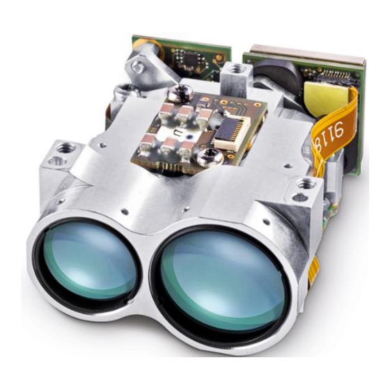
LRF 3013 Integrator Manual 1 General The LRF 3013 (Vectronix article number 913461) is the smallest and most lightweight member of Vectronix’ LRF Modules family. It combines unsurpassed range performance with outstanding robustness. The rangefinder module is class 1 eye-safe according to IEC 60825 and ANSI Z136.1 (2007). -
Page 8: Interface Parts
Figure 3 below indicates how laser pulses are emitted from the transmitter, reflected at the target and sampled by the receiver. Figure 3: Pulsed Diode – Laser Pulses Document number: TML 913655 ver A Public: 13.03.2017 Confidential & Proprietary Safran Vectronix AG – All rights reserved page: 8/36... -
Page 9: Electronics
A large target allows longer ranges because more of the laser light is returned to the LRF module. Document number: TML 913655 ver A Public: 13.03.2017 Confidential & Proprietary Safran Vectronix AG – All rights reserved page: 9/36... - Page 10 Laser beam NATO size (2.3x2.3 m) Figure 6.: Laser beam (1 mrad) on target (1’000 m) with kinetic tremor Document number: TML 913655 ver A Public: 13.03.2017 Confidential & Proprietary Safran Vectronix AG – All rights reserved page: 10/36...
-
Page 11: Getting Started
Choose the folder in which to install the software, either accepting the default option or browsing for a folder. Click “Install” to continue. Document number: TML 913655 ver A Public: 13.03.2017 Confidential & Proprietary Safran Vectronix AG – All rights reserved page: 11/36... - Page 12 Read and either accept or decline the terms of use. If declined, the program will abort. If the terms of use are accepted, the demonstration program will load. Document number: TML 913655 ver A Public: 13.03.2017 Confidential & Proprietary Safran Vectronix AG – All rights reserved page: 12/36...
- Page 13 3. Insert a fully charged 9 V battery into the Universal Interface or connect to it an external power supply. Safran Vectronix recommends the use of an external power supply of approx. 12V DC / 3 A. When battery operated, only a limited number of measurements are possible.
-
Page 14: Using The Safran Vectronix Terminal Software
After making sure that you have connected and powered up the interface, selected the right module, press “Start Search” Document number: TML 913655 ver A Public: 13.03.2017 Confidential & Proprietary Safran Vectronix AG – All rights reserved page: 14/36... - Page 15 The response from the LRF will be shown in the dialog box. Note: You can use the symbol to clear the log. Document number: TML 913655 ver A Public: 13.03.2017 Confidential & Proprietary Safran Vectronix AG – All rights reserved page: 15/36...
-
Page 16: First Steps Without Lrf Interface Kit
Power supply must not exceed the range of 4.5…16 V The default Baud rate for LRF 3013 modules is 57’600 Bd First range measurements can be performed by sending the software commands “>Md1<CR>” to the LRF module. To achieve a valid range result, aim at targets of at least 30 m distance and ensure that you hit the target and that no obstacles like closed windows are between the LRF and the target. -
Page 17: Integration
Remove stickers on bench holes only before flushing the air out of the system, so that nitrogen also fills the optical system of the LRF module. 4.2 Design recommendations The mechanical interface drawing of LRF 3013 can be found in the appendix (chapter 9.2). 4.2.1 Preparation The surface that the LRF module will be mounted on must be equally flat or preferable better than the surface represented by the LRF’s mounting pads. -
Page 18: Boresighting
1550 nm Collimator Camera Main optical axis Host System Figure 8: Alignment Set-up with collimator and 1550 nm camera Document number: TML 913655 ver A Public: 13.03.2017 Confidential & Proprietary Safran Vectronix AG – All rights reserved page: 18/36... -
Page 19: Nitrogen Flushing
However, this only works when the card is quite close to the LRF module. To see the laser beam of LRF 3013 modules, the laser viewing card must absorb light of 1550 nm wavelength. Vendors of such cards are: ... -
Page 20: Eye Safety
0° tilt angle. 4.4 Eye Safety LRF 3013 meets Class 1 eye safety requirements according to IEC 60825 and ANSI Z136.1. The eye safety of the host system has to be tested and guaranteed at the system level by the OEM system integrator. -
Page 21: Hw Interface
9.1. The connector position can be found in the mechanical interface drawing in the appendix chapter 9.2. Document number: TML 913655 ver A Public: 13.03.2017 Confidential & Proprietary Safran Vectronix AG – All rights reserved page: 21/36... -
Page 22: Power Supply & Timing
Figure 14 above shows the current consumption, UART signal and timing of a range measurement event. The diagram shows the following key figures: Document number: TML 913655 ver A Public: 13.03.2017 Confidential & Proprietary Safran Vectronix AG – All rights reserved page: 22/36... - Page 23 Figure 15: Start-up behaviour with 5 V power supply Figure 15 shows the current consumption behavior of LRF 3013 during start-up. The diagram shows a few current peaks of about 0.9 A and the maximum current peak of ca. 1.3 A. (Keep in mind that current...
-
Page 24: Serial Interface: Uart
The LRF System has to be connected to the host system ground via the three screws and the area around the three screws. The LRF bench is conductive. Document number: TML 913655 ver A Public: 13.03.2017 Confidential & Proprietary Safran Vectronix AG – All rights reserved page: 24/36... -
Page 25: Sw Interface
A comma, separating the two 0x2C parameters One or more See command description Second parameter digits (optional) <CR> End of command 0x0D Document number: TML 913655 ver A Public: 13.03.2017 Confidential & Proprietary Safran Vectronix AG – All rights reserved page: 25/36... -
Page 26: Ack And Nack
R000E301BB<CR> Second strongest return: no valid range (R & E301) R000E301BB<CR> Weakest return: no valid range (R & E301) Document number: TML 913655 ver A Public: 13.03.2017 Confidential & Proprietary Safran Vectronix AG – All rights reserved page: 26/36... -
Page 27: Continuous Distance Measurement
ASCII Value in Hex Sum in Hex 106h 13Bh 174h 1A9h 1D9h Checksum = 8 least significant bits of 1D9 = D9 Document number: TML 913655 ver A Public: 13.03.2017 Confidential & Proprietary Safran Vectronix AG – All rights reserved page: 27/36... -
Page 28: Software Versions, Hardware Configuration And Serial Number
“yy” : ‘Extension’ board “ww” : Transmitter board “zz” : Receiver board See PD3 for details about exact values. Document number: TML 913655 ver A Public: 13.03.2017 Confidential & Proprietary Safran Vectronix AG – All rights reserved page: 28/36... -
Page 29: Built-In Self Test
Characters sourced by the module are in green (hex BIST: F7<0D> values in red). < The hex value 0D is the carriage return. Document number: TML 913655 ver A Public: 13.03.2017 Confidential & Proprietary Safran Vectronix AG – All rights reserved page: 29/36... -
Page 30: Low-Power Continuous Lasing Mode
25ms. Then the LRF system is ready to receive a defined command. The power has to be applied at the PWR-IN (Pin 1-3) before. Document number: TML 913655 ver A Public: 13.03.2017 Confidential & Proprietary Safran Vectronix AG – All rights reserved page: 30/36... -
Page 31: Maintenance
In case of a defect, the module has to be returned to the Vectronix Customer Service Center. There, diagnosis and repair or replacement, depending on economic reasons will be done. Document number: TML 913655 ver A Public: 13.03.2017 Confidential & Proprietary Safran Vectronix AG – All rights reserved page: 31/36... -
Page 32: Lrf Interface Kit
Vectronix supports integrating LRF 3013 by supplying an LRF Interface Kit. The intention of the LRF Interface Kit is to facilitate wiring and powering LRF 3013 before starting. The LRF Interface Box, a standard terminal software and the LRF User Manual is enough to get a first impression of the LRF Module. -
Page 33: Appendix
0.05 to 0.1 µm - Nickel underplating (chemical) 2 to 3 µm ±0.05 0.5x (10-1) = 4.5 ±0.05 0.5x (10+1) = 5.5 Document number: TML 913655 ver A Public: 13.03.2017 Confidential & Proprietary Safran Vectronix AG – All rights reserved page: 33/36... - Page 34 LRF 3013 Integrator Manual Document number: TML 913655 ver A Public: 13.03.2017 Confidential & Proprietary Safran Vectronix AG – All rights reserved page: 34/36...
-
Page 35: Mechanical Interface Drawing
LRF 3013 Integrator Manual 9.2 Mechanical Interface Drawing Document number: TML 913655 ver A Public: 13.03.2017 Confidential & Proprietary Safran Vectronix AG – All rights reserved page: 35/36...
Need help?
Do you have a question about the LRF 3013 and is the answer not in the manual?
Questions and answers