Toshiba vlp technology P9 ASD Installation & Operation Manual
Hide thumbs
Also See for vlp technology P9 ASD:
- Installation and operation manual (287 pages) ,
- Quick start manual (105 pages)
Table of Contents
Advertisement
Quick Links
Advertisement
Chapters
Table of Contents

Related Manuals for Toshiba vlp technology P9 ASD


Summary of Contents for Toshiba vlp technology P9 ASD
- Page 1 October, 2014 P9 ASD & O NSTALLATION PERATION ANUAL...
- Page 2 P9 ASD Installation & Operation Manual DN: 64054-005 October, 2014...
- Page 3 Congratulations on the purchase of the new P9 Adjustable Speed Drive! The P9 Adjustable Speed Drive (ASD) is a solid-state AC drive that features Toshiba International Corporation’s (TIC) new Virtual Linear Pump function. The VLP algorithm was designed to remove the guess work that is associated with the setup of pumping systems.
- Page 4 The sales contract contains the entire obligation of Toshiba International Corporation. The warranty contained in the contract between the parties is the sole warranty of Toshiba International Corporation and any statements contained herein do not create new warranties or modify the existing warranty.
- Page 5 At Toshiba International Corporation we are continuously striving for better ways to meet the constantly changing needs of our customers. E-mail your comments, questions, or concerns about this publication to Technical-Publications-Dept@tic.toshiba.com.
- Page 6 P9 Adjustable Speed Drive Please complete the Warranty Card supplied with the P9 ASD and return it to Toshiba International Corporation by prepaid mail. This will activate the 12-month warranty from the date of installation; but, shall not exceed 18 months from the shipping date.
-
Page 7: Table Of Contents
Table of Contents General Safety Information ....................1 Safety Alert Symbol ......................1 Signal Words ........................1 Special Symbols .........................2 Equipment Warning Labels ....................2 Qualified Personnel ......................2 Equipment Inspection ......................3 Handling and Storage ......................3 Disposal ..........................3 Installation Precautions ......................4 Location and Ambient Requirements .................4 Mounting Requirements .....................4 Conductor Routing and Grounding Precautions ..............5 Power Connections Precautions ..................6... - Page 8 Connecting the ASD ......................16 Lead Length Specifications ....................20 I/O and Control .........................21 Electronic Operator Interface ....................28 EOI Operation ........................28 Battery Backup .........................28 Real-Time Clock Setting ....................29 EOI Remote Mounting .....................29 EOI Features ........................30 EOI Remote Mounting .....................33 System Operation ........................36 Initial Setup ........................36 Standard Startup Wizard Parameters ................36 Operation (Hand) ......................39...
-
Page 9: General Safety Information
General Safety Information DO NOT attempt to install, operate, maintain, or dispose of this equipment until you have read and understood all of the product safety information and directions that are contained in this manual. Safety Alert Symbol The Safety Alert Symbol is comprised of an equilateral triangle enclosing an exclamation mark. This indicates that a potential personal injury hazard exists. -
Page 10: Special Symbols
Special Symbols To identify special hazards, other symbols may appear in conjunction with the DANGER, WARNING, and CAUTION signal words. These symbols indicate areas that require special and/or strict adherence to the procedures to prevent serious injury to personnel or loss of life. Electrical Hazard Symbol A symbol that is comprised of an equilateral triangle enclosing a lightning bolt indicates a hazard of injury from electrical... -
Page 11: Equipment Inspection
Equipment Inspection • Upon receipt of the equipment, inspect the packaging and equipment for shipping damage. • Carefully unpack the equipment and check for parts that may have been damaged during shipping, missing parts, or concealed damage. If any discrepancies are discovered, it should be noted with the carrier prior to accepting the shipment, if possible. -
Page 12: Installation Precautions
Installation Precautions Location and Ambient Requirements • The TIC ASD is intended for permanent installations only. • Installation should conform to the National Electrical Code — Article 110 (NEC) (Requirements For Electrical Installations), all regulations of the Occupational Safety and Health Administration, and any other applicable national, regional, or industry codes and standards. -
Page 13: Conductor Routing And Grounding Precautions
Conductor Routing and Grounding Precautions WARNING • Use separate metal conduits for routing the input power, output power, and control circuits. • A separate ground cable should be run inside the conduit with the input power, output power, and control circuits. •... -
Page 14: Power Connections Precautions
Power Connections Precautions DANGER C O N T A C T W I T H E N E R G I Z E D W I R I N G W I L L C A U S E S E V E R E I N J U R Y O R L O S S O F L I F E . •... -
Page 15: System Integration Precautions
System Integration Precautions The following precautions are provided as general guidelines for the setup of the ASD within the system. • The TIC ASD is a general-purpose product. It is a system component only and the system design should take this into consideration. Please contact your TIC Sales Representative for application- specific information or for training support. -
Page 16: System Setup Requirements
System Setup Requirements • With the exception of the TBA Pump Number (F434), ensure that all Time-Based Alternation parameter settings and the real-time clock settings for each ASD within the system are the same. • When using the ASD as an integral part of a larger system, it is the responsibility of the ASD installer/maintenance personnel to ensure that there is a fail-safe in place (i.e., an arrangement designed to switch the system to a safe condition if there is a fault or failure). -
Page 17: Operational And Maintenance Precautions
Operational and Maintenance Precautions DANGER • Turn off and lock out/tag out the main power, the control power, and instrumentation connections before inspecting or servicing the ASD, opening the door of the enclosure, or connecting/ disconnecting the power wiring to the equipment. •... -
Page 18: Motor Characteristics
Motor Characteristics Listed below are some variable speed AC motor control concepts with which the user of the ASD should become familiar. Motor Autotuning Motor production methods may cause minor differences in the motor operation. The negative effects of these differences may be minimized by using the Autotune feature of the ASD. Autotuning is a function of the ASD that measures several parameters of the connected motor and places these readings in a stored table. -
Page 19: Power Factor Correction
Power Factor Correction DO NOT connect a power factor correction capacitor or surge absorber to the output of the ASD. If the ASD is used with a motor that is equipped with a capacitor for power factor correction, remove the capacitor from the motor. -
Page 20: Load-Produced Negative Torque
Load-Produced Negative Torque When the ASD is used with a load that produces negative torque (an overhauling load), the over-voltage or over-current protective functions of the ASD may cause nuisance tripping. To minimize the undesirable effects of negative torque, the dynamic braking system may be used. The dynamic braking system converts the regenerated energy into heat that is dissipated using a braking resistor. -
Page 21: Asd Characteristics
ASD Characteristics Over-Current Protection Each ASD model is designed for a specified operating power range. The ASD will incur a trip if the design specifications are exceeded. However, the ASD may be operated at 100% of the specified output-current range continuously or at 120% for a limited amount of time as indicated in the section titled Current/Voltage Specifications on pg. -
Page 22: Installation And Connections
Installation and Connections The P9 True Torque Control Adjustable Speed Drive may be set up initially by performing a few simple configuration settings. To operate properly, the ASD must be securely mounted and connected to a power source (3-phase AC input at the R/L1, S/L2, and T/L3 terminals). The control terminals of the ASD may be used by connecting the terminals of the Terminal Board to the proper sensors or signal input sources (see the section titled I/O and Control on pg. -
Page 23: Mounting The Asd
Use caution when setting the output frequency. Over speeding a motor decreases its ability to deliver torque and may result in damage to the motor and/or the driven equipment. Not all P9 ASDs are equipped with internal primary power input fuses (HP dependent). When connecting two or more ASDs that have no internal fuse to the same power line as shown in Figure select a circuit-breaking configuration that will ensure that if a short circuit occurs in ASD 1, only... -
Page 24: Connecting The Asd
Connecting the ASD DANGER Refer to the section titled Installation Precautions on pg. 4 and the section titled Lead Length Specifications on pg. 20 before attempting to connect the ASD and/or the motor to electrical power. Power Connections DANGER C o n t a c t W i t h 3 - P h a s e I n p u t / O u t p u t T e r m i n a l s M a y C a u s e A n E l e c t r i c a l S h o c k R e s u l t i n g I n I n j u r y O r L o s s O f L i f e . - Page 25 Power Connection Requirements Connect the 3-phase input power to the input terminals of the ASD at R/L1, S/L2, and T/L3 (see Figure for the typical electrical connection scheme). Connect the output of the ASD to the motor from the ASD terminals U/T1, V/T2, and W/T3. The input and output conductors and terminal lugs used shall be in accordance with the requirements listed in the section titled Current/Voltage Specifications on pg.
- Page 26 System Grounding Proper grounding helps to prevent electrical shock and to reduce electrical noise. The ASD is designed to be grounded in accordance with Article 250 of the NEC or Section 10/Part One of the Canadian Electrical Code (CEC). The grounding conductor shall be sized in accordance with Article 250-122 of the NEC or Part One- Table 6 of the CEC.
- Page 27 Figure 4. The Grounding Capacitor Switch is used on typeforms 230-volt 0.75 HP to 10 HP and the 25 and 30 HP/460-volt 1.0 HP to 25 HP. The value may be set to Maximum (default setting) or to Zero by pushing or pulling the switch actuator, respectively.
-
Page 28: Lead Length Specifications
ASD. All Toshiba CT motors use an insulation system that is NEMA MG1 Part 30 compliant. All Toshiba XT motors use an insulation system that is NEMA MG1 Part 31 compliant. -
Page 29: I/O And Control
I/O and Control The ASD can be controlled by several input types and combinations thereof, as well as operate within a wide range of output frequency and voltage levels. This section discusses the ASD control methods and supported I/O functions. The Terminal Board supports discrete and analog I/O functions and is shown in Figure 9 on pg Table 2... - Page 30 Terminal Descriptions Note: The programmable terminal assignments may be accessed and changed from the default settings as mapped on pg. 52 or via the Direct Access method: Program Direct Access Applicable Parameter Number. See the section titled Program Mode Menu Navigation on pg.
- Page 31 V/I — The V/I terminal has the dual function of being able to receive an input voltage or current. The function as a voltage input is to receive a 0 – 10 VDC input signal. The function as a current input is to receive a 0 –...
- Page 32 FLC — FLC is the common leg of a single-pole double-throw form C relay. The FL relay is the Fault Relay by default, but may be programmed to any of the selections of Table 9 on pg. 255. For further information on this terminal, see F132 Figure 8 on pg...
- Page 33 I/O Circuit Configurations Figure 10. Discrete Input. Figure 11. RR Input. Figure 12. RX Input. Figure 13. V/I Isolated Input. Figure 14. P24 Output. Figure 15. PP Output. Figure 16. OUT1/OUT2 Output. Figure 17. FP Output. Figure 18. AM/FM Output. Figure 19.
- Page 34 Typical Connection Diagram Figure 20. The P9 ASD Typical Connection Diagram. Note: When connecting multiple wires to the PA, PB, PC, or PO terminals, do not connect a solid wire and a stranded wire to Note: The AM, FM, and the +SU analog terminals are referenced to CC. The RR, RX, P24, and the PP analog terminals are referenced to CCA.
- Page 35 Startup and Test DANGER Before turning on the ASD ensure that: • R/L1, S/L2, and T/L3 are connected to the 3-phase input power. • U/T1, V/T2, and W/T3 are connected to the motor. • The 3-phase input voltage is within the specified tolerance. •...
-
Page 36: Electronic Operator Interface
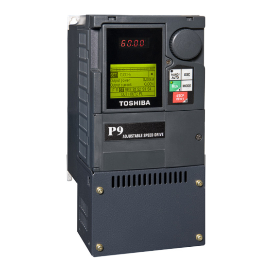
Electronic Operator Interface The P9 ASD Electronic Operator Interface (EOI) is comprised of an LED screen, an LCD screen, two LEDs, a rotary encoder, and five keys. These items are shown and described on EOI Operation The EOI is the primary input/output device for the user. The EOI may be used to monitor system functions, input data into the system, perform diagnostics, and view performance data (e.g., motor frequency, bus voltage, torque, etc.). -
Page 37: Real-Time Clock Setting
place. This ensures the proper alignment and electrical connection of the CNX connector of the LED/LCD display unit PCB. Gently hold the display in place while securing the Phillips mounting screw. If improperly seated, the periphery of the LED/LCD display unit will not be flush with the EOI surface and the unit will not function properly. -
Page 38: Eoi Features
EOI Features Figure 21. The P9 ASD Electronic Operator Interface Features. LED Screen Rotary Encoder LCD Screen Hand/Auto Key (LED) Escape Key Run Key (LED) HAND Mode /AUTO Stop-Reset Key LED Screen — Displays the running frequency, active Fault, or active Alarm information. Rotary Encoder —... - Page 39 Stop-Reset Key — This key has three functions. Issues the Off command (decelerates to Stop at the programmed rate) if pressed once while in the Hand mode in accordance with the setting of F721. Initiates an Emergency Off Fault if pressed twice quickly from the Hand or Auto modes. The Emergency Off function terminates the P9 ASD output and stops the motor in accordance with the setting of F603.
- Page 40 Using the LCD Screen The LCD screen is the primary user input/output information center. Parameter settings may be viewed or changed using the LCD display unit of the EOI. To view or change a parameter setting using the LCD screen, press the Mode key until the Program menu is displayed. Turn the Rotary Encoder until the desired Primary Menu item (See 52) is within the cursor block.
-
Page 41: Eoi Remote Mounting
EOI Remote Mounting The P9 ASD may be controlled from a remotely-mounted EOI. For safety and application-specific reasons, some ASD installations will warrant that the operator not be in the vicinity during operation or that the EOI not be attached to the ASD housing. Remote mounting will also allow for multiple EOI mountings at one location if controlling and monitoring several ASDs from a central location is required. - Page 42 EOI Installation Precautions Install the unit securely in a well ventilated area that is out of direct sunlight using the four mounting holes at the rear of the EOI. The ambient operating temperature rating is 14° to 104° F (-10° to 40° C). •...
- Page 43 EOI Remote Mounting Using the ASD-MTG-KIT-P9 SD-MTG- IT-P9 Note: See Figure 26 for the dimensions and the item locations referenced in steps through 6. At the EOI mounting location, mark the 4.60” by 4.50” hole and the four 11/32” screw holes. Cut the 4.60”...
-
Page 44: System Operation
System Operation Initial Setup The Standard Startup Wizard is run from Program\Utilities\Standard Startup Wizard and is used to assist the user with the initial configuration of the input power settings and the output signal parameters of the ASD. The Standard Startup Wizard is comprised of the more commonly used parameters of the ASD. - Page 45 Standard Startup Wizard Parameter Requirements The Standard Startup Wizard queries the user for information on the I/O signal parameters, control, and the EOI display settings of the ASD. The ASD may also be setup by directly accessing each of the startup settings via the Program menu or the associated Direct Access Numbers (See the section titled...
- Page 46 Volts per Hertz Setting (F015) This function establishes the relationship between the output frequency and the output voltage of the ASD. Settings: Constant Torque Voltage Decrease Curve Automatic Torque Boost Sensorless Vector Control (Speed) Sensorless Vector Control (Speed/Torque Switching) V/f 5-Point Curve (Go to F190 to Configure the V/f 5-Point Settings) PM Drive (Permanent Magnet)
-
Page 47: Operation (Hand)
Frequency Reference Source (F004) This selection allows the user to establish the source of the Frequency command. Settings: Use VI/II (V/I) Use RR Use RX EOI Keypad RS485 Communication Option Board RX2 Option (AI1) Option V/I UP/DOWN Frequency Pulse Input (Option) Pulse Input (Motor CPU) Binary/BCD Input (Option) Display Unit (F701) -
Page 48: Default Setting Changes
Default Setting Changes To change a default parameter setting, go to the root level of the Program menu. Turn the Rotary Encoder until the desired parameter group is within the cursor block. Press the Rotary Encoder to select an item or to access a subgroup (repeat if required until reaching the parameter to be changed). Press the Rotary Encoder to enter the Edit mode and the value/setting takes on the reverse video format (dark background/light text). -
Page 49: Saving User Settings
Saving User Settings Save User Settings A profile of an existing setup (user-settable parameters) may be saved and re-loaded when required by using the Save User Settings/Restore User Settings feature or via the Save/Restore Wizard. Both Save functions are accessed via the Utilities menu. Save/Restore User Settings The Save User Settings feature is selection seven (7) of the Program\Utilities\Type Reset menu. -
Page 50: Command Mode And Frequency Mode Control
Command Mode and Frequency Mode Control Command control includes instructions such as Stop, Run, Jog, etc. The source of the Command signal must be established for normal operation. Frequency commands control the output speed of the P9 ASD. The source of the frequency control signal must be established for normal operation. -
Page 51: Frequency Control (F004)
Frequency Control (F004) The Frequency Mode 1 (or the Frequency Mode 2) setting establishes the user-selected source of the frequency-control input for the P9 ASD. The signal source selected here is used for speed control unless the Reference Priority Selection parameter is configured to switch this setting automatically (See F200) or if the Override feature is enabled. -
Page 52: Override Operation
Placing the P9 ASD in the Hand mode (Hand/Auto LED on) via the EOI places the RS485 (2-wire) control selection in the Override Mode for Command and Frequency input (See the section titled Override Operation for the proper setting). The Hand/Auto control Override feature for Command and Frequency (or either) may be enabled/disabled at Program Utilities Prohibition Hand/ Auto Key (Command or Frequency) Override. - Page 53 Command Control Selections The following is a listing with descriptions of the Command Mode (F003) selections (Program Fundamental Standard Mode Selection Command Mode Selection). Settings: 0 — Terminal Block (Default) Allows for Command control input via the Terminal Board.
- Page 54 7 — Communication Option Board Use this setting if using the optional Communication Board for frequency control. 8 — RX2 Option (AI1) Used for a -10 to +10-volt DC analog input signal. 9 — Option V/I Allows for the use of the optional voltage/current frequency-control interface. 10 —...
-
Page 55: System Configuration And Menu Options
System Configuration and Menu Options Root Menus The Mode key accesses the three primary modes of the P9 ASD: the Frequency Command mode, the Monitor mode, and the Program mode. From either mode, press the Mode key to loop through to the other two modes (See Figure 28). - Page 56 EOI Command Mode The EOI Command mode is accessed by pressing the ESC key from the Frequency Command screen. With the exception of the VLP Control Enable/Disable, the control settings of the EOI Command menu are effective for EOI control only. The EOI Command mode provides quick access to the following menu parameters: Direction —...
- Page 57 Monitor Mode Monitored tems The Monitor mode allows the user to monitor motor performance variables, control settings, and configuration data during motor operation. There are 43 items that may be monitored from this mode. The items are listed and described below. Note: The Monitor mode is a read-only mode.
- Page 58 Feedback (Inst) — Provides a status of the Real-Time Feedback in Hz. Feedback (1 Second) — Provides a status of the 1-Second Averaging feedback in Hz. Torque — Displays the Output Torque as a percentage of the rated capacity of the P9 ASD. Torque Reference —...
- Page 59 Past Trip 3 — Past trip information or None. Past Trip 4 — Past trip information or None. Note: An improper P9 ASD setup may cause some trips — reset the P9 ASD to the Factory Default settings before pursuing a systemic malfunction (Program Utilities ...
- Page 60 Program Mode Menu Navigation ogram The following table lists the menu items of the Program mode and maps the flow of the menu selections. The Parameter Numbers for the listed functions are provided where applicable. The functions listed may be viewed, or selected and changed as mapped below or via the Direct Access method: Program ...
- Page 61 Program Mode Menu Navigation Parameter Primary Menu Sub Menu Parameter Name Number Output Terminal 1 (OUT1) Function F130 IRTUAL INEAR VLP Run External Devices Output Terminal 2 (OUT2) Function F131 VLP Low Suction/No-Flow Cut Off Mode F483 VLP Low Suction/No-Flow Cut Off Delay Timer F484 VLP Low Suction/No- Flow Cut Off...
- Page 62 Program Mode Menu Navigation Parameter Primary Menu Sub Menu Parameter Name Number Frequency Settings Time Limit for Lower-Limit Frequency Operation F256 UNDAMENTAL Automatic Torque Boost F001 Base Frequency 1 F014 Motor Set 1 Manual Torque Boost 1 F016 Motor Overload Protection Level 1 F600 Command Mode F003...
- Page 63 Program Mode Menu Navigation Parameter Primary Menu Sub Menu Parameter Name Number FP Terminal Assignment F676 ERMINAL Analog Output Terminals FP Terminal Frequency F677 Forward/Reverse Run Priority When Both Are Activated F105 Input Terminal Priority F106 Input Special 16-Bit Binary/BCD Input F107 Functions V/I Analog Input Broken Wire Detection Level...
- Page 64 Program Mode Menu Navigation Parameter Primary Menu Sub Menu Parameter Name Number Input Terminal 17 (B12) Function F164 ERMINAL Input Terminal 18 (B13) Function F165 Input Terminal 19 (B14) Function F166 Input Terminal 20 (BI5) Function F167 Input Terminals Virtual Input Terminal Selection 1 F973 Virtual Input Terminal Selection 2 F974...
- Page 65 Program Mode Menu Navigation Parameter Primary Menu Sub Menu Parameter Name Number Standard Startup See the section titled Initial Setup on pg. 36 for Startup TILITIES Wizard Wizard Requirements. Hand/Auto Key Command Override rohibited Hand/Auto Key Frequency Override Prohibition Show Uninitialized Parameters at Changed From Default Screen Over-Current Alarm ASD Overload Alarm...
- Page 66 Program Mode Menu Navigation Parameter Primary Menu Sub Menu Parameter Name Number Trip Number TILITIES Trip Type Frequency at Trip Output Current Output Voltage Direction Frequency Reference DC Voltage Discrete Input Terminals Discrete Output Terminals Run Timer Post Compensation Frequency Speed Feedback (Real Time) Trip History (read-only) Speed Feedback (1 Second)
- Page 67 Program Mode Menu Navigation Parameter Primary Menu Sub Menu Parameter Name Number Free Unit Multiplication Factor F702 Free Unit F703 Free Unit Display Gradient Characteristic F705 Display Parameters Free Unit Display Bias F706 Change Step Selection 1 F707 Change Step Selection 2 F708 Monitor 1 Main Monitor...
- Page 68 Program Mode Menu Navigation Parameter Primary Menu Sub Menu Parameter Name Number Emergency Off F603 ROTECTION Emergency Off Settings Emergency DC Injection Braking Control Time F604 Low-Current Trip F610 Low-Current Detection Current F611 Low-Current Settings Low-Current Detection Time F612 Low-Current Detection Hysteresis Width F609 Motor Overload Protection Configuration F017...
- Page 69 Program Mode Menu Navigation Parameter Primary Menu Sub Menu Parameter Name Number Synchronized Deceleration Time F317 ROTECTION Synchronized Acceleration Time F318 Under-Voltage/ Under-Voltage Trip F627 Ridethrough Under-Voltage (Trip Alarm) Detection Time F628 Regenerative Power Ridethrough Control Level F629 Short Circuit Detection at Start F613 Cooling Fan Control F620...
- Page 70 Program Mode Menu Navigation Parameter Primary Menu Sub Menu Parameter Name Number Preset Speed 9 F288 REQUENCY Preset Speed 10 F289 Preset Speed 11 F290 Preset Speeds Preset Speed 12 F291 Preset Speed 13 F292 Preset Speed 14 F293 Preset Speed 15 F294 V/I Input Point 1 Setting F201...
- Page 71 Program Mode Menu Navigation Parameter Primary Menu Sub Menu Parameter Name Number PG Input Point 2 Frequency F237 REQUENCY V/I Input Bias F470 V/I Input Gain F471 RR Input Bias F472 RR Input Gain F473 Speed Reference RX Input Bias F474 Setpoints RX Input Gain...
- Page 72 Program Mode Menu Navigation Parameter Primary Menu Sub Menu Parameter Name Number V/f 5-Point Setting Frequency 1 F190 PECIAL V/f 5-Point Setting Voltage 1 F191 V/f 5-Point Setting Frequency 2 F192 V/f 5-Point Setting Voltage 2 F193 V/f 5-Point Setting Frequency 3 F194 V/f 5-Point Setting V/f 5-Point Setting Voltage 3...
- Page 73 Program Mode Menu Navigation Parameter Primary Menu Sub Menu Parameter Name Number Panel Tension Torque Bias F727 PECIAL Panel Load Sharing Gain F728 Panel Override Multiplication Gain F729 Operation Panel Parameters Panel Frequency Lock Out F730 Panel Emergency Off Lock Out F734 Panel Reset Lock Out F735...
- Page 74 Program Mode Menu Navigation Parameter Primary Menu Sub Menu Parameter Name Number Motor Constant 2 (No Load Current) F411 OTOR Vector Motor Model Motor Constant 3 (Leak Inductance) F412 Motor Constant 4 (Rated Slip) F413 Power Running Torque Limit 2 Level F444 ORQUE Torque Settings...
- Page 75 Program Mode Menu Navigation Parameter Primary Menu Sub Menu Parameter Name Number Reverse Speed Limit Input F427 ORQUE Torque Control Reverse Speed Limit Input Level F428 Power Running Torque Limit 1 F440 Power Running Torque Limit 1 Level F441 Torque Limit Settings Regenerative Braking Torque Limit 1 F442 Regenerative Braking Torque Limit 1 Level...
- Page 76 Program Mode Menu Navigation Parameter Primary Menu Sub Menu Parameter Name Number Process Decreasing Rate F373 EEDBACK Feedback Settings Speed PI Switching Frequency F466 Adding Input Selection F660 Override Control Multiplying Input Selection F661 Number of PG Input Pulses F375 Number of PG Input Phases F376 PG Disconnection Detection...
- Page 77 Program Mode Menu Navigation Parameter Primary Menu Sub Menu Parameter Name Number Input Function Target 1 F912 UNCTION Input Function Command 1 F913 Input Function Target 2 F914 My Function Unit 3 Input Function Command 2 F915 Input Function Target 3 F916 Output Function Assigned F917...
- Page 78 Program Mode Menu Navigation Parameter Primary Menu Sub Menu Parameter Name Number My Function Percent Data 1 F918 UNCTION My Function Percent Data 2 F919 My Function Percent Data 3 F920 My Function Percent Data 4 F921 My Function Percent Data 5 F922 My Function Frequency Data 1 F923...
- Page 79 Program Mode Menu Navigation Parameter Primary Menu Sub Menu Parameter Name Number Frequency Point Selection F810 OMMUNICATIONS ommunications Point 1 Setting F811 Settings Communication Point 1 Frequency F812 Adjustments Point 2 Setting F813 Point 2 Frequency F814 Baud Rate (2-Wire RS485) F800 Parity (2-Wire and 4-Wire RS485) F801...
- Page 80 Program Mode Menu Navigation Parameter Primary Menu Sub Menu Parameter Name Number ASD Operation at Disconnection F851 OMMUNICATIONS Preset Speed Operation F852 Communication Option Station Address Monitor F853 Communication Option Speed Switch Monitor F854 DeviceNet/CC-Link Block Write Data 1 F870 Block Write Data 2 F871 Communication...
- Page 81 Program Mode Menu Navigation Parameter Primary Menu Sub Menu Parameter Name Number Preset Speed 3 ATTERN Direction Acceleration/Deceleration Group F563 V/f Group Torque Limit Group Preset Speed 4 Direction Acceleration/Deceleration Group F564 V/f Group Torque Limit Group Preset Speed 5 Direction Acceleration/Deceleration Group F565...
- Page 82 Program Mode Menu Navigation Parameter Primary Menu Sub Menu Parameter Name Number Preset Speed 9 ATTERN Direction Acceleration/Deceleration Group F569 V/f Group Torque Limit Group Preset Speed 10 Direction Acceleration/Deceleration Group F570 V/f Group Torque Limit Group Preset Speed 11 Direction Acceleration/Deceleration Group F571...
- Page 83 Program Mode Menu Navigation Parameter Primary Menu Sub Menu Parameter Name Number Preset Speed 15 ATTERN Direction Operation Mode Acceleration/Deceleration Group F575 V/f Group Torque Limit Group Speed 1 Operation Time F540 Speed 2 Operation Time F541 Speed 3 Operation Time F542 Speed 4 Operation Time F543...
- Page 84 Program Mode Menu Navigation Parameter Primary Menu Sub Menu Parameter Name Number Pattern Group 1, Selection 7 F529 ATTERN Pattern Group 1, Selection 8 F530 Pattern Group 2, Selection 1 F532 Pattern Group 2, Selection 2 F533 Pattern Group 2, Selection 3 F534 Speeds Pattern Group 2, Selection 4...
-
Page 85: Virtual Linear Pump
Virtual Linear Pump Toshiba International Corporation’s Virtual Linear Pump (VLP) algorithm allows for direct and precise control of pressure, flow rate, or level. This is achieved without the concerns, instabilities, or complexities that are traditionally associated with pumping system control. - Page 86 DANGER WARNING! — THE FOLLOWING STEP WILL START THE MOTOR! Figure 31. The VLP Maximum Value. 10. Set the system for normal flow VLP Setup Wizard and ensure that all system valves are set for normal operation. Back Next Exit 11.
- Page 87 Figure 33. Complete the VLP Setup. 16. Press the Stop key to complete VLP Setup Wizard the VLP setup. Back Next Exit 17. Click Exit to save settings Press [STOP] (Exit available at zero Hz). Virtual Linear Pump Setup Is Now Complete Figure 34.
- Page 88 Figure 35. Run the Motor/Pump in Process Hold Mode. 21. From the Frequency Command screen press ESC, scroll to the VLP Control field, and select Process Hold if using feedback (if not using feedback go to Step 18. on pg. 79).
-
Page 89: Direct Access Parameter Information
F000 F001 Direct Access Parameter Information The P9 ASD has the ability to allow the user direct access to the motor control functions. There are two ways in which the motor control parameters may be accessed for modification from the EOI: Program Applicable Menu Path or Program ... - Page 90 F003 F004 Command Mode Selection Direct Access Number — F003 Parameter Type — Selection List Program Fundamental Standard Mode Selection Factory Default — Terminal Block The Command Mode Selection establishes the source of the command input Changeable During Run — No for the ASD.
- Page 91 F005 F006 FM Output Terminal Function Direct Access Number — F005 Parameter Type — Selection List Program Terminal Analog Output Terminals Factory Default — Output Frequency This parameter is used to set the output function of the FM analog output Changeable During Run —...
- Page 92 F007 F008 Reset Type Reset Direct Access Number — F007 Parameter Type — Selection List Program Utilities Factory Default — None This feature assists the user when performing fault analysis or by allowing a Changeable During Run — No quick system setup change when required. Performing a Type Reset results in one of the following user-selected post-Reset configurations.
- Page 93 F009 F011 Acceleration Time 1 Direct Access Number — F009 Parameter Type — Numerical Program Fundamental Accel/Decel 1 Settings Factory Default — (ASD-Dependent) This parameter specifies the time in seconds for the output of the ASD to go Changeable During Run — Yes from 0.0 Hz to the Maximum Frequency for the 1 Acceleration profile.
- Page 94 F012 F015 Upper-Limit Frequency Direct Access Number — F012 Parameter Type — Numerical Program Fundamental Frequency Settings Factory Default — 66.0 This parameter sets the highest frequency that the ASD will accept as a Changeable During Run — Yes frequency command or frequency setpoint. The ASD may output frequencies Minimum —...
- Page 95 F016 F017 Manual Torque Boost 1 Direct Access Number — F016 Parameter Type — Numerical Program Fundamental Motor Set 1 Factory Default — (ASD-Dependent) The Manual Torque Boost 1 function is used to increase the low frequency Changeable During Run — Yes torque for high-inertia loads by increasing the output voltage at frequencies Minimum —...
- Page 96 F018 F019 Preset Speed 1 Direct Access Number — F018 eset Speed 1 Parameter Type — Numerical Program Frequency Preset Speeds Factory Default — 0.0 Up to fifteen (15) output frequency values that fall within the Lower-Limit and the Upper-Limit range may be programmed into the ASD and output as a Changeable During Run —...
- Page 97 F020 F024 eset Speed 3 Preset Speed 3 Direct Access Number — F020 Parameter Type — Numerical Program Frequency Preset Speeds Factory Default — 0.0 This parameter assigns an output frequency to binary number 0011 and is Changeable During Run — Yes identified as Preset Speed 3.
- Page 98 F040 F040 Automatic Function Selection Direct Access Number — F040 Parameter Type — Selection List Program Utilities Display Parameters Factory Default — Disabled This parameter setting is used to configure multiple parameters with the setting Changeable During Run — No of only one parameter.
- Page 99 F100 F105 Low-Speed Signal Output Frequency Direct Access Number — F100 Parameter Type — Numerical Program Terminal Reach Settings Factory Default — 0.00 The Low-Speed Signal Output Frequency parameter sets an ASD output Changeable During Run — Yes frequency threshold that activates the assigned discrete output terminal for the Minimum —...
- Page 100 F106 F107 Input Terminal Priority Direct Access Number — F106 Parameter Type — Selection List Program Terminal Input Special Functions Factory Default — Disabled This parameter is used to allow the Jog and DC Injection Braking input Changeable During Run — No signals to control the ASD when received via the Terminal Board even though the system is in the Hand mode.
- Page 101 F109 F113 Option V/I Terminal Voltage/Current Selection Direct Access Number — F109 Parameter Type — Selection List Program Frequency V/I Settings Factory Default — Voltage Input This parameter is used to set the AI2 input terminal to receive either current or Changeable During Run —...
- Page 102 F114 F118 Input Terminal 4 (RES) Function Direct Access Number — F114 Parameter Type — Selection List Program Terminal Input Terminals Factory Default — Reset Reset This parameter is used to set the functionality of the RES discrete input Changeable During Run — No terminal.
- Page 103 F119 F121 Input Terminal 9 (LI1) Function Direct Access Number — F119 Parameter Type — Selection List Program Terminal Input Terminals Factory Default — Unassigned This parameter is used to set the functionality of the LI1 discrete input terminal. Changeable During Run — No In addition, this input terminal must be specified as Normally Open or Normally Closed.
- Page 104 F122 F124 Input Terminal 12 (LI4) Function Direct Access Number — F122 Parameter Type — Selection List Program Terminal Input Terminals Factory Default — Unassigned This parameter is used to set the functionality of the LI4 discrete input terminal. Changeable During Run — No In addition, this input terminal must be specified as Normally Open or Normally Closed.
- Page 105 F125 F131 Input Terminal 15 (LI7) Function Direct Access Number — F125 Parameter Type — Selection List Program Terminal Input Terminals Factory Default — Unassigned This parameter is used to set the functionality of the LI7 discrete input terminal. Changeable During Run — No In addition, this input terminal must be specified as Normally Open or Normally Closed.
- Page 106 F132 F134 Output Terminal 3 (FL) Function Direct Access Number — F132 Parameter Type — Selection List Program Terminal Output Terminals Factory Default — Fault (All) This parameter is used to set the functionality of the FL output terminals to one Changeable During Run —...
- Page 107 F135 F137 Output Terminal 6 (R1) Function Direct Access Number — F135 Parameter Type — Selection List Program Terminal Output Terminals Factory Default — Always OFF This parameter is used to set the functionality of the R1 discrete output Changeable During Run — No terminal.
- Page 108 F138 F142 Output Terminal 9 (R2) Function Direct Access Number — F138 Parameter Type — Selection List Program Terminal Output Terminals Factory Default — Always Off This parameter is used to set the functionality of the R2 discrete output Changeable During Run — No terminal.
- Page 109 F143 F165 Input Terminal 4 (RES) Response Time Direct Access Number — F143 Parameter Type — Numerical Program Terminal Input Terminal Delays Factory Default — 8.0 This parameter delays the response of the ASD to any change in the RES Changeable During Run —...
- Page 110 F166 F169 Input Terminal 19 (B14) Function Direct Access Number — F166 Parameter Type — Selection List Program Terminal Input Terminals Factory Default — Unassigned This parameter is used to set the functionality of the B14 discrete input Changeable During Run — No terminal.
- Page 111 F170 F173 Base Frequency 2 Direct Access Number — F170 Parameter Type — Numerical Program Motor Motor Set 2 Factory Default — 60.0 The Base Frequency 2 setting is the frequency at which the output voltage of Changeable During Run — No the ASD reaches its maximum setting.
- Page 112 F174 F177 Base Frequency 3 Direct Access Number — F174 Parameter Type — Numerical Program Motor Motor Set 3 Factory Default — 60.0 The Base Frequency 3 setting is the frequency at which the output voltage of Changeable During Run — No the ASD reaches its maximum setting.
- Page 113 F178 F181 Base Frequency 4 Direct Access Number — F178 Parameter Type — Numerical Program Motor Motor Set 4 Factory Default — 60.0 The Base Frequency 4 setting is the frequency at which the output voltage of Changeable During Run — No the ASD reaches its maximum setting.
- Page 114 F190 F190 V/f 5-Point Setting Frequency 1 Direct Access Number — F190 Parameter Type — Numerical Program Special V/f 5-Point Setting Factory Default — 0.00 The V/f 5-Point Setting Frequency 1 setting establishes the frequency that is Changeable During Run — No to be associated with the voltage setting of F191 (V/f 5-Point Setting Voltage...
- Page 115 F191 F192 V/f 5-Point Setting Voltage 1 Direct Access Number — F191 Parameter Type — Numerical Program Special V/f 5-Point Setting Factory Default — 0.0 The V/f 5-Point Setting Voltage 1 establishes the output voltage level that is to Changeable During Run — No be associated with the frequency setting of F190 (V/f 5-Point Setting Frequency...
- Page 116 F193 F197 V/f 5-Point Setting Voltage 2 Direct Access Number — F193 Parameter Type — Numerical Program Special V/f 5-Point Setting Factory Default — 0.0 The V/f 5-Point Setting Voltage 2 establishes the output voltage level that is to Changeable During Run — No be associated with the frequency setting of F192 (V/f 5-Point Setting...
- Page 117 F198 F200 V/f 5-Point Setting Frequency 5 Direct Access Number — F198 Parameter Type — Numerical Program Special V/f 5-Point Setting Factory Default — 0.00 The V/f 5-Point Setting Frequency 5 sets the frequency to be associated with Changeable During Run — No the voltage setting of parameter F199 (V/f 5-Point Setting Voltage 5).
- Page 118 F201 F201 V/I Input Point 1 Setting Direct Access Number — F201 Parameter Type — Numerical Program Frequency Speed Reference Setpoints Factory Default — 0 This parameter is used to set the gain and bias of the isolated V/I input terminal Changeable During Run —...
- Page 119 F202 F204 V/I Input Point 1 Frequency Direct Access Number — F202 Parameter Type — Numerical Program Frequency Speed Reference Setpoints Factory Default — 0.00 This parameter is used to set the gain and bias of the V/I input terminal when Changeable During Run —...
- Page 120 F205 F205 V/I Input Point 1 Rate Direct Access Number — F205 Parameter Type — Numerical Program Torque Setpoints Factory Default — 0.00 This parameter is used to set the gain and bias of the isolated V/I input terminal Changeable During Run — Yes when the V/I terminal is used as the control input while operating in the Torque Minimum —...
- Page 121 F206 F208 V/I Input Point 2 Rate Direct Access Number — F206 Parameter Type — Numerical Program Torque Setpoints Factory Default — 100.00 This parameter is used to set the gain and bias of the V/I input terminal when Changeable During Run — Yes the V/I terminal is used as the control input while operating in the Torque Minimum —...
- Page 122 F209 F209 Analog Input Filter Direct Access Number — F209 Parameter Type — Selection List Program Frequency Analog Filter Factory Default — None Analog filtering is applied after the analog reference signal is converted to a Changeable During Run — Yes digital signal.
- Page 123 F210 F211 RR Input Point 1 Setting Direct Access Number — F210 Parameter Type — Numerical Program Frequency Speed Reference Setpoints Factory Default — 0 This parameter is used to set the gain and bias of the RR input terminal when Changeable During Run —...
- Page 124 F212 F213 RR Input Point 2 Setting Direct Access Number — F212 Parameter Type — Numerical Program Frequency Speed Reference Setpoints Factory Default — 100 This parameter is used to set the gain and bias of the RR input terminal when Changeable During Run —...
- Page 125 F214 F215 RR Input Point 1 Rate Direct Access Number — F214 Parameter Type — Numerical Program Torque Setpoints Factory Default — 0.00 This parameter is used to set the gain and bias of the RR input terminal when Changeable During Run — Yes the RR terminal is used as the control input while operating in the Torque Minimum —...
- Page 126 F216 F217 RX Input Point 1 Setting Direct Access Number — F216 Parameter Type — Numerical Program Frequency Speed Reference Setpoints Factory Default — 0 This parameter is used to set the gain and bias of the RX input terminal when Changeable During Run —...
- Page 127 F218 F219 RX Input Point 2 Setting Direct Access Number — F218 Parameter Type — Numerical Program Frequency Speed Reference Setpoints Factory Default — +100 This parameter is used to set the gain and bias of the RX input terminal when Changeable During Run —...
- Page 128 F220 F221 RX Input Point 1 Rate Direct Access Number — F220 Parameter Type — Numerical Program Torque Setpoints Factory Default — 0.00 This parameter is used to set the gain and bias of the RX input terminal when Changeable During Run — Yes the RX terminal is used as the control input while operating in the Torque Minimum —...
- Page 129 F222 F222 RX2 (AI1) Input Point 1 Setting Direct Access Number — F222 Parameter Type — Numerical Program Frequency Speed Reference Setpoints Factory Default — 0 This parameter is used to set the gain and bias of the RX2 (AI1) input terminal Changeable During Run —...
- Page 130 F223 F225 RX2 (AI1) Input Point 1 Frequency Direct Access Number — F223 Parameter Type — Numerical Program Frequency Speed Reference Setpoints Factory Default — 0.00 This parameter is used to set the gain and bias of the RX2 (AI1) input terminal Changeable During Run —...
- Page 131 F226 F226 RX2 (AI1) Input Point 1 Rate Direct Access Number — F226 Parameter Type — Numerical Program Torque Setpoints Factory Default — 0.00 This parameter is used to set the gain and bias of the RX2 (AI1) input terminal Changeable During Run —...
- Page 132 F227 F227 RX2 (AI1) Input Point 2 Rate Direct Access Number — F227 Parameter Type — Numerical Program Torque Setpoints Factory Default — 100.00 This parameter is used to set the gain and bias of the RX2 (AI1) input terminal Changeable During Run —...
- Page 133 F228 F228 BIN Input Point 1 Setting Direct Access Number — F228 Parameter Type — Numerical Program Frequency Speed Reference Setpoints Factory Default — 0 This parameter is used to set the gain and bias of the BIN input terminals when Changeable During Run —...
- Page 134 F229 F231 BIN Input Point 1 Frequency Direct Access Number — F229 Parameter Type — Numerical Program Frequency Speed Reference Setpoints Factory Default — 0.00 This parameter is used to set the speed of the BIN input terminals when the Changeable During Run —...
- Page 135 F234 F235 PG Input Point 1 Setting Direct Access Number — F234 Parameter Type — Numerical Program Frequency Speed Reference Setpoints Factory Default — 0.0 This parameter is used to set the gain and bias of the PG input terminal of the Changeable During Run —...
- Page 136 F236 F241 PG Input Point 2 Setting Direct Access Number — F236 Parameter Type — Numerical Program Frequency Speed Reference Setpoints Factory Default — 0 This parameter is used to set the direction and speed of the PG input terminals Changeable During Run —...
- Page 137 F242 F251 Run Frequency Hysteresis Direct Access Number — F242 Parameter Type — Numerical Program Special Frequency Control Factory Default — 0.00 This parameter provides a plus-or-minus value for the Run Frequency setting Changeable During Run — Yes (F241). Minimum — 0.00 Maximum —...
- Page 138 F252 F256 DC Injection Braking Time Direct Access Number — F252 Parameter Type — Numerical Program Protection DC Braking Factory Default — 1.0 This parameter setting is used to set the on-time duration of the DC Injection Changeable During Run — Yes Braking.
- Page 139 F260 F261 Jog Run Frequency Direct Access Number — F260 Parameter Type — Numerical Program Frequency Jog Settings Factory Default — 0.00 This parameter sets the output frequency of the ASD during a Jog. Jogging is Changeable During Run — Yes the term used to describe turning on the motor for small increments of time and Minimum —...
- Page 140 F262 F262 EOI (Panel) Operation Jog Mode Direct Access Number — F262 Parameter Type — Selection List Program Frequency Jog Settings Factory Default — Disabled This parameter enables the Jog command to be received from the EOI. When Changeable During Run — Yes disabled the Jog command received from the EOI is ignored.
- Page 141 F264 F264 UP/DOWN Frequency (up) Response Time Direct Access Number — F264 Parameter Type — Numerical No Path — Direct Access Only Factory Default — 0.1 This parameter functions in conjunction with the parameter settings of F265, F266, F267, F268, and F269. The purpose of these settings is to set up the ASD Changeable During Run —...
- Page 142 F265 F269 UP/DOWN Frequency (up) Frequency Step Direct Access Number — F265 Parameter Type — Numerical No Path — Direct Access Only Factory Default — 0.10 This parameter sets the frequency increase amount for each activation of the Changeable During Run — Yes UP/DOWN Frequency (up) terminal activation.
- Page 143 F270 F270 Figure 36. UP/Down Frequency Operation Control Timing Diagram. Jump Frequency 1 Direct Access Number — F270 Parameter Type — Numerical Program Special Jump Frequencies Factory Default — 0.00 In conjunction with parameter F271, this parameter establishes a user-defined Changeable During Run —...
- Page 144 F271 F287 Jump Frequency 1 Bandwidth Direct Access Number — F271 Parameter Type — Numerical Program Special Jump Frequencies Factory Default — 0.00 This parameter establishes a plus-or-minus value for Jump Frequency 1 ( Changeable During Run — Yes F270). Minimum —...
- Page 145 F288 F293 Preset Speed 9 Direct Access Number — F288 Parameter Type — Numerical Program Frequency Preset Speeds Factory Default — 0.0 This parameter assigns an output frequency to binary number 1001 and is Changeable During Run — Yes identified as Preset Speed 9. The binary number is applied to S1 – S4 of the Minimum —...
- Page 146 F294 F301 Preset Speed 15 Direct Access Number — F294 Parameter Type — Numerical Program Frequency Preset Speeds Factory Default — 0.00 This parameter assigns an output frequency to binary number 1111 and is Changeable During Run — Yes identified as Preset Speed 15. The binary number is applied to S1 – S4 of the Minimum —...
- Page 147 F302 F302 Regenerative Power Ridethrough Mode Direct Access Number — F302 Parameter Type — Selection List Program Protection Under-Voltage/Ridethrough Factory Default — Off This parameter determines the motor control response of the ASD in the event of a momentary power outage or under-voltage condition. Changeable During Run —...
- Page 148 F303 F303 Retry Selection Direct Access Number — F303 Parameter Type — Numerical Program Protection Retry/Restart Factory Default — 00 After a trip has occurred, this parameter sets the number of times that an automatic system restart is attempted for a qualified trip. Changeable During Run —...
- Page 149 F304 F305 Dynamic Braking Selection Direct Access Number — F304 Parameter Type — Selection List Program Protection Dynamic Braking Factory Default — Off This parameter Enables/Disables the Dynamic Braking system. Changeable During Run — No Settings: 0 — Off 1 — On with Overload Detection 2 —...
- Page 150 F307 F310 Supply Voltage Correction Direct Access Number — F307 Parameter Type — Selection List Program Protection Base Frequency Voltage Factory Default — Disabled This parameter Enables/Disables the Voltage Compensation function. Changeable During Run — No When Enabled, this function provides a constant V/f ratio during periods of input voltage fluctuations.
- Page 151 F311 F317 Forward Run/Reverse Run Disable Direct Access Number — F311 Parameter Type — Selection List Program Frequency Forward/Reverse Disable Factory Default — Off This parameter Enables/Disables the Forward Run or Reverse Run mode. Changeable During Run — No If either direction is disabled, commands received for the disabled direction will not be recognized.
- Page 152 F318 F322 Synchronized Acceleration Time Direct Access Number — F318 Parameter Type — Numerical Program Protection Under-Voltage/Ridethrough Factory Default — 2.0 In the event that the Ridethrough function activates in a multiple-motor Changeable During Run — Yes application it will be necessary to manage the accelerating motors Minimum —...
- Page 153 F323 F342 Drooping Insensitive Torque Direct Access Number — F323 Parameter Type — Numerical Program Feedback Drooping Control Factory Default — 10.00 This parameter defines a torque range in which the Drooping Control settings Changeable During Run — Yes will be ignored and the programmed torque settings will be followed. Minimum —...
- Page 154 F343 F347 Panel Torque Bias Direct Access Number — F343 Parameter Type — Numerical Program Torque Torque Control Factory Default — 100.00 Once enabled at parameter F341, this parameter establishes the torque bias Changeable During Run — Yes setting to which the setting of F342 will either add to or subtract from to Minimum —...
- Page 155 F348 F350 Braking Time Learning Function Direct Access Number — F348 Parameter Type — Selection List Program Torque Torque Control Factory Default — Disabled This parameter is used to establish approximate settings for parameters F343, Changeable During Run — Yes F345, F346, and F347.
- Page 156 F351 F353 Acceleration Suspend Time Direct Access Number — F351 Parameter Type — Numerical Program Fundamental Accel/Decel 1 Settings Factory Default — 0.0 When Enabled at F349, this parameter is used to set the duration of activation Changeable During Run — Yes of the Acceleration Suspend function when initiated by reaching the Minimum —...
- Page 157 F354 F354 Commercial Power/ASD Output Switching Direct Access Number — F354 Parameter Type — Selection List Program Terminal Line Power Switching Factory Default — Off This parameter Enables/Disables the Commercial Power/ASD Output Changeable During Run — No Switching function. When enabled, the system may be set up to discontinue using the output of the ASD and to switch to the commercial power if 1) a trip is incurred, 2) a user-set ASD frequency is reached, or 3) if initiated by a discrete input terminal.
- Page 158 F355 F359 Commercial Power/ASD Switching Frequency Direct Access Number — F355 Parameter Type — Numerical Program Terminal Line Power Switching Factory Default — 60.00 When enabled at F354 and with a properly configured discrete output terminal, Changeable During Run — Yes this parameter sets the frequency at which the At Frequency Powerline Minimum —...
- Page 159 F360 F364 PID Feedback Signal Direct Access Number — F360 Parameter Type — Selection List Program Feedback Feedback Settings Factory Default — V/I This parameter Enables/Disables PID feedback control. When enabled, this Changeable During Run — Yes parameter determines the source of the motor control feedback. Settings: 0 —...
- Page 160 F365 F370 PID Deviation Lower-Limit Direct Access Number — F365 Parameter Type — Numerical Program Feedback Feedback Settings Factory Default — 60.00 This parameter determines the maximum amount that the feedback may Changeable During Run — Yes decrease the output signal. Minimum —...
- Page 161 F371 F376 PID Output Lower-Limit Direct Access Number — F371 Parameter Type — Numerical Program Feedback Feedback Settings Factory Default — 4.00 Selecting Speed PID at parameter F359 allows for this parameter setting to Changeable During Run — Yes function as the Lower-Limit while operating in the PID Control mode. Minimum —...
- Page 162 F377 F382 PG Disconnection Detection Direct Access Number — F377 Parameter Type — Selection List Program Feedback PG Settings Factory Default — (ASD-Dependent) This parameter Enables/Disables the system’s monitoring of the PG connection Changeable During Run — No status when using encoders with line driver outputs. Note: The PG Vector Feedback Board option is required to use this feature.
- Page 163 F383 F385 VLP Sleep Timer Delay Direct Access Number — F383 Parameter Type — Numerical Virtual Linear Pump Sleep Timer Setting Factory Default — 300 During a properly configured VLP operation, and once enabled at F382, this Changeable During Run — Yes parameter establishes the time that system operation will be allowed to operate Minimum —...
-
Page 164: Figure 42-G
F387 F389 VLP Auto Start-Stop Delay Timer Direct Access Number — F387 Parameter Type — Numerical Virtual Linear Pump Auto Start-Stop Delay Timer Factory Default — 5.0 During a properly configured VLP operation, this parameter establishes the Changeable During Run — Yes time that the Start-Stop criteria of F388 F389... - Page 165 F390 F392 Virtual Linear Pump Mode Switch Direct Access Number — F390 Parameter Type — Selection List Program Virtual Linear Pump VLP Settings Factory Default — Disabled This parameter is enabled for use by completing the VLP Setup Wizard. Changeable During Run — No During a properly configured VLP operation, this parameter establishes if feedback is used or not.
- Page 166 F393 F396 Virtual Linear Pump Transducer Maximum Reading Direct Access Number — F393 Parameter Type — Numerical Program Virtual Linear Pump VLP Settings Factory Default — 0 During a properly configured VLP operation, this parameter establishes the Changeable During Run — Yes maximum level of the transducer range for VLP operation.
- Page 167 F397 F400 Process Hold Operation VLP Command Value via the EOI Direct Access Number — F397 Parameter Type — Numerical Program Virtual Linear Pump VLP Settings Factory Default — 0.0 During a properly configured VLP operation while operating in the Process Changeable During Run —...
- Page 168 F401 F403 Slip Frequency Gain Direct Access Number — F401 Parameter Type — Numerical Program Motor Vector Motor Model Factory Default — 70 This parameter provides a degree of slip compensation for a given load. A Changeable During Run — Yes higher setting here decreases the slip allowed for a given load/ASD output ratio.
- Page 169 F404 F406 Time-Based Alternation Emergency Timer Direct Access Number — F404 Parameter Type — Numerical Program Virtual Linear Pump VLP Time-Based Alternation Factory Default — 60 During Time-Based Alternation operation, in the event that the Lead ASD Changeable During Run — Yes trips or loses the transducer input signal, this parameter sets a counter time that, Minimum —...
- Page 170 F407 F413 Motor Rated RPM Direct Access Number — F407 Parameter Type — Numerical Program Motor Vector Motor Model Factory Default — 1730 This parameter is used input the (nameplated) rated speed of the motor. Changeable During Run — No Minimum —...
- Page 171 F415 F416 Exciting Strengthening Coefficient Direct Access Number — F415 Parameter Type — Numerical Program Special Special Parameters Factory Default — 100 This parameter is used to increase the magnetic flux of the motor at low-speed. Changeable During Run — No This feature is useful when increased torque at low speeds is required.
- Page 172 F417 F420 Time-Based Alternation Direct Access Number — F417 Parameter Type — Selection List Program Virtual Linear Pump VLP Time-Based Alternation Factory Default — Off This parameter is enabled for use by completing the VLP Setup Wizard. Changeable During Run — Yes Time-Based Alternation operation is enable by setting this parameter (F417) to an operating mode and assigning a discrete input terminal to the TBA HOA The active TBA ASD is indicated by...
- Page 173 F423 F425 Tension Torque Bias Input Direct Access Number — F423 Parameter Type — Selection List Program Torque Torque Control Factory Default — Disabled This parameter Enables/Disables the Tension Torque Bias input function. Changeable During Run — Yes This feature is enabled by selecting a Tension Torque Bias input signal source. Settings: 0 —...
- Page 174 F426 F430 Forward Speed Limit Level Direct Access Number — F426 Parameter Type — Numerical Program Torque Torque Control Factory Default — 80.0 This parameter provides a value to be used as the Forward Speed Limit setting Changeable During Run — Yes F426 is selected at F425.
- Page 175 F431 F437 Speed Limit (torque=0) Center Value Direct Access Number — F431 Parameter Type — Numerical Program Torque Torque Speed Limiting Factory Default — 0.00 This parameter provides a value to be used as the Speed Limit (torque=0) Changeable During Run — Yes Center Value Reference setting if F431 is selected at F430.
- Page 176 F438 F442 Time-Based Alternation Process Hold Mode Response Time Direct Access Number — F438 Parameter Type — Numerical Program Virtual Linear Pump VLP Time-Based Alternation Factory Default — 7.5 During Time-Based Alternation operation, while running in the Process Hold Changeable During Run — No mode, this parameter sets the time that the system may operate within the Minimum —...
- Page 177 F443 F448 Regenerative Braking Torque Limit 1 Level Direct Access Number — F443 Parameter Type — Numerical Program Torque Torque Limit Settings Factory Default — 250.0 (Disabled) This parameter provides a value to be used as the Regeneration Torque Limit Changeable During Run —...
- Page 178 F449 F452 Regenerative Braking Torque Limit 4 Level Direct Access Number — F449 Parameter Type — Numerical Program Torque Manual Torque Limit Settings Factory Default — 250.0 (Disabled) This parameter is used to set the negative torque upper-limit for the 4 motor Changeable During Run —...
- Page 179 F453 F462 Stall Prevention During Regeneration Direct Access Number — F453 Parameter Type — Selection List Program Protection Stall Factory Default — Enabled This function of this parameter is to disable the Over-Voltage Stall (F305) and Changeable During Run — Yes the Over-Current Stall (F017) function during regeneration only.
- Page 180 F463 F470 Second Speed Loop Proportional Gain Direct Access Number — F463 Parameter Type — Numerical Program Feedback PG Settings Factory Default — 12 During closed-loop operation, this parameter sets the sensitivity of the ASD Changeable During Run — No when monitoring the output speed for control.
- Page 181 F471 F474 V/I Input Gain Direct Access Number — F471 Parameter Type — Numerical Program Frequency Speed Reference Setpoints Factory Default — 129 This parameter is used to fine tune the gain of the V/I input terminals. Changeable During Run — Yes Note: See note on pg.
- Page 182 F475 F478 RX Input Gain Direct Access Number — F475 Parameter Type — Numerical Program Frequency Speed Reference Setpoints Factory Default — 127 This parameter is used to fine tune the gain of the RX input terminal when this Changeable During Run —...
- Page 183 F479 F479 AI2 (Option V/I) Input Gain Direct Access Number — F479 Parameter Type — Numerical Program Frequency Speed Reference Setpoints Factory Default — 128 This parameter is used to fine tune the gain of the Optional AI2 input terminal Changeable During Run —...
- Page 184 F480 F480 xternal Device VLP External Device Delay Timer Direct Access Number — F480 Parameter Type — Numerical Virtual Linear Pump External Device Delay Timer xternal Factory Default — 5 evice 2 During a properly configured VLP operation, this parameter establishes the Changeable During Run —...
- Page 185 F481 F483 VLP Low Band Threshold Direct Access Number — F481 Parameter Type — Numerical Virtual Linear Pump Low Band Threshold Factory Default — 10 During a properly configured VLP operation, this parameter establishes the Changeable During Run — Yes upper limit of the VLP Minimum Zone.
- Page 186 F484 F486 Low Suction Pressure Delay Timer Direct Access Number — F484 Parameter Type — Numerical Virtual Linear Pump Low Suction Pressure Delay Timer Factory Default — 10 This parameter has three functions. Changeable During Run — Yes It is used to set the time that the ASD will be allowed to run at the Upper- Minimum —...
- Page 187 F487 F500 Process Hold Operation VLP Command Value via Direct Access Number — F487 Communications Parameter Type — Numerical Program Virtual Linear Pump VLP Settings Factory Default — 0.0 Changeable During Run — Yes During a properly configured VLP operation while operating in the Process Minimum —...
- Page 188 F501 F501 Deceleration Time 2 Direct Access Number — F501 Program Fundamental Accel/Decel 1 Settings Parameter Type — Numerical Factory Default — (ASD-Dependent) This parameter specifies the time in seconds for the output of the ASD to go Changeable During Run — Yes from the Maximum Frequency to 0.0 Hz for the 2 Deceleration profile.
- Page 189 F502 F502 Acceleration/Deceleration Pattern 1 Direct Access Number — F502 Parameter Type — Selection List Program Special Accel/Decel 1 – 4 Settings Factory Default — Linear This parameter enables a user-selected preprogrammed output profile that Changeable During Run — Yes controls the acceleration and deceleration pattern for the 1 Accel/Decel parameters ( F009...
- Page 190 F503 F503 Acc/Dec Pattern 2 Direct Access Number — F503 Parameter Type — Selection List Program Special Accel/Decel 1 – 4 Settings Factory Default — Linear This parameter enables a user-selected preprogrammed output profile that Changeable During Run — Yes controls the acceleration and deceleration pattern for the 2 Accel/Decel parameter.
- Page 191 F504 F505 Acc/Dec Pattern 1 – 4 Direct Access Number — F504 Parameter Type — Selection List Program Special Acc/Dec Special Factory Default — 1 Four Acceleration times and four Deceleration times may be set up and run individually. Accel/Decel Time 1 – 4 may be selected using this parameter Changeable During Run —...
- Page 192 F506 F510 S-Pattern Acceleration Lower-Limit Adjustment Direct Access Number — F506 Parameter Type — Numerical Program Special Accel/Decel Special Factory Default — 10 During an S-Pattern 1 or 2 sequence, this parameter settings modifies the Changeable During Run — Yes acceleration rate for the lower part of the acceleration curve by the percentage Minimum —...
- Page 193 F511 F514 Deceleration Time 3 Direct Access Number — F511 Parameter Type — Numerical Program Special Accel/Decel 1 – 4 Settings Factory Default — (ASD-Dependent) This parameter specifies the time in seconds for the output of the ASD to go Changeable During Run —...
- Page 194 F515 F521 Deceleration Time 4 Direct Access Number — F515 Parameter Type — Numerical Program Special Accel/Decel 1 – 4 Settings Factory Default — (ASD-Dependent) This parameter specifies the time in seconds for the output of the ASD to go Changeable During Run —...
- Page 195 F522 F522 Pattern 1 Repeat Direct Access Number — F522 Parameter Type — Numerical Program Pattern Run Pattern Run Factory Default — 255 (Infinite) This parameter sets the number of times to repeat the Pattern Group 1. Changeable During Run — No Settings: Minimum —...
- Page 196 F523 F523 Pattern Group 1 Selection 1 Direct Access Number — F523 Parameter Type — Selection List Program Pattern Run Speeds Factory Default — Skip Groups of configured Preset Speeds may be selected and run from this screen. Changeable During Run — No The execution of grouped Preset Speeds in this manner is called a Pattern Minimum —...
- Page 197 F524 F527 Pattern Group 1 Selection 2 Direct Access Number — F524 Parameter Type — Selection List Program Pattern Run Speeds Factory Default — Skip This parameter allows the user to select 1 of 15 configured Preset Speeds as Changeable During Run — No the number 2 Selection to be included in Pattern Group 1.
- Page 198 F528 F531 Pattern Group 1 Selection 6 Direct Access Number — F528 Parameter Type — Selection List Program Pattern Run Speeds Factory Default — Skip This parameter allows the user to select 1 of 15 configured Preset Speeds as Changeable During Run — No the number 6 Selection to be included in Pattern Group 1.
- Page 199 F532 F535 Pattern Group 2 Selection 1 Direct Access Number — F532 Parameter Type — Selection List Program Pattern Run Speeds Factory Default — Skip This parameter allows the user to select 1 of 15 configured Preset Speeds as Changeable During Run — No the number 1 selection to be included in the Group 2 Selection.
- Page 200 F536 F539 Pattern Group 2 Selection 5 Direct Access Number — F536 Parameter Type — Selection List Program Pattern Run Speeds Factory Default — Skip This parameter allows the user to select 1 of 15 configured Preset Speeds as Changeable During Run — No the number 5 selection to be included in the Group 2 Selection.
- Page 201 F540 F545 Speed 1 Operation Time Direct Access Number — F540 Parameter Type — Numerical Program Pattern Run Operation Time Factory Default — 5.0 This parameter sets the run-time for Preset Speed 1. Changeable During Run — Yes This time is effective when used with Group Speeds and non-Group Speeds. Minimum —...
- Page 202 F546 F551 Speed 7 Operation Time Direct Access Number — F546 Parameter Type — Numerical Program Pattern Run Operation Time Factory Default — 5.0 This parameter sets the run-time for Preset Speed 7. Changeable During Run — Yes This time is effective when used with Group Speeds and non-Group Speeds. Minimum —...
- Page 203 F552 F560 Speed 13 Operation Time Direct Access Number — F552 Parameter Type — Numerical Program Pattern Run Operation Time Factory Default — 5.0 This parameter sets the run-time for Preset Speed 13. Changeable During Run — Yes This time is effective when used with Group Speeds and non-Group Speeds. Minimum —...
- Page 204 F561 F563 Preset Speed 1 Operation Mode Direct Access Number — F561 Parameter Type — Selection List Program Pattern Run Operation Mode Factory Default — Forward Run This parameter is enabled at F560 and is used to set the speed, torque, and Changeable During Run —...
- Page 205 F564 F573 Preset Speed 4 Operation Mode Direct Access Number — F564 Parameter Type — Selection List Program Pattern Run Operation Mode Factory Default — Forward Run Same as Preset Speed 1 Operation Mode ( F561). Changeable During Run — No Preset Speed 5 Operation Mode Direct Access Number —...
- Page 206 F574 F602 Preset Speed 14 Operation Mode Direct Access Number — F574 Parameter Type — Selection List Program Pattern Run Operation Mode Factory Default — Forward Run Same as Preset Speed 1 Operation Mode ( F561). Changeable During Run — No Preset Speed 15 Operation Mode Direct Access Number —...
- Page 207 F603 F605 Emergency Off Mode Settings Direct Access Number — F603 Parameter Type — Selection List Program Protection Emergency Off Settings Factory Default — Coast Stop This parameter determines the method used to stop the motor in the event that Changeable During Run —...
- Page 208 F606 F610 Overload Reduction Starting Frequency Direct Access Number — F606 Parameter Type — Numerical Program Protection Overload Factory Default — 6.00 This parameter is primarily used with V/f motors. It is used to reduce the Changeable During Run — Yes starting frequency at which the Overload Reduction function begins and is Minimum —...
- Page 209 F611 F615 Low-Current Detection Threshold Direct Access Number — F611 Parameter Type — Numerical Program Protection Low-Current Settings Factory Default — 0 With the Low-Current Trip (F610) parameter is enabled, this function sets the Changeable During Run — Yes low-current trip threshold. Minimum —...
- Page 210 F616 F621 Over-Torque Detection Level (Positive Torque) Direct Access Number — F616 Parameter Type — Numerical Program Protection Over-Torque Parameters Factory Default — 200.00 This parameter sets the torque threshold level that is used as a setpoint for over- Changeable During Run — Yes torque tripping during positive torque.
- Page 211 F622 F627 Abnormal Speed Detection Time Direct Access Number — F622 Parameter Type — Numerical Program Protection Abnormal Speed Settings Factory Default — 0.01 This parameter sets the time that an over-speed condition must exist to cause a Changeable During Run — Yes trip.
- Page 212 F628 F631 Under-Voltage Trip Detection Time Direct Access Number — F628 Parameter Type — Numerical Program Protection Under-Voltage/Ridethrough Factory Default — 0.03 This parameter sets the time that the under-voltage condition must exist to cause an Under-Voltage Trip. Changeable During Run — No This parameter is enabled at F627.
- Page 213 F633 F637 V/I Analog Input Broken Wire Detection Level Direct Access Number — F633 Parameter Type — Numerical Program Terminal Input Special Functions Factory Default — 0 (Disabled) This parameter is enabled by providing a non-zero value here. This function Changeable During Run —...
- Page 214 F638 F641 PTC2 Thermal Selection Direct Access Number — F638 Parameter Type — Selection List Program Special Special Parameters PTC2 Thermal Selection Factory Default — Disabled This parameter Enables/Disables the optional external thermal detection circuit Changeable During Run — No of the Expansion IO Card Option 2.
- Page 215 F644 F661 V/I Analog Input Loss Response Direct Access Number — F644 Parameter Type — Selection List Program Terminal Input Special Functions Factory Default — Trip This parameter is used to provide a system disposition in the event of the loss of Changeable During Run —...
- Page 216 F670 F672 AM Output Terminal Function Direct Access Number — F670 Parameter Type — Selection List Program Terminal Analog Output Terminals Factory Default — Output Current This parameter is used to set the output function of the AM analog output Changeable During Run —...
- Page 217 F673 F676 MON1 Terminal Adjustment Direct Access Number — F673 Parameter Type — Numerical Program Terminal Analog Output Terminals Factory Default — 512 This parameter is used to set the gain of the MON1 output terminal and is used Changeable During Run — Yes in conjunction with the settings of parameter F672.
- Page 218 F677 F685 FP Terminal Frequency Direct Access Number — F677 Parameter Type — Numerical Program Terminal Analog Output Terminals Factory Default — 3.84 This parameter scales the FP output terminal by setting the pulses-per-second Changeable During Run — Yes output signal of the FP terminal. Minimum —...
- Page 219 F686 F691 AM Bias Adjustment Direct Access Number — F686 Parameter Type — Numerical Program Terminal Analog Output Terminals Factory Default — 0.0 This parameter setting is used to ensure that a zero-level input signal produces a Changeable During Run — Yes zero-level output at the AM terminal.
- Page 220 F692 F702 MON 2 Output Gradient Characteristic Direct Access Number — F692 Parameter Type — Selection List Program Terminal Analog Output Terminals Factory Default — Plus This parameter sets the output response polarity of the MON2 output terminal. Changeable During Run — Yes The MON2 output terminal response may be set to respond inversely (-) or directly (+) to the input signal.
- Page 221 F703 F707 Display Unit Selection Direct Access Number — F703 Parameter Type — Selection List Program Utilities Display Parameters Factory Default — All Frequencies This parameter is used in conjunction with F702 to set the method in which the Changeable During Run — Yes frequency is displayed on the EOI.
- Page 222 F708 F721 Change Step Selection 2 Direct Access Number — F708 Parameter Type — Numerical Program Utilities Display Parameters Factory Default — 0 (Disabled) The parameter is used to modify the degree that the setting of F707 affects the Changeable During Run — Yes output speed changes that are input from the EOI using the Rotary Encoder.
- Page 223 F725 F734 Panel Torque Command Direct Access Number — F725 Parameter Type — Numerical Program Special Operation Panel Parameters Factory Default — 0.00 This function is not used with the P9 ASD. Changeable During Run — Yes The Torque Command selection is performed at F420. Minimum —...
- Page 224 To acquire and store the data a communications device and a PC are required. The P9 ASD supports the following communications protocols: RS485 (MODBUS-RTU) Toshiba Protocol, USB Toshiba Protocol, CC-Link, ProfiBus, and DeviceNet (Refer to the manual of each protocol type for more information).
- Page 225 F741 F745 Trace Cycle Direct Access Number — F741 Parameter Type — Selection List Program Utilities Trace Factory Default — 100 mS This parameter sets the record time for the Trace Data events selected at F742 – F745. Changeable During Run — Yes F740 for more information on this parameter setting.
- Page 226 F800 F803 Baud Rate (RS485 2-Wire) Direct Access Number — F800 Parameter Type — Selection List Program Communications Communication Settings Factory Default — 19200 This parameter plays a role in the setup of the communications network by establishing the Baud Rate of the communications link. Changeable During Run —...
- Page 227 F804 F805 Communications Time-Out Action (RS485 2- and 4-wire) Direct Access Number — F804 Parameter Type — Selection List Program Communications Communication Settings Factory Default — Trip/Trip This parameter plays a role in the setup of the communications network by Changeable During Run —...
- Page 228 F806 F810 ASD-to-ASD Communications (RS485 2-wire) Direct Access Number — F806 Parameter Type — Selection List Program Communications Communication Settings Factory Default — Follower (Decel Stop) The function of this parameter is 2-fold: Changeable During Run — Yes 1) In a Master/Follower configuration and while communicating via RS485 2-wire, this parameter sets the ASD as the Master or the Follower.
- Page 229 F811 F813 Point 1 Setting Direct Access Number — F811 Parameter Type — Numerical Program Communications Communication Reference Adjust Factory Default — 0 When enabled at F810, this parameter is used to allow the user to set the gain Changeable During Run — Yes and bias of the speed control input to the ASD when the speed control signal is Minimum —...
- Page 230 F814 F825 Point 2 Frequency Direct Access Number — F814 Parameter Type — Numerical Program Communications Communication Reference Adjust Factory Default — 60.00 This parameter is used to set the gain and bias of the Communications Changeable During Run — Yes Reference speed control input.
- Page 231 6 — Master (Output Torque) RS485 Protocol Selection Direct Access Number — F829 Parameter Type — Selection List Program Communications Communication Settings Factory Default — Toshiba This parameter sets the communications protocol for ASD-to-ASD Changeable During Run — Yes communications. Settings: 0 —...
- Page 232 F831 F836 Communications Option (DeviceNet/Profibus) Setting 2 Direct Access Number — F831 Parameter Type — Selection List Program Communications Communication Settings Factory Default — 0000h While using the DeviceNet/Profibus communications protocol, parameters Changeable During Run — Yes F831 – F836 allow the user to select the ASD memory location that holds the Command/Frequency/Monitoring instructions to be applied to the ASD for Communications Option Settings 2 –...
- Page 233 F841 F844 Communications Option (DeviceNet/Profibus) Setting 8 Direct Access Number — F841 Parameter Type — Selection List Program Communications Communication Settings Factory Default — 0000h While using the DeviceNet/Profibus communications protocol, parameters Changeable During Run — Yes F841 – F846 allow the user to select the ASD memory location that holds the Command/Frequency/Monitoring instructions to be applied to the ASD for Communications Option Settings 8 –...
- Page 234 F845 F853 Communications Option (DeviceNet/Profibus) Setting 12 Direct Access Number — F845 Parameter Type — Selection List Program Communications Communication Settings Factory Default — 0000h Same as F841. See F841 for information on this parameter. Changeable During Run — Yes Communications Option (DeviceNet/Profibus) Setting 13 Direct Access Number —...
- Page 235 F854 F871 Communications Option Speed Switch Monitor DeviceNet/ Direct Access Number — F854 CC-Link Parameter Type — Hardware Selectable Program Communications Communication Settings Factory Default — Option-Specific Changeable During Run — No This parameter is used in the setup of the communications network by reading Minimum —...
- Page 236 F876 F877 Block Read Data 1 Direct Access Number — F875 Parameter Type — Selection List Program Communications Communication Settings Factory Default — 0 (None) This parameter plays a role in the setup of the communications network by Changeable During Run — Yes establishing the type of data to be read from the ASD using the communications link.
- Page 237 F878 F901 Block Read Data 4 Direct Access Number — F878 Parameter Type — Selection List Program Communications Communication Settings Factory Default — None This parameter plays a role in the setup of the communications network by Changeable During Run — Yes establishing the type of data to be read from the ASD of the communications link.
- Page 238 F902 F905 Input Function Target 2 Direct Access Number — F902 Parameter Type — Selection List Program My Function My Function Unit 1 Factory Default — 0 (Disabled) This parameter plays a role in the setup of the My Function feature by Changeable During Run —...
- Page 239 F906 F910 Input Function Target 1 Direct Access Number — F906 Parameter Type — Selection List Program My Function My Function Unit 2 Factory Default — 0 (Disabled) This parameter plays a role in the setup of the My Function feature by Changeable During Run —...
- Page 240 F911 F915 Output Function Assigned Direct Access Number — F911 Parameter Type — Selection List Program My Function My Function Unit 2 Factory Default — 0 (Disabled) This parameter plays a role in the setup of the My Function feature by Changeable During Run —...
- Page 241 F916 F919 Input Function Target 3 Direct Access Number — F916 Parameter Type — Selection List Program My Function My Function Unit 3 Factory Default — 0 (Disabled) This parameter plays a role in the setup of the My Function feature by Changeable During Run —...
- Page 242 F920 F925 My Function Percent Data 3 Direct Access Number — F920 Parameter Type — Numerical Program My Function My Function Data Factory Default — 0.00 This parameter is used to set the trigger threshold level of the analog signal of Changeable During Run —...
- Page 243 F926 F930 My Function Frequency Data 4 Direct Access Number — F926 Parameter Type — Numerical Program My Function My Function Data Factory Default — 0.00 This parameter is used to set the trigger threshold level of the analog signal of Changeable During Run —...
- Page 244 F931 F935 My Function Time Data 4 Direct Access Number — F931 Parameter Type — Numerical Program My Function My Function Data Factory Default — 0.01 This parameter is used to set the response delay of the My Function Time Changeable During Run —...
- Page 245 F936 F940 Input Function Command 1 Direct Access Number — F936 Parameter Type — Selection List Program My Function My Function Unit 4 Factory Default — 0 (NOP) This parameter is used to assign a user-selected logical operator to two user- selected Input Function Target variables, enable a counter/timer function, or perform a hold/reset function.
- Page 246 F941 F945 Input Function Target 1 Direct Access Number — F941 Parameter Type — Selection List Program My Function My Function Unit 5 Factory Default — 0 (Disabled) This parameter plays a role in the setup of the My Function feature by Changeable During Run —...
- Page 247 F946 F950 Output Function Assigned Direct Access Number — F946 Parameter Type — Selection List Program My Function My Function Unit 5 Factory Default — 0 (Disabled) This parameter plays a role in the setup of the My Function feature by Changeable During Run —...
- Page 248 F951 F954 Input Function Target 3 Direct Access Number — F951 Parameter Type — Selection List Program My Function My Function Unit 6 Factory Default — 0 (Disabled) This parameter plays a role in the setup of the My Function feature by Changeable During Run —...
- Page 249 F955 F958 Input Function Target 2 Direct Access Number — F955 Parameter Type — Selection List Program My Function My Function Unit 7 Factory Default — 0 (Disabled) This parameter plays a role in the setup of the My Function feature by Changeable During Run —...
- Page 250 F959 F962 Analog Input Function Target 11 Direct Access Number — F959 Parameter Type — Selection List Program My Function My Function Analog Factory Default — 0 (Disabled) This parameter plays a role in the setup of the My Function feature by Changeable During Run —...
- Page 251 F964 F966 Analog Function Assigned Object 21 Direct Access Number — F964 Parameter Type — Selection List Program My Function My Function Analog Factory Default — 0 (Disabled) This parameter plays a role in the setup of the My Function feature by Changeable During Run —...
- Page 252 F967 F969 Monitor Output Function 21 Direct Access Number — F967 Parameter Type — Selection List Program My Function My Function Monitor Factory Default — 2000 This parameter plays a role in the setup of the My Function feature by Changeable During Run —...
- Page 253 F970 F972 Monitor Output Function Command 31 Direct Access Number — F970 Parameter Type — Selection List Program My Function My Function Monitor Factory Default — Normal This parameter plays a role in the setup of the My Function feature by allowing Changeable During Run —...
- Page 254 F973 F976 Virtual Input Terminal 1 Selection Direct Access Number — F973 Parameter Type — Selection List Program Terminal Input Terminals Factory Default — Unassigned This parameter is used to set the functionality of the Virtual Input Terminal 1. Changeable During Run — No As a virtual terminal, it exists only in memory and is considered to always be in its True (connected to CC) state.
- Page 255 F977 F977 My Function Selection Direct Access Number — F977 Parameter Type — Selection List Program My Function Factory Default — None (Disabled) This parameter Enables/Disables the configured My Function feature of the P9 ASD. Changeable During Run — No Settings: DANGER 0 —...
- Page 256 F977 (Cont.) F977 Combined Terminal Function Direct Access Number — F977 Parameter Type — Selection List Output terminals may also be combined to produce one output response to Factory Default — None (Disabled) multiple conditions using the computational operators of Table 12 on pg.
- Page 257 Table 6. Discrete Input Terminal Assignment Selections and Descriptions. Sel. No. Terminal Selection Descriptions NO NC Note: NO/NC = Normally Open/Normally Closed. NO/NC selection numbers are used when making system changes via communications. Unassigned — No operation. Forward — Provides a Forward run command. Reverse —...
- Page 258 Table 6. (Continued) Discrete Input Terminal Assignment Selections and Descriptions. Sel. No. Terminal Selection Descriptions NO NC Note: NO/NC = Normally Open/Normally Closed. NO/NC selection numbers are used when making system changes via communications. Torque Limit Switching 1/Torque Limit Switching 2 — Activating combinations of discrete input terminals Torque Limit Switching 1 and 2 allow for the selection of a torque limit switching profile as listed below.
- Page 259 Table 6. (Continued) Discrete Input Terminal Assignment Selections and Descriptions. Sel. No. Terminal Selection Descriptions NO NC Note: NO/NC = Normally Open/Normally Closed. NO/NC selection numbers are used when making system changes via communications Binary Write — Writes the status of the discrete input terminals to the control board during binary input speed control.
- Page 260 Table 6. (Continued) Discrete Input Terminal Assignment Selections and Descriptions. Sel. No. Terminal Selection Descriptions NO NC Note: NO/NC = Normally Open/Normally Closed. NO/NC selection numbers are used when making system changes via communications Sealing Water — Once an adequate water supply is detected at the pump seal via a reed switch, activation enables Sealing Water 140 141 the ASD for normal operations.
- Page 261 Table 7. Output Terminal Assignments for the FP, AM, FM, MON1, and MON2 Output Terminals. Output Meter Terminal Assignments and Display Item Selections Selection/ Selection/ Terminal Assignment Name Terminal Assignment Name Comm Number Comm Number utput Output Frequency 100% Meter Adjust Value equency Frequency Reference Data from Communications...
- Page 262 Table 8. My Function Input Function Target Selections. Selection/ Selection/ Communications Terminal Assignment Communications Terminal Assignment Number Number Unassigned Forward Reverse Standby Reset Virtual Input Terminal 1 Virtual Input Terminal 2 Virtual Input Terminal 3 Virtual Input Terminal 4 Internal Terminal 1 Internal Terminal 2 Internal Terminal 3 Internal Terminal 4...
- Page 263 Table 9. Output Terminal Assignments, My Function Input Setting Assignments, and Parameter/Input Setting Numbers for the FLA/B/C, O1A/O1B (OUT1), O2A/O2B (OUT2), OUT3 – OUT6, and R1 – R4. Discrete Output Terminal Assignment Selections Input Param. Input Param. Function Function Setting Setting Setting Setting...
- Page 264 Table 10. Trace Back Data Selections. Selection Number Comm. Number Trace (Monitor) Function Resolution/Unit FD00 Output Frequency 0.01 Hz FD02 Frequency Reference 0.01 Hz FD03 Output Current 0.01% FD04 DC Bus Voltage 0.01% FD05 Output Voltage 0.01% FD15 Compensated Frequency 0.01 Hz FD16 Speed Feedback (Real Time)
- Page 265 Table 11. Input Function Target Selections and the Associated Communications Number. Input Setting/Communication Number Resolution/ Monitor Function FM/AM/FP Comm. Comm. Unit Display Input Input Setting Number Number Setting 2000 FD00 3000 FE00 Output Frequency 0.01 Hz 2002 FD02 3002 FE02 Frequency Reference 0.01 Hz 2003...
- Page 266 Table 11. (Continued) Input Function Target Selections and the Associated Communications Number. Input Setting/Communication Number Resolution/ Monitor Function FM/AM/FP Comm. Comm. Unit Display Input Input Setting Number Number Setting 3050 FE50 Communication Data Output 2 3051 FE51 Communication Data Output 1 3052 FE52 Communication Data Output 3...
- Page 267 Table 12. My Function Operator Selections. My Function Computational Selections Input Function Function Name Function Description Command NOP (No Operation) Disables the My Function feature. Execute data read/transfer. Execute inverted data read/transfer. Logical product of A AND B. ANDN Logical product of A AND B. Logical sum of A OR B.
-
Page 268: Alarms, Trips, And Troubleshooting
Alarms, Trips, and Troubleshooting Alarm Alarms and Trips This section lists the available user-notification codes of the EOI display and provides information that assists the user in the event that a Fault is incurred. The User Notification codes are displayed as an indication that a system function or system condition is active (i.e., ATN, DB, and DBON). -
Page 269: User Notification Codes
User Notification Codes The User Notification codes appear in the top right corner of the Frequency Command screen while the associated function is active. User Notification codes notify the user of active functions that are usually only momentary under normal conditions and are active for the duration of activation only. -
Page 270: Alarms
Alarms Table 14 lists the alarm codes that may be displayed during operation of the P9 ASD. Each alarm code listed is accompanied by a description and a possible cause. In the event that the source of the malfunction cannot be determined, contact your TIC Sales Representative for further information on the condition and for an appropriate course of action. - Page 271 Description Possible Causes/Troubleshooting Screen Screen * Reset ignored if active. Overheat ASD ambient temperature • ASD is operating at an elevated temperature. excessive. • ASD is too close to heat-generating equipment. • Cooling fan vent is obstructed (see Mounting the ASD on pg.
- Page 272 Description Possible Causes/Troubleshooting Screen Screen * Reset ignored if active. Control Under-Voltage Under-voltage condition at the 5, • Defective Control board. *POFF 15, or the 24 VDC supply. • Excessive load on power supply. • Low input voltage. Reference Point Two speed-reference frequency •...
-
Page 273: Trips/Faults
Trips/Faults A Trip is an P9 ASD response to a Fault (though Fault and Trip are sometimes used interchangeably). A Trip is a safety feature that disables the ASD system in the event that a subsystem of the ASD is malfunctioning or a parameter setting has been exceeded. - Page 274 LED Screen LCD Screen Possible Causes/Troubleshooting Optional Expansion • Optional Expansion Input Terminal Board 1 is defective. E-23 Input Terminal Board 1 Error Optional Expansion • Optional Expansion Input Terminal Board 2 is defective. E-24 Input Terminal Board 2 Error Stop Positioning •...
- Page 275 LED Screen LCD Screen Possible Causes/Troubleshooting Flash Memory Fault • Flash memory malfunction. ERR9 • Make a service call. Autotune Error • No motor connected or improperly secured connection. • Autotune readings that are significantly inconsistent with the configuration information. •...
- Page 276 LED Screen LCD Screen Possible Causes/Troubleshooting Overheat During • Cooling fan inoperative. OC1P Acceleration • Ventilation openings are obstructed. • Internal thermistor is disconnected. • Acceleration time is too short. • Improper V/f setting. • ASD or the motor is improperly matched to the application. Over-Current During •...
- Page 277 LED Screen LCD Screen Possible Causes/Troubleshooting Overheat • Cooling fan inoperative. • Ventilation openings are obstructed. • Internal thermistor is disconnected. External Overheat • Excessive-heat signature received at the TB3 – TH1(+) and TH1(-) terminals. See F637 for setup information. ASD Overload •...
- Page 278 Viewing Trip Information In the event that the condition causing an Alarm does not return to the normal operating level within a specified time, the P9 ASD Faults and a Trip is incurred. When a trip occurs, the resultant error information may be viewed either from the LED screen, LCD Fault screen (Program ...
-
Page 279: Enclosure And Conduit Plate Dimensions
Enclosure and Conduit Plate Dimensions The P9 ASD part numbering convention is shown below. The enclosure dimensions for the available models (typeforms) are listed in Tables 17 and 18. The conduit plates referenced are shown in Figures 41, 42, and 43. P9 Part Numbering Convention. -
Page 280: Model Number Vt130P9U
Table 18. 460-Volt P9 ASD Systems. Mounting Hole Dimensions Enclosure Model Number (in/mm) Conduit Frame Figure Width Height Depth VT130P9U Plate Number (in/mm) (in/mm) (in/mm) 4015 4025 5.2/132 11.2/285 6.1/155 8.7/220 4.5/114 4035 0.217/5.5 Figure 41-A 0.098/2.5 4055 6.1/155 12.4/315 9.8/249 5.4/138 4080... - Page 281 Figure 38. See Tables 17 for Actual Dimensions. P9 ASD Installation and Operation Manual...
- Page 282 Figure 39. See Tables 17 for Actual Dimensions. P9 ASD Installation and Operation Manual...
- Page 283 Figure 40. See Tables 17 for Actual Dimensions. P9 ASD Installation and Operation Manual...
-
Page 284: Conduit Plate Dimensions
Conduit Plate Dimensions Figure 41. See Tables 17 for the associated device. Dimensions are in in/cm. P9 ASD Installation and Operation Manual... - Page 285 Figure 42. See Tables 17 for the associated device. Dimensions are in in/cm. P9 ASD Installation and Operation Manual...
- Page 286 Figure 43. See Table 18 for the associated device. Dimensions are in in/cm. P9 ASD Installation and Operation Manual...
-
Page 287: Current/Voltage Specifications
Current/Voltage Specifications Table 19. 230-Volt Chassis Standard Ratings Table. Model 100% Output Overload Current Input Voltage Output Voltage Typical Number Current 120% for 60 3-Ph 50/60 3-Ph Variable Motor HP VT130P9U Continuous Seconds ±2 Hz Frequency 2010 0.75 3.2 A 3.84 A 2015 4.2 A... - Page 288 Table 20. 460-Volt Chassis Standard Ratings Table. Model 100% Output Overload Current Input Voltage Output Voltage Typical Number Current 120% for 60 3-Ph 50/60 3-Ph Variable Motor HP VT130P9U Continuous Seconds ±2 Hz Frequency 4015 2.1 A 2.52 A 4025 3.4 A 4.08 A 4035...
-
Page 289: Cable/Terminal/Torque Specifications
Cable/Terminal/Torque Specifications ) (Requirements for Electrical Installations), all Installation should conform to the NEC Article 110 (NEC regulations of the Occupational Safety and Health Administration, and any other applicable national, regional, or industry codes and standards. Note: The following ratings are guidelines and shall not be the sole determining factor of the lug or wire size used with the P9 ASD. - Page 290 Table 22. 460-Volt P9 ASD Cable/Terminal/Torque Specifications. Terminal Wire/Cable Size Lug Size Range Board Torque Model AWG or kcmil MCP Rating Number (Amps) VT130P9U Wire-Size/Lug-Capacity TB1 – 4 Input/Output Power 3Ø-Input 3Ø-Output for Input/Output Power Terminals In-Lbs./Nm Recommended Maximum 3Ø-Input 3Ø-Output 4015 4025...
-
Page 291: Dynamic Braking Protection
Dynamic Braking Protection Thermal protection for the DBR circuit (see Figure 44. on pg. 284) or an input contactor that will open the 3-phase power input circuit (see Figure 45. on pg. 284) to the P9 ASD in the event that a DBR over- temperature condition occurs is a requirement. - Page 292 Figure 44. Braking Resistor Circuit With a Thermal Fuse. Figure 45. Shown below is the connection diagram using an MCCB with a Trip Coil (TC) in lieu of an input contactor. A control transformer is required for 400-volt models only. The primary MC is opened in the event of a DBR over-current detection.
-
Page 293: Short Circuit Protection Recommendations
Short Circuit Protection Recommendations Table 23. 230/240 and 400/480-Volt ASD Recommended Circuit Breaker Selection. Model Number Continuous Output Current Circuit Breaker Part Number VT130P9U (Amps) 2010 0.75 2015 HLL36015 2025 2035 HLL36025 2055 15.2 2080 22.0 HLL36040 2110 28.0 HLL36050 2160 42.0 HLL36070... -
Page 294: P9 Asd Optional Devices
P9 ASD Optional Devices The ASD may be equipped with several options which are used to expand the functionality. Table 24 lists the available options and their functions. Table 24. P9 Optional Devices and Functions. Part Identifier Device Name Device Function Used to connect the ASD to a PC via the USB port of the ASD-CAB-USB H9 USB Communication Cable... - Page 295 Index Numerics Analog Function Assigned Object 11, 242 Analog Function Assigned Object 21, 243 0 Hz Command Output, 130 Analog Input Filter, 114 0 Hz Dead Band Signal, 129 Analog Input Function Target 11, 242 16-Bit Binary/BCD Input, 92 Analog Input Function Target 21, 242 Analog Output Terminals, 54 Annual Average Ambient Temperature, 205 ASD Capacity, 13...
- Page 296 Bezel Plate Mounting Hardware, 33 Communications Option Speed Switch Monitor BIN Input Point 1 Frequency, 126 DeviceNet/CC-Link, 227 BIN Input Point 1 Setting, 125 Communications Option Station Address Monitor, 226 BIN Input Point 2 Frequency, 126 Communications Setting Changes, 40 BIN Input Point 2 Setting, 126 Communications Settings, 71 Block Read Data 1, 228...
- Page 297 Display Parameters, 58 EOI Mounting Dimensions, 34 Display Unit Multiplication Factor, 212 EOI Operation, 28 Display Unit Selection, 213 EOI Operation Jog Mode, 132 Display Units for Current and Voltage, 212 EOI Remote Mounting, 29 Disposal, 3 EOI Remote Mounting Using the ASD-MTG-KIT9, 35 Drooping, 144 EOI Remote Mounting w/o the ASD-MTG-KIT9, 34 Drooping Control, 67...
- Page 298 Forward Speed Limit Input, 165 Input Function Command 2, 230, 231, 232, 237, 238, Forward Speed Limit Level, 166 239, 241 Forward/Reverse DC Injection Braking Priority, 130 Input Function Target 1, 229, 231, 232, 236, 238, 239, Forward/Reverse Disable, 61 Forward/Reverse Run Priority Selection, 91 Input Function Target 2, 230, 231, 232, 237, 238, 239, Forward/Reverse Run Selection, 84...
- Page 299 Jump Frequency 1 Bandwidth, 136 MOFF, 262 Jump Frequency 2, 136 MON 1 Bias Adjustment, 211 MON 1 Output Gradient Characteristic, 211 Jump Frequency 2 Bandwidth, 136 MON 1 Voltage/Current Output Switching, 211 Jump Frequency 3, 136 MON 2 Bias Adjustment, 212 Jump Frequency 3 Bandwidth, 136 MON 2 Output Gradient Characteristic, 212 MON 2 Voltage/Current Output Switching, 211...
- Page 300 My Function Count Data 2, 236 OP, 263 My Function Frequency Data 1, 234 OP1, 269 OP2, 269 My Function Frequency Data 2, 234 OP3, 269 My Function Frequency Data 3, 234 Operation (Hand), 39 My Function Frequency Data 4, 235 Operation Above 60 Hz, 10 My Function Frequency Data 5, 235 Operation Command Clear Selection When ST Off, 214...
- Page 301 Over-Speed Detection Frequency Lower Band, 203 Pattern Group 2 Selection 6, 192 Over-Speed Detection Frequency Upper Band, 203 Pattern Group 2 Selection 7, 192 Over-Torque, 269 Pattern Group 2 Selection 8, 192 Over-Torque Detection Hysteresis, 202 Pattern Group Cycle, 50 Pattern Group Number, 50 Over-Torque Detection Level (Negative Torque), 202 Pattern Group Preset, 50...
- Page 302 Preset Speed 11, 137 RAM Fault, 266 Preset Speed 11 Operation Mode, 197 Random Mode, 143 Reach Settings, 56 Preset Speed 12, 137 Read Error, 266 Preset Speed 12 Operation Mode, 197 real-time clock, 270 Preset Speed 13, 137 Real-Time Clock Setup, 57 Preset Speed 13 Operation Mode, 197 reciprocating load, 11 Preset Speed 14, 137...
- Page 303 RX Input Point 2 Rate, 120 Speed 4 Operation Time, 193 RX Input Point 2 Setting, 119 Speed 5 Operation Time, 193 RX2, 50 Speed 6 Operation Time, 193 RX2 (AI1) Input Bias, 174 Speed 7 Operation Time, 194 RX2 (AI1) Input Gain, 174 Speed 8 Operation Time, 194 RX2 (AI1) Input Point 1 Frequency, 122 Speed 9 Operation Time, 194...
- Page 304 Time-Based Alternation Emergency Timer, 161 User Notification Codes, 261 Time-Based Alternation operation, 164 Using the LCD Screen, 32 Time-Based Alternation Period, 164 Utilities, 56 Time-Based Alternation Process Hold Mode Response Time, 168 Time-Based Alternation Pump Number, 167 Time-Based Alternation Total Number of ASDs, 167 V/f 5-Point Setting, 64 Torque, 50, 66 V/f 5-Point Setting Frequency 1, 106...
- Page 305 VLP Auto Start-Stop Lower Level Threshold, 156 VLP Sleep Timer Delay, 155 VLP Auto Start-Stop Mode, 155 VLP Start and Stop Points, 52 VLP Auto Start-Stop Upper Level Threshold, 156 Voltage and Frequency Rating of the Motor, 37 VLP Enable/Disable, 252 Volts Per Hertz Setting, 38 VLP External Device Delay Timer, 176 V-Phase Over-Current, 268...
- Page 306 TOSHIBA TOSHIBA INTERNATIONAL CORPORATION INDUSTRIAL DIVISION 13131 West Little York Road, Houston, TX 77041-5807 US (800) 231-1412 CAN (800) 872-2192 MEX 01 (800) 527-1204 FAX: (713) 466-8773 http://www.toshiba.com/ind/ Printed in the U.S.A.
Need help?
Do you have a question about the vlp technology P9 ASD and is the answer not in the manual?
Questions and answers