Toshiba BMS-CT2560U-E Service Manual
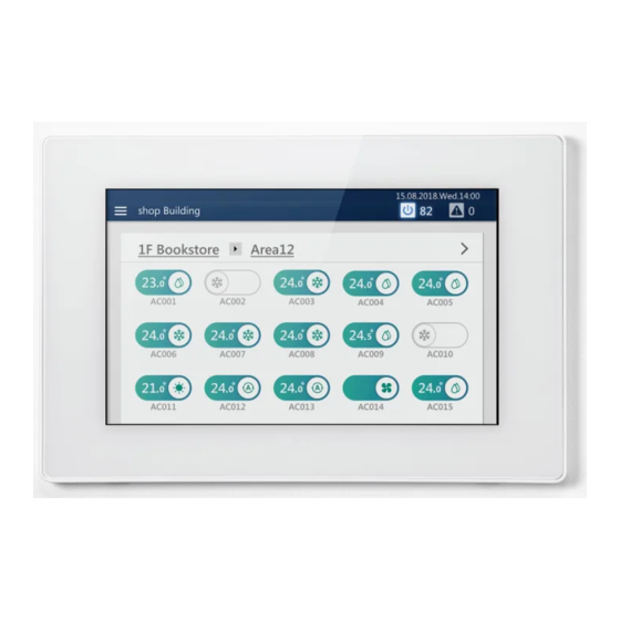
Touch screen controller
Hide thumbs
Also See for BMS-CT2560U-E:
- Installation manual (20 pages) ,
- Owner's manual (113 pages) ,
- Quick reference manual (2 pages)

Related Manuals for Toshiba BMS-CT2560U-E


Summary of Contents for Toshiba BMS-CT2560U-E
- Page 1 FILE No. A10-2009 Service Manual Touch Screen Controller Model name: BMS-CT2560U-E (BMS-CT1280TU) (BMS-CT2560U-TR) (BMS-CT2560U-UL) PRINTED IN JAPAN, NOV, 2020, TBEX...
-
Page 2: Table Of Contents
Contents Safety Precautions ............3 1 Product Overview . -
Page 3: Safety Precautions
Safety Precautions • This section explains safety precautions you must follow in order to prevent harm to the user and other persons and damage to property. • "Display Description" explains the classification of the degree of harm or damage that may occur if the unit is handled incorrectly, while "Symbol Description"... - Page 4 • After the work is completed, be sure to test between the live and dead metal parts (earth terminal) with an insulation resistance tester (500 V) to confirm that the insulation resistance is 2 MΩ or higher Insulation check A low insulation resistance value may result in a short circuit, electric shock or other accident on the customer's premises.
-
Page 5: Product Overview
Product Overview 1-1. Function list Specifications Detailed specifications Power supply 220-240 V AC 50/60 Hz Consumed current 1.17 A Operating temperature/ 0°C to 40°C, 10% to 90% RH (no dew condensation) humidity range Dimensions (mm) H136×W205×D10(+80) (Embedded dimensions shown in parenthesis) 1.34 kg (Touch Screen Controller) Mass 0.45 kg (power adapter) - Page 6 Function list Key Features Key Features Main unit 8 inputs ON/OFF Inputs DIO interface 8 inputs x 4 units Mode Power pulse measurement Set temp. Demand Interlocking Fan speed Fire Alarm Interlocking Wind direction Locking Interlocking External input Lock setting of remote control Stop Interlocking Ventilation →...
- Page 7 1-2. Basic Usage This section explains the basic setting method for operation Start/Stop and air conditioning, the setting method for the operation schedule, and the confirmation method for the overall air conditioning system. Start/Stop Operation Overall air conditioning system operation method Tap [ -(1)] or [ -(2)]...
- Page 8 Group unit operation method Scroll the home screen to display the group you want to change the settings for, then tap Tap [ -(1)] or [ -(2)] -(1) -(1) -(2) -(2) Check the contents of the message and tap [ -(1)] -(1) -(1)
- Page 9 When the screen on the left appears, check the contents of the message and tap [ -(1)] or [ -(2)] * All group air conditioners and ON/OFF equipment turn ON or OFF. -(2) -(2) -(1) -(1) * About confirmation pop-up selection Group General purpose External device...
- Page 10 Change the Air Conditioning Settings Group unit operation method Scroll the home screen to display the group you want to change the settings for, then tap Tap [ -(1)] The batch settings screen is displayed. -(1) -(1) Change settings Example: When changing the operation status settings Tap [ -(1)] -(1)
- Page 11 Name Functions Wind direction to switch to the following. ● NOTE Depending on the connected model, it may not be configurable. Fan Speed to switch to the following. ● NOTE Depending on the connected model, it may not be configurable. Set temp.
- Page 12 Check the contents of the message and tap [ -(1)] -(1) -(1) When the screen on the left appears, check the contents of the message and tap [ -(1)] or [ -(2)] * The settings of the entire group are changed. -(2) -(2) -(1)
- Page 13 Air conditioner unit operation method ● NOTE To change the settings, it is necessary to set to the operation status. (P.9) Scroll the home screen, display the air conditioner you want to change the settings for, then tap the switch Change settings Name Functions...
- Page 14 Name Functions Fan Speed Tap to switch to the following. ● NOTE Depending on the connected model, it may not be configurable. Set temp. to change the set temperature. ● NOTE • If the operation mode is FAN, the temperature cannot be set. •...
- Page 15 1-3. Scheduled functions Set the Operation Schedule You can configure the air conditioners or the ON/OFF unit with a “Weekly schedule”, through which settings such as operation start/stop are changed depending on the specified time for any day from Sunday to Saturday, or a “Special day schedule”, through which settings are changed for special days such as national holidays or special holidays.
- Page 16 Individual control screen The schedule set for the air conditioner or ON/OFF unit being displayed is displayed on a 24-hour time scale. Functions You can switch the display in day-of-week units. Displays the setting screen of Special day schedule. Displays the setting screen of Weekly schedule. is displayed at the times when the schedule is set.
- Page 17 Create a new weekly schedule In a Weekly schedule, you can set: • Start time • Day(s) of the week • Air conditioner(s) or ON/OFF unit • ON/OFF Schedule settings can be applied from either the group screen or the individual control screen. In the following procedure, the individual control screen is used to explain.
- Page 18 Select the air conditioner(s) or ON/OFF unit for setting the schedule and tap [ -(1)] You cannot select a model that has already been scheduled at the same time. -(1) -(1) Tap the check box of [ -(1)] and set it to , then select -(2)] or [ -(3)] and tap [...
- Page 19 Create a new special day schedule In a Special day schedule, you can register special days, such as national holidays and special holidays, to configure a special day schedule that differs from the Weekly schedule. Schedules can be configured from the group screen or the individual control screen. The following procedure is explained using the individual control screen.
- Page 20 Tap or flick to set the start date, and then tap [ -(1)] -(1) -(1) Tap the check box of [ -(1)] and set it to , then select -(2)] or [ -(3)] and tap [ -(4)] You can only set [ON/OFF] here. -(1) -(1) -(2)
- Page 21 Change the Operating Schedule The operating schedule settings can be changed from the [Menu] button, the group screen, or the individual control screen. There are two types of operating schedules: Weekly schedule and Special day schedule. The following procedure is explained using the individual control screen. ●...
- Page 22 Scroll the screen and tap the value of the item you want to set. After changing the setting, tap [OK] See "Setting items list" (P.25) for the items that can be configured.
- Page 23 Change the details of the special day schedule Tap [ -(1)] on the group screen or the individual control screen -(1) -(1) Tap [ -(1)] -(1) -(1) Tap [ -(1)] of the schedule you want to modify • [3-(1)] Unit setting: Go to step 4 -(2) -(2) -(1)
- Page 24 Tap [ -(1)] of the time you want to modify -(1) -(1) Scroll the screen and tap the value of the item you want to set. After changing the setting, tap [OK] See "Setting items list" (P.25) for the items that can be configured.
- Page 25 Setting items list Setting Items Setting Procedure Time setting [Start date] Tap or flick to change the time. Day of the week setting [week] Set the check box(es) of the day(s) of the week on which you want to execute the schedule ●...
- Page 26 Setting Items Setting Procedure Local operation prohibition setting Tap the check box of the function whose setting you want to change to set it to , then [Lock setting of remote control] select [(1)] or [(2)]. Night operation setting You can change the [ON/OFF] of the night operation of the target device. [Night operation] Save operation setting To enable the setting, set the check box of [(3)] to...
- Page 27 Delete the operation schedule You can delete the schedule from either the group screen or the individual control screen. In the following procedure, the individual control screen is used. Tap [ -(1)] on the group screen or individual control screen -(1) -(1) Tap [...
- Page 28 1-4. External I/O Number of points The external input has the following number of input points. Equipment Input/Output Number of points External input 8 points Main unit External output 4 points External input 8 points DIO I/F 1 External output 4 points External input 8 points...
- Page 29 Input/Output I / O Function Functions Settings At ON, displays the associated • a contact (ON at signal input, OFF at release)/ Alarm monitoring b contact (OFF at signal input, ON at release) external equipment as Alarm Input Control of external detected status, and at OFF, equipment displays it as No alarm.
- Page 30 1-5. Energy Report Software This software downloads data, such as indoor unit operating time and electric power consumption, from the System Controller, so the following functions can be used. • Energy monitor screen: Allows you to use downloaded data to make graphs to visually check comparisons of operating data and to compare the past data of a specific unit or that of other indoor units, or for separate groups, such as floors or tenants.
- Page 31 CAUTION • Using the accumulated power meter with pulse output, the system calculates the distribution of power accumulated by pulse conversion according to the load proportion estimated for each air-conditioner. The result is not calculated based on the Measurement Act and cannot be used officially. •...
- Page 32 1-6. Remote monitoring Settings for Remote Monitoring with a PC You can monitor and control the Unit by accessing it from a PC. This section explains the settings for the Unit and the PC. Please see "9. Remote monitoring using a PC" (P.84 in Owner's Manual) for the system diagram and the PC operating environment. ●...
- Page 33 Install the software Open the web browser of your PC Access "http://[server name or IP address]/touchscreencontroller/[language code]/ download.html" Server name or : For the IP address, enter the value set in step of "Unit settings" (P.32). IP address Language code: Enter the following value according to the language. Language Language Language...
- Page 34 Remote Monitoring Using a PC You can monitor and control the Unit by accessing it from a PC. This section explains the system diagram and the operating environment. For settings, etc., see "Settings for Remote Monitoring with a PC" (P.32). ●...
- Page 35 Click [ -(1)] -(1) -(1) Click [ -(1)] You are logged out from the Remote Control Software. -(1) -(1) Exit Remote Control Software Tap [ -(1)] -(1) -(1) Tap [ -(1)] Exit the Remote Control Software. -(1) -(1)
-
Page 36: System Configuration
System Configuration 2-1. System configuration diagram Remote PC (Up to 16 units) LINK2 terminal Central control wiring Pulse (Uh line) LAN cable LAN cable transmission type Up to 8 points can be (Group129 to 256) Maximum number input Electric power of input points can meter BMS-CT2560U... - Page 37 2-2. Outline drawing Outline drawing System Controller 190.4 M3 nut ø 4.5 ø 4.5 M3 nut ø 4.5 ø 4.5 Power adapter 110.0±0.5 1500.0±20.0 31.5 FERRITE AS REQUIRED 33.0±0.5 30±5 29.6±0.5 WIRE NO:1185 +0.15 -0.0 GAUGE:16AWG (BLACK) Ø12.0±0.5 SPEC LABEL Ø5.5±0.1 Ø2.5 +0.1...
-
Page 38: Initial Settings
Initial Settings You can select the initial setting procedure from the following three variations. Regarding “3-3.Setting up by the controller only”, these settings cannot be done for models whose software version is earlier than 10.1.7.0. Also, if you are setting up with just a controller, the following settings cannot be done. •Linked control settings •Master/slave settings for indoor units •Floor and tenant settings... - Page 39 3-2. Setup without Using a Template in SFC2 When not using the template function of the Setting File Creation Software 2 (1)Start up the Setting File Creation Software 2. Select [Create New] - [Touch Screen Controller] - [BMS-CT256U-E/-TR], and then input each of the items, that were input for the "When not using the template function of the Setting File Creation Software 2"...
- Page 40 3-3. Setting up by the controller only With this controller (software version 10.1.7.0 and later), air-conditioning units can be registered and area names and other settings below can be configured without using the Setting File Creation Software 2 that is required for conventional setup. A conventional setup using the Setting File Creation Software 2 is necessary when other settings are required.
- Page 41 Starting the service settings -(1) -(1) -(1)] appears. Scroll through the menu list and tap [ -(1)] The Information screen appears. -(1) -(1) Tap and hold the lower left and lower right of the Information screen at the same time for about five seconds After the sections that were tapped and held turn green, tap return to the menu.
- Page 42 3-5. Digtal IO Confirmation You can confirm operations of digital input/output connected to or inside the main unit. Tap [ -(1)] in the Service settings. -(1) -(1) Tap [ -(1)]. "The digital output status in normal control is invalid, so use it only for checking operation during installation."...
- Page 43 Confirming Digital Output Signals Tap [ -(1)] in Digital Output. To confirm digital output signals, set the interface that you want to confirm in the same was as in steps 2 and 3 in "Confirming Digital Input Signals". -(1) -(1) To confirm the signal is being output, tap the channel to confirm.
- Page 44 3-6. Check pulse input Displays the number of pulses counted in 30 seconds for each channel of the electric power meter interface that is set or the built-in I/O of the controller that is set for the electric power meter interface. A "-"...
- Page 45 3-7. Communication Quality The communication quality of the Uh and Uv lines for each channel are displayed. Or, displays the number of each connected Uh and Uv line, and their usage rate, retry rate, collision rate, and baud rate. The displayed information is regularly updated every 30 minutes. ●...
- Page 46 3-8. Comm settings This section explains how to do communication settings for the main unit. Tap [ -(1)]. -(1) -(1) Set the Central Controller ID Do the settings according to the following workflow. Setting Workflow 1. Are 2 or more Central Control Devices connected? Yes: Set to Central Controller ID 1.
- Page 47 Tap the OK button...
- Page 48 3-9. Old controller setting This setting screen is for combining Central Control Devices that are not compatible with TU2C-LINK. * This screen can only be set if "Old controller setting" is selected in the "Comm settings" screen. Tap [ -(1)]. -(1) -(1) 1 Combination setting...
- Page 49 5 Ref. system address regular communication This setting turns periodic communications between indoor units and outdoor units on and off. Item Description Set one of the main units to "ON" if at least one of the following conditions is applicable. •...
- Page 50 3-10.Function settings You can set remote controller less settings and the method for searching indoor units that are connected. Tap [ -(1)]. -(1) -(1) 1 Auto generation mode for Connection info Item Description Normal search Search air conditioners by using line indoor address. •...
- Page 51 Settings to Connect a Machine That Has No Remote Control When you use a remote controller less unit to connect indoor units that are compatible with TU2C-LINK, you need to use one of the following methods to do remote controller less settings for the indoor unit. If these settings are not done, a Check Code E03 (Indoor - Remote controller communication error) is detected.
- Page 52 3-12.Central management address Setting Using the [Central management address Setting], the central management addresses and setting file of the indoor units can be configured and changed. To change the settings, start the service settings using "3-4.How to Start and Stop Service Settings" (P.40). ●...
- Page 53 Using [ -(1)], tap the Central management address to be -(1) -(1) configured or changed ● NOTE A blue vertical line appears to the left of the selected Central management address. Tap [ -(1)] The Central management address of the selected indoor unit is configured.
- Page 54 Automatic assignment Central management addresses can be assigned automatically to all indoor units. Following section explains the automatic assignment procedure. Tap [ -(1)] of the [Service settings] items -(1) -(1) The following message appears: [Rebooting is necessary when it is executed. Is it OK?] -(1) -(1) Tap [...
- Page 55 Tap [ -(1)] -(1) -(1) The configured content is confirmed.
- Page 56 Reacquisition The connection information of the indoor units can be re-acquired. Following section explains the reacquisition procedure. Tap [ -(1)] of the [Service settings] items -(1) -(1) The following message appears: [Rebooting is necessary when it is executed. Is it OK?] -(1) -(1) Tap [...
- Page 57 Tap [ -(1)] -(1) -(1) The configured content is confirmed.
- Page 58 Setting file information A setting file can be created based on acquired indoor unit connection information. Indoor units can be registered without using the Setting File Creation Software 2 during installation of this controller, expansion of indoor units, or relocation of equipment. Following section explains the procedure to create or change the setting file.
- Page 59 [Initialize settings and create new] Tap [ -(1)] The automatic registration settings start (takes a maximum of about 10 minutes). Refer to <Indoor unit automatic registration selection items> below, for a detailed description. -(1) -(1) [Add, change without initializing settings (for expansion, relocation)] -(1) -(1) <Indoor unit automatic registration selection items>...
-
Page 60: Troubleshooting
Troubleshooting Phenomenon Question Confirmation items The LCD does not Is the power turned on? Check that the power is not turned off by the breaker or the like. display. There is a green LED at the lower rear of the main unit and a green LED on the AC adapter that indicate that power is being supplied. - Page 61 Phenomenon Question Confirmation items The air conditioner Is demand control turned on? Demand control suppresses the capability of the outdoor unit in doesn't cool. The air order to reduce power consumption. Therefore, it may take time to conditioner doesn't reach the set temperature. heat.
- Page 62 Remote Control Software storage Carrier Corporation). Software. location? Right-click on the TOSHIBA Carrier Corporation folder, select the [Properties] - [Security] Name, click the "Edit" button and check [Allow] for [Full control] under different settings. The schedule setting Are you trying to change the schedule...
- Page 63 Check Code List Check Code Check Code Names No error Flow switch operation error Water temperature decrease error Activation of water heat exchanger frost protection Ignition failed Abnormal increase at temperature sensor for refrigerant heating outlet Other thermal component error Sending error in TU2C-LINK central control device Receiving error in TU2C-LINK central control device Batch alarm of general-purpose interface...
- Page 64 Check Code Check Code Names TG sensor error Indoor TA/TSA sensor error Indoor TF/TFA sensor error TS1 sensor error TH sensor erro TR sensor error Outdoor temp. sensor misconnection (TE1/TL) Outdoor pressure sensor misconnection (Pd/Ps) TOA sensor error TRA sensor error Indoor heat exchanger temperature sensor (TF) error PL (fluid piping pressure) sensor error TD3 sensor error...
- Page 65 Check Code Check Code Names Flow selector system error Inconsistency error of outdoor units FS unit error Duplicated central control addresses 200 V applied voltage error There are units in the group that do not support DX-KIT. Setting abnormality Flow selector unit is set incorrectly Over No.
- Page 66 Check Code Check Code Names File load error Mail transmission error Internal communication error Setting file read error Schedule file read error Schedule file write error Daily report/Monthly report file read error Daily report/Monthly report file write error Application error System error Alarm activation System controller address duplication error...
-
Page 67: Service Parts
Service Parts Component name Component code Overview Q'ty Power adapter 4316V581 Power supply adapter for Touch Screen Controller... -
Page 68: Installation Manual
Installation Manual... - Page 69 Central Control Device (Touch Screen Controller) Installation Manual For commercial use Model name: BMS-CT2560U-E (BMS-CT1280TU) (BMS-CT2560U-TR) (BMS-CT2560U-UL) • Save These Instructions! ENGLISH...
- Page 70 Central Control Device (Touch Screen Controller) Installation Manual •Thank you for purchasing the system controller. •Please read this installation manual carefully before installation, and perform the work only in the correct manner. Contents 1 Precautions for safety ..........3 2 Specifications .
-
Page 71: Precautions For Safety
Central Control Device (Touch Screen Controller) Installation Manual Precautions for safety • Read these “Precautions for safety” carefully before installation. • The precautions described below include important items regarding safety. Observe them without fail. Understand the following details (indications and symbols) before reading the body text, and follow the instructions. •... - Page 72 Central Control Device (Touch Screen Controller) Installation Manual CAUTION • Do not install in the following locations: Locations where combustible gas may leak Locations with high humidity or water Dusty locations Locations in direct sunlight and locations subject to high temperatures Locations within 1 m from televisions or radios Outdoors, under awnings, or other locations exposed to rain and dew Locations exposed to outside air containing corrosive gases or salinity...
-
Page 73: Specifications
Central Control Device (Touch Screen Controller) Installation Manual Specifications Product name Touch Screen Controller Model Name BMS-CT2560U-E, BMS-CT2560U-TR Power supply 220-240 V AC* 50/60 Hz Consumed current 1.17 A Up to 256 units Indoor unit (LINK1 terminal: maximum 128 units, LINK2 terminal: maximum 128 units) - Page 74 Central Control Device (Touch Screen Controller) Installation Manual Power adapter 110.0±0.5 1500.0±20.0 31.5 FERRITE AS REQUIRED 33.0±0.5 30±5 29.6±0.5 WIRE NO:1185 +0.15 -0.0 GAUGE:16AWG (BLACK) Ø12.0±0.5 SPEC LABEL Ø5.5±0.1 Ø2.5 +0.1 Component Names OUTPUT Terminal block for INPUT external contact output INPUT LINK1 (Uh) LINK2 (Uh)
- Page 75 Central Control Device (Touch Screen Controller) Installation Manual Before Installation Confirm that all the parts listed below are included in the package. Included Items Component name Quantity Remarks System Controller Power adapter Owner’s Manual Installation Manual Fixing screw Fixing screw (M4×12) for attaching the main unit from the front Fixing screw Fixing screw (M3×8) for attaching the main unit from the rear Closed end connector...
-
Page 76: Installation
Central Control Device (Touch Screen Controller) Installation Manual Installation CAUTION • Do not wire communication lines or input/output wiring next to power supply wiring, etc., or house them in the same metal pipe. Doing so may result in failure. • Install the main unit away from noise sources. 3-1. -
Page 77: 3-1-2. When Installing From The Rear
Central Control Device (Touch Screen Controller) Installation Manual 3-1-2. When Installing from the Rear Main unit box Panel System controller to wall, etc. fixing hole dimensions Hole dimensions to drill in wall 190.4 4-Ø4.5 round hole 4-M3 nut * Although the panel and the main unit box are separated to explain the screw attachment part in an easy to understand manner, it is not necessary to remove the main unit box from the panel in actual installation work. -
Page 78: 3-2. Attaching The Power Adapter
Central Control Device (Touch Screen Controller) Installation Manual 3-2. Attaching the Power Adapter The power adapter can be installed on a flat surface or on a wall. Do not install it in any other orientation. Fix with the attached binding band and double-sided tape. Installation not allowed Installation allowed * Install so that the power cable that connects... -
Page 79: 3-3. Power, Signal, And Earth Line Connections
Central Control Device (Touch Screen Controller) Installation Manual 3-3. Power, Signal, and Earth Line Connections Connect the power, signal and earth lines to the specified terminal blocks. REQUIREMENT Attach round crimp terminals to all LINK 1, LINK 2, and RS-485 wiring, and tighten the screws securely. After tightening, check that the wiring cannot come out. - Page 80 Central Control Device (Touch Screen Controller) Installation Manual Central control wiring stripping length RS-485 cable wire stripping length Digital I/O cable stripping length Attach a round crimp terminal to each wire of the power line and Loosen the screws with a screwdriver, insert the digital I/O cable, signal line.
- Page 81 Central Control Device (Touch Screen Controller) Installation Manual Design of Control Wiring Communication method and model name The TU2C-LINK model (U series) can be used together with previous models (other than U series). For details of the model and communication method, see the following table. Communication method TU2C-LINK (U series) TCC-LINK (other than U series)
- Page 82 Central Control Device (Touch Screen Controller) Installation Manual When the connected outdoor unit is Super Multi u series (U series) Follow the wiring specifications in the table below even when there is a mix of U series and non-U series in the connected indoor units or remote controllers.
- Page 83 Central Control Device (Touch Screen Controller) Installation Manual When the connected outdoor units are other than Super Multi u series (U series) Wiring specifications Communication line Item Control wiring between indoor and outdoor units and central control wiring 1.25 mm (up to 1000 m) Wire diameter * 2.0 mm...
- Page 84 Central Control Device (Touch Screen Controller) Installation Manual When connecting to a previous model custom air conditioner, air to air heat exchanger, or general purpose equipment control interface Follow the wiring specifications in the table below even when there is a mix of U series and non-U series in the connected indoor units or remote controllers.
- Page 85 Central Control Device (Touch Screen Controller) Installation Manual Connection to External Devices Example of connection to external equipment which is connected to digital input/output terminal. System controller side External device side Name Item I/O conditions Terminal name Circuit example I/O conditions State Contact permissible...
- Page 86 Central Control Device (Touch Screen Controller) Installation Manual Wiring connections This section shows wiring connection examples with the indoor units, power meter interface, digital I/O interface, and remote monitoring PC. Air conditioning unit group settings • Indoor units can be set together for each group unit. •...
- Page 87 Owner's Manual...
- Page 88 Owner's Manual Central Control Device For commercial use Touch Screen Controller Model Name BMS-CT2560U-E (BMS-CT1280TU) (BMS-CT2560U-TR) (BMS-CT2560U-UL) ● Thank you for purchasing this System Controller. ● In order to use this product safely and correctly, please read this operation manual carefully before use and make sure that you fully understand the contents.
- Page 89 Touch Screen Controller Owner's Manual Contents 1 Quick Start Guide ......... . . 6 2 Safety Precautions .
- Page 90 Touch Screen Controller Owner's Manual 6 Basic Usage..........29 Start/Stop Operation .
- Page 91 Touch Screen Controller Owner's Manual 8 Administrator Menu ........61 Confirm Check Code History .
- Page 92 Touch Screen Controller Owner's Manual 11 Troubleshooting ......... . 88 12 Useful Information .
-
Page 93: Quick Start Guide
Touch Screen Controller Owner's Manual Quick Start Guide Basic Usage To start/stop the air conditioner(s) "Start/Stop Operation" (P.29) To change the set temperature "Change the Air Conditioning Settings" (P.32) To change the Mode (Cool/Heat/Auto/Dry/Fan) "Change the Air Conditioning Settings"... -
Page 94: Safety Precautions
WARNING Installation Precautions Ask the dealer from whom you purchased Use a designated TOSHIBA air conditioner. the unit or a professional for installation Please use a designated TOSHIBA air work. conditioner. Using products other than... - Page 95 Touch Screen Controller Owner's Manual CAUTION Installation Precautions Do not install in areas with high humidity or Do not install in direct sunlight or near heat vibration. sources. Doing so may cause a failure. Doing so may cause a failure. Check the Check the installation...
-
Page 96: Operating Method And Screen Structure
Touch Screen Controller Owner's Manual Operating Method and Screen Structure Touch Panel Operation Method Explains the basic touch panel operation method. Drag Touch your finger lightly on the screen and release it Tap an object on the screen, hold your finger down, and immediately. -
Page 97: Screen Structure
Touch Screen Controller Owner's Manual Screen Structure The main screen structures used by this Unit are as follows. The screen can be switched by tapping (or flicking in some cases). ■ List screen ■ Layout screen ■ Batch ON/OFF screen ■... -
Page 98: Before Usage
Touch Screen Controller Owner's Manual Before Usage Air Conditioning System Configurations The system configurations that this Unit can control are as follows: Set all air conditioners at once. 256 groups, up to a total of 256 units Group 129 Group 1 Group 130 Group 2 Group 131... -
Page 99: Control Target Devices
Touch Screen Controller Owner's Manual Control Target Devices In this Unit, the following devices can be controlled and monitored. Device names shown in this manual Target devices • Multi air conditioners for buildings Air conditioner (Ceiling cassette, ceiling embedded, ceiling hanging, air to air heat exchanger with coil, etc.) You can set air conditioning and •... -
Page 100: About The Main Screens
Touch Screen Controller Owner's Manual About the Main Screens This section explains the home screen, list screen, layout screen, and the [CONTROL] tabs of the group screen and the individual control screen. ● NOTE Depending on the language settings and the theme settings, the screen languages and display colours differ. The screens shown in the manual use the "English"... - Page 101 Touch Screen Controller Owner's Manual Name (Icon) Functions Header area It is displayed even on screens other than the home screen. The operation content is common to each screen. Menu button ( Tap to display the menu. You can display various reports and detailed settings for the Unit. ●...
- Page 102 Touch Screen Controller Owner's Manual Name (Icon) Functions Switch The air conditioner or ON/OFF unit switch registered in each group is displayed, and the name is displayed below the switch. Displays the operation status of the air conditioner(s). means operating state. The set temperature is displayed on the left and the operation mode is displayed on the right.
-
Page 103: List Screen
Touch Screen Controller Owner's Manual List screen How to display the screen From the home screen, tap A pulldown menu appears. Tap [ -(1) The list screen appears. -(1) -(1) -
Page 104: Screen Description
Touch Screen Controller Owner's Manual Screen description Name (Icon) Functions Filter button Tap to display the unit selection screen. You can select the units to display on the unit selection screen. List title Displays the title of each list. Tap the title to sort the items in ascending order. Tap it again to sort the items in descending order. -
Page 105: Layout Screen
Touch Screen Controller Owner's Manual Layout screen ● NOTE • This function is displayed only when the layout screen is registered. • For details on how to configure the layout screen, refer to the Operating Instructions of the Section Configuration Software. How to display the screen From the home screen, tap A pulldown menu appears. -
Page 106: Screen Description
Touch Screen Controller Owner's Manual Screen description ■ General layout screen ■ Detailed layout screen ■ Switch panel display ■ Group panel display Name (Icon) Functions Building display area By swiping to the right or left in the building display area, you can change the selected building. -
Page 107: Group Control Screen ([Control] Tab)
Touch Screen Controller Owner's Manual Group control screen ([CONTROL] tab) How to display the screen Scroll the home screen to display the group you want to change the settings for, then tap The [CONTROL] tab of the group screen is displayed. -
Page 108: Screen Description
Touch Screen Controller Owner's Manual Screen description -(1) -(1) -(2) -(2) -(3) -(3) Name (Icon) Functions Group name Displays the name of the currently displayed group. Tap to display the drop-down menu. You can switch the display to the individual control screen for another air conditioner or ON/OFF unit registered in the group. -
Page 109: Individual Control Screen ([Control] Tab)
Touch Screen Controller Owner's Manual Individual control screen ([CONTROL] tab) How to display the screen Scroll the home screen, display the air conditioner or ON/ OFF unit that you want to change the settings for, then tap the switch The [CONTROL] tab of the individual control screen is displayed. -
Page 110: Screen Description
Touch Screen Controller Owner's Manual Screen description -(1) -(1) -(2) -(2) -(3) -(3) Each screen shows a display example for an air conditioner. The display content may vary with the usage environment settings. Name (Icon) Functions Unit name The name of the air conditioner or ON/OFF unit currently displayed is shown. - Page 111 Touch Screen Controller Owner's Manual ● NOTE • For ON/OFF unit, only configurable items are displayed. Icons are displayed only when they are registered. (P.71) • If a malfunction occurs, an check code is displayed. Operation other than operation ON/OFF is not possible. •...
-
Page 112: Perform Initial Settings
Touch Screen Controller Owner's Manual Perform Initial Settings CAUTION You cannot connect the Unit to the Internet. Never connect it. To connect to an external device, use a local area connection. Unit Settings Have service personnel perform the following work. Check the installation and wiring of the main unit Follow the installation instructions to complete the installation and wiring work. -
Page 113: Unit Settings
Touch Screen Controller Owner's Manual Unit settings Set the user account for remote operation (P.72) Set the IP address (P.75) Set a destination to send email to when a malfunction occurs (P.76) PC settings Settings IP address/ Set it to be the same network as the Unit. Subnet mask (Example: the Unit 192.168.2.80/PC 192.168.2.90/subnet 255.255.255.0) Port... -
Page 114: Install The Software
Touch Screen Controller Owner's Manual Install the software Open the web browser of your PC Access "http://[server name or IP address]/touchscreencontroller/[language code]/ download.html" Server name or : For the IP address, enter the value set in step of "Unit settings" (P.26). IP address Language code: Enter the following value according to the language. -
Page 115: Setting When Using Energy Report Software
Touch Screen Controller Owner's Manual Setting when Using Energy Report Software By using the energy report software, you can display the operation status and operation history of the air conditioners aggregated by this Unit on a PC screen. You can also easily check and output reports (monthly report/daily report) for electric power distribution with a PC. -
Page 116: Basic Usage
Touch Screen Controller Owner's Manual Basic Usage This section explains the basic setting method for operation Start/Stop and air conditioning, the setting method for the operation schedule, and the confirmation method for the overall air conditioning system. Start/Stop Operation Overall air conditioning system operation method Tap [ -(1)] or [ -(2)]... -
Page 117: Group Unit Operation Method
Touch Screen Controller Owner's Manual Group unit operation method Scroll the home screen to display the group you want to change the settings for, then tap Tap [ -(1)] or [ -(2)] -(1) -(1) -(2) -(2) Check the contents of the message and tap [ -(1)] -(1) -(1) -
Page 118: Operation Method In Units Of Air Conditioner Or On/Off Unit
Touch Screen Controller Owner's Manual When the screen on the left appears, check the contents of the message and tap [ -(1)] or [ -(2)] * All group air conditioners and ON/OFF equipment turn ON or OFF. -(2) -(2) -(1) -(1) * About confirmation pop-up selection Group... -
Page 119: Change The Air Conditioning Settings
Touch Screen Controller Owner's Manual Change the Air Conditioning Settings Group unit operation method Scroll the home screen to display the group you want to change the settings for, then tap Tap [ -(1)] The batch settings screen is displayed. -(1) -(1) Change settings... - Page 120 Touch Screen Controller Owner's Manual Name Functions Wind direction to switch to the following. ● NOTE Depending on the connected model, it may not be configurable. Fan Speed to switch to the following. ● NOTE Depending on the connected model, it may not be configurable. Set temp.
- Page 121 Touch Screen Controller Owner's Manual Check the contents of the message and tap [ -(1)] -(1) -(1) When the screen on the left appears, check the contents of the message and tap [ -(1)] or [ -(2)] * The settings of the entire group are changed. -(2) -(2) -(1)
-
Page 122: Air Conditioner Unit Operation Method
Touch Screen Controller Owner's Manual Air conditioner unit operation method ● NOTE To change the settings, it is necessary to set to the operation status. (P.31) Scroll the home screen, display the air conditioner you want to change the settings for, then tap the switch Change settings Name Functions... - Page 123 Touch Screen Controller Owner's Manual Name Functions Fan Speed Tap to switch to the following. ● NOTE Depending on the connected model, it may not be configurable. Set temp. to change the set temperature. ● NOTE • If the operation mode is FAN, the temperature cannot be set. •...
-
Page 124: Set The Operation Schedule
Touch Screen Controller Owner's Manual Set the Operation Schedule You can configure the air conditioners or the ON/OFF unit with a “Weekly schedule”, through which settings such as operation start/stop are changed depending on the specified time for any day from Sunday to Saturday, or a “Special day schedule”, through which settings are changed for special days such as national holidays or special holidays. -
Page 125: Individual Control Screen
Touch Screen Controller Owner's Manual Individual control screen The schedule set for the air conditioner or ON/OFF unit being displayed is displayed on a 24-hour time scale. Functions You can switch the display in day-of-week units. Displays the setting screen of Special day schedule. Displays the setting screen of Weekly schedule. -
Page 126: Create A New Weekly Schedule
Touch Screen Controller Owner's Manual Create a new weekly schedule In a Weekly schedule, you can set: • Start time • Day(s) of the week • Air conditioner(s) or ON/OFF unit • ON/OFF Schedule settings can be applied from either the group screen or the individual control screen. In the following procedure, the individual control screen is used to explain. - Page 127 Touch Screen Controller Owner's Manual Select the air conditioner(s) or ON/OFF unit for setting the schedule and tap [ -(1)] You cannot select a model that has already been scheduled at the same time. -(1) -(1) Tap the check box of [ -(1)] and set it to , then select -(2)] or [...
-
Page 128: Create A New Special Day Schedule
Touch Screen Controller Owner's Manual Create a new special day schedule In a Special day schedule, you can register special days, such as national holidays and special holidays, to configure a special day schedule that differs from the Weekly schedule. Schedules can be configured from the group screen or the individual control screen. - Page 129 Touch Screen Controller Owner's Manual Tap or flick to set the start date, and then tap [ -(1)] -(1) -(1) Tap the check box of [ -(1)] and set it to , then select -(2)] or [ -(3)] and tap [ -(4)] You can only set [ON/OFF] here.
-
Page 130: Monitor The Overall Air Conditioning System
Touch Screen Controller Owner's Manual Monitor the Overall Air Conditioning System To check the operation status of the overall air conditioning system, tap to display the batch ON/OFF screen. To check the malfunction occurrence status, tap to display the check code screen. ■... -
Page 131: Various Functions
Touch Screen Controller Owner's Manual Various Functions This section explains detailed settings on the [CONTROL] tab, how to change the schedule on the [SCHEDULE] tab, and how to check the power usage on the [GRAPH] tab. Local Remote Controller Lock You can restrict operation of the local remote controllers that belong to each air conditioner. - Page 132 Touch Screen Controller Owner's Manual ● NOTE When local remote control operation is prohibited, if there is a power failure, the local remote control prohibited status will be cancelled when the power returns. Ask service personnel if you want to continue the local remote control prohibited status after returning from a power failure. ●...
-
Page 133: Set Operation Details
Touch Screen Controller Owner's Manual Set Operation Details You can check the current settings of the air conditioner(s) or ON/OFF unit, and set the details of the operation method. Display the [CONTROL] tab of the air conditioner(s) or ON/OFF unit whose setting you want to change (P.22) When changing in group units, display the batch settings screen (P.32) In the following procedure, the individual control screen is used to explain. - Page 134 Touch Screen Controller Owner's Manual To change, tap to display the settings screen, then tap [OK] after changing the settings For details on the confirmation/setting contents of each item, refer to the following. The items displayed depend on the model and state. Reference Function Name Overview...
-
Page 135: Turn On/Off The Ventilation Function
Touch Screen Controller Owner's Manual Turn ON/OFF the ventilation function You can turn ON/OFF the operation of the ventilator connected to the air to air heat exchanger(s) or air conditioner(s). ● NOTE Depending on the connected model, it may not be configurable. Set ventilation mode You can set the ventilation mode of the ventilator connected to the air to air heat exchanger(s) or the air conditioner(s). -
Page 136: Check The Outdoor Temperature Detected By The Outdoor Unit
Touch Screen Controller Owner's Manual Check the outdoor temperature detected by the outdoor unit You can check the outdoor temperature detected by the outdoor unit. ● NOTE • Depending on the connected model, it may not be displayed. • Depending on conditions such as the location of the outdoor unit installation, it may differ from the actual outdoor temperature. -
Page 137: Control Air Conditioner Power
Touch Screen Controller Owner's Manual Control air conditioner power An energy saving function whereby you can operate the air conditioner with suppressed cooling/heating power. Release (100%): Save Mode is not performed. Max.(50 - 100%): Operate with the highest save rate. Operate at 50% save rate. -
Page 138: Change To Energy Saving Temperature
Touch Screen Controller Owner's Manual Change to energy saving temperature An energy saving function that changes (shifts) the set temperature according to the current operation mode as follows. Operation Mode Set Temperature Shift Width Cool/Dry Current set temperature +2°C shift Heat Current set temperature -2°C shift Auto/Fan... -
Page 139: Change The Operating Schedule
Touch Screen Controller Owner's Manual Change the Operating Schedule The operating schedule settings can be changed from the [Menu] button, the group screen, or the individual control screen. There are two types of operating schedules: Weekly schedule and Special day schedule. The following procedure is explained using the individual control screen. - Page 140 Touch Screen Controller Owner's Manual Scroll the screen and tap the value of the item you want to set. After changing the setting, tap [OK] See "Setting items list" (P.56) for the items that can be configured.
-
Page 141: Change The Details Of The Special Day Schedule
Touch Screen Controller Owner's Manual Change the details of the special day schedule Tap [ -(1)] on the group screen or the individual control screen -(1) -(1) Tap [ -(1)] -(1) -(1) Tap [ -(1)] of the schedule you want to modify •... - Page 142 Touch Screen Controller Owner's Manual Tap [ -(1)] of the time you want to modify -(1) -(1) Scroll the screen and tap the value of the item you want to set. After changing the setting, tap [OK] See "Setting items list" (P.56) for the items that can be configured.
-
Page 143: Setting Items List
Touch Screen Controller Owner's Manual Setting items list Setting Items Setting Procedure Time setting [Start date] Tap or flick to change the time. Day of the week setting [week] Set the check box(es) of the day(s) of the week on which you want to execute the schedule ●... - Page 144 Touch Screen Controller Owner's Manual Setting Items Setting Procedure Local operation prohibition setting Tap the check box of the function whose setting you want to change to set it to , then [Lock setting of remote control] select [(1)] or [(2)]. Night operation setting You can change the [ON/OFF] of the night operation of the target device.
-
Page 145: Delete The Operation Schedule
Touch Screen Controller Owner's Manual Delete the operation schedule You can delete the schedule from either the group screen or the individual control screen. In the following procedure, the individual control screen is used. Tap [ -(1)] on the group screen or individual control screen -(1) -(1) -
Page 146: Confirm The Operation Time
Touch Screen Controller Owner's Manual Confirm the Operation Time In the [GRAPH] tab of the group screen or individual control screen, you can check the operation time for each group, air conditioner or ON/OFF unit. Tap [ -(1)] on the group screen or individual control screen The operation graph appears. -
Page 147: Display The Owner's Manual On The Screen
Touch Screen Controller Owner's Manual Display the Owner's Manual on the Screen You can browse the owner's manual on the screen. How to display the owner's manual -(1) -(1) -(1) Menu] appears. Tap [ -(1)] -(1) -(1) Select the display language The owner's manual is displayed. -
Page 148: Administrator Menu
Touch Screen Controller Owner's Manual Administrator Menu Confirm Check Code History You can display failures that have occurred in a list, including currently occurring ones. This can be used for grasping the status of the site such as investigating the cause of a failure and the recovery status. ●... -
Page 149: Confirm The Power Consumption On A Graph
Touch Screen Controller Owner's Manual Confirm the Power Consumption on a Graph Pulse values are graphed and the electric power can be visually confirmed. * This function can be displayed when the electric power is measured by connecting this Unit to a pulse oscillation type watt hour meter. -
Page 150: Restrict Operation Of The Touch Screen Controller
Touch Screen Controller Owner's Manual Restrict Operation of the Touch Screen Controller You can restrict the operation range of the Unit by locking it. This section explains how to set and release the lock. For the restriction range, see "Set the operation lock level" (P.74). -(1) -(1) -(1)] appears. -
Page 151: [Functions] Menu Settings
Touch Screen Controller Owner's Manual [Functions] Menu Settings On the [Functions] menu, demand control of outdoor units and summation of data for power distribution can be performed. How to display the [Functions] menu -(1) -(1) -(1)] appears. Tap [ -(1)] -(1)] appears. -
Page 152: Set Demand Control Schedule Of Outdoor Unit
Touch Screen Controller Owner's Manual Set demand control schedule of outdoor unit The demand function of the outdoor unit can be managed with the schedule to 100% to 0% according to the peak time zone. Setting example: If you set "80%" for 9:00 to 18:00, "90%"... - Page 153 Touch Screen Controller Owner's Manual Tap or flick to set the start time and tap [ -(1)] -(1) -(1) Select the outdoor demand level and tap [ -(1)] to add a demand schedule -(1) -(1) To add a schedule such as change/release of demand level, repeat steps ●...
-
Page 154: Delete An Power Peak Cut Schedule
Touch Screen Controller Owner's Manual Delete an power peak cut schedule Tap [ -(2)] with [ -(1)] (P.64) -(1) -(1) -(2) -(2) Set the check box of the schedule you want to delete to -(1) -(1) then tap [ -(1)] The selected schedule will be deleted. -
Page 155: Output Data To A Usb Memory Stick
Touch Screen Controller Owner's Manual Output data to a USB memory stick You can output data for energy report software to a USB memory stick. Connect the USB memory stick to the slot in the Unit Tap [Output to USB memory] in the [Functions] menu (P.64) Tap [OK] ●... -
Page 156: [Initial Setting] Menu Settings
Touch Screen Controller Owner's Manual [Initial setting] Menu Settings On the [Initial setting] menu, you can change the Unit screen display and the settings for remote operation, etc. How to display the [Initial setting] menu -(1) -(1) -(1)] appears. Scroll through the menu list and tap [ -(1)] -(1)] appears. -
Page 157: Set The Screen Display
Touch Screen Controller Owner's Manual Set the screen display You can change the display settings of the screen, such as language and date display format. Tap [ -(2)] with [ -(1)] (P.69) Tap the item you want to change Language: You can change the display language of the screen. -
Page 158: Set Icons Of Devices Other Than Air Conditioners
Touch Screen Controller Owner's Manual Set icons of devices other than air conditioners You can display icons of each device on the [CONTROL] tab of devices other than air conditioners such as ventilation fan or lighting. Tap [ -(2)] with [ -(1)] (P.69) -(2) -(2) -
Page 159: Set An Account For Remote Operation
Touch Screen Controller Owner's Manual Set an account for remote operation You can set a user account to operate the Unit remotely. * Remote operation can be used when the Unit is connected via LAN to a PC on which the Remote Control Software is installed. -
Page 160: Delete A User Account
Touch Screen Controller Owner's Manual Set level Administrators : All functions can be used. Power Users : The following functions cannot be used. • Confirm/change the operation schedule • [Menu] > Functions • [Menu] > Initial setting Guests : Only the operation status can be confirmed. The settings cannot be changed. ●... -
Page 161: Set The Operation Lock Level
Touch Screen Controller Owner's Manual Set the operation lock level Tap [ -(2)] with [ -(1)] (P.69) -(2) -(2) -(1) -(1) Enter the password and tap [ -(1)] ● NOTE The factory default setting password is "1048". -(1) -(1) Select the protection level during lock ●... -
Page 162: Set The Ip Address Of The Touch Screen Controller
Touch Screen Controller Owner's Manual Set the IP address of the Touch Screen Controller Tap [ -(2)] with [ -(1)] (P.69) -(2) -(2) Tap the value you want to change The characters of the selected item change to red. Tap the numeric keypad to enter a number If there are other values you want to change, repeat steps -(1) -(1) -
Page 163: Set Check Code Email Destination
Touch Screen Controller Owner's Manual Set check code email destination You can set the email address to send email to when an error occurs. ● NOTE Up to five email addresses can be set. Tap [ -(2)] with [ -(1)] (P.69) -(1) -(1) Tap the address field to register... -
Page 164: Change The Area Set For An Indoor Unit
Touch Screen Controller Owner's Manual Change the area set for an indoor unit In [Indoor unit area setting], you can move the indoor unit A in area X to area Y. ● NOTE • All areas. The area numbers, such as area 1 and area 2, are allocated automatically in the upper section of the home screen. - Page 165 Touch Screen Controller Owner's Manual Tap [ -(1)] -(1) -(1) The indoor unit (unit 001) is moved to area 2.
-
Page 166: Set The Name Of An Indoor Unit
Touch Screen Controller Owner's Manual Set the name of an indoor unit Tap [ -(2)] in [ -(1)] (P.69) -(2) -(2) Tap the name you want to change in the list -(1) A keyboard is displayed. Enter the name and then tap [ -(1) -(1) -(1) -
Page 167: Set The Screen Brightness
Touch Screen Controller Owner's Manual Set the screen brightness You can set the brightness of the screen and the duration after the end of the operation. In (1, 3, 10, 30, 60, 360 (6 hours), 720 (12 hours) minutes) Tap [ -(2)] with [ -(1)] (P.69) -(1) - Page 168 Touch Screen Controller Owner's Manual In [ -(1)], tap [ -(2)] -(1) -(1) -(1) -(1) -(2) -(2) Select Power peak cut and tap [ -(1) • [ -(2)]: Go to "Set Energy threshold" • [ -(3)]: Go to "Set Peak cut signal reception" -(2) -(2) -(3)
- Page 169 Touch Screen Controller Owner's Manual Set data in [ -(1)] and [ -(2)] ● NOTE • In Measurement time, set the measurement time for power usage. -(1) -(1) • For Threshold 1 to Threshold 4, set the power usage in the measurement time cycle.
- Page 170 Touch Screen Controller Owner's Manual Set Peak cut signal reception Select [Peak cut signal reception] -(1) -(1) Tap [ -(1)] Enter the power peak cut control to execute when the -(2) -(2) -(1) -(1) power peak cut signal is entered •...
-
Page 171: Remote Monitoring Using A Pc
Touch Screen Controller Owner's Manual Remote Monitoring Using a PC You can monitor and control the Unit by accessing it from a PC. This section explains the system diagram and the operating environment. For settings, etc., see "Settings for Remote Monitoring with a PC" (P.25). ●... -
Page 172: Exit Remote Control Software
Touch Screen Controller Owner's Manual Click [ -(1)] -(1) -(1) Click [ -(1)] You are logged out from the Remote Control Software. -(1) -(1) Exit Remote Control Software Tap [ -(1)] -(1) -(1) Tap [ -(1)] Exit the Remote Control Software. -(1) -(1) -
Page 173: Power Distribution
Touch Screen Controller Owner's Manual Power Distribution Power Distribution System Using the Energy Report Software (PC Software) In normal houses, a contract is made with the electric power company for each house, but in buildings such as offices and shops, a contract is made between the building owner and the electric power company, and the building owner pays the total electricity bill. -
Page 174: How To Use The Power Distribution System
Touch Screen Controller Owner's Manual How to use the power distribution system Download the data for power distribution Save the data for power distribution to the PC using one of the following procedures. 1) Download by LAN connection Download the data using the Energy Report Software. 2) Copy the data to a USB memory stick Output the data to the USB memory stick using the Unit's [Output to USB memory] and import the data using the Energy Report Software. -
Page 175: Troubleshooting
Touch Screen Controller Owner's Manual Troubleshooting Phenomenon Question Confirmation items The LCD does not display. Is the power turned on? Check that the power is not turned off by the breaker or the like. There is a green LED at the lower rear of the main unit and a green LED on the AC adapter that indicate that power is being supplied. - Page 176 Touch Screen Controller Owner's Manual Phenomenon Question Confirmation items The LCD does not turn off. Has a check code been detected? The LCD will still be on when a check code has been detected. Erase the check code. Sometimes the LCD becomes The LCD's antistatic control is Temporarily stop the LCD periodically to prevent LCD burn-in.
- Page 177 Software. the Remote Control Software storage Carrier Corporation). location? Right-click on the TOSHIBA Carrier Corporation folder, select the [Properties] - [Security] Name, click the "Edit" button and check [Allow] for [Full control] under different settings. The schedule setting changes Are you trying to change the schedule To change the schedule settings, please set only one of either the have not been reflected.
-
Page 178: Useful Information
Touch Screen Controller Owner's Manual Useful Information The following cases are not faults with the Unit. Problem Cause When an air conditioner is stopped, its This is because even when an air conditioner is stopped, you can set its operation from the operation status is displayed on the LCD Touch Screen Controller. -
Page 179: Function List
Touch Screen Controller Owner's Manual Function list Key Features Key Features Main unit 8 inputs ON/OFF Inputs DIO interface 8 inputs x 4 units Mode Power pulse measurement Set temp. Demand Interlocking Fan speed Fire Alarm Interlocking Wind direction Locking Interlocking External input Lock setting of remote control Stop Interlocking... -
Page 180: Glossary
Touch Screen Controller Owner's Manual Glossary Power peak cut ON/OFF unit The maximum demand power, which is the power value used Indicates devices that cannot control or monitor the set to calculate the electricity fee from the electric power temperature or operation mode among the managed company. - Page 181 Touch Screen Controller Owner's Manual Unit Operation Remote Operation Operation Operation Operation Item Admini Power Lock Lock Lock Guests strators Users None - Level 1 - Level 2 Menu Schedule [Weekly] tab ‒ ‒ ‒ ‒ [Special day] tab ...
-
Page 182: Warranty And After-Sales Service
Touch Screen Controller Owner's Manual Warranty and After-Sales Service About the Warranty • The warranty period is one year from date of purchase. About After-Sales Service • Please check "11. Troubleshooting" (P.88) before requesting a repair. If this does not solve the problem, immediately shut off the power supply and contact us. -
Page 183: Oss License
Touch Screen Controller Owner's Manual OSS License This product contains licensed software or software whose copyright is owned by a third party according to the following. - Page 184 Touch Screen Controller Owner's Manual...
- Page 185 Touch Screen Controller Owner's Manual...
- Page 186 Touch Screen Controller Owner's Manual...
- Page 187 Copyright © 2020 TOSHIBA CARRIER CORPORATION ALL Rights Reserved...
Need help?
Do you have a question about the BMS-CT2560U-E and is the answer not in the manual?
Questions and answers
la pantalla táctil no funciona y quiero cambiar solo la pantalla ya que todo lo demás funciona.