Table of Contents
Advertisement
Quick Links
ISSUE 1D-05-2014
PRONAR Sp. z o.o.
17-210 NAREW, UL. MICKIEWICZA 101A, PODLASKIE PROVINCE
phone:
fax:
OPERATOR'S MANUAL
ROTARY DISC MOWER
PRONAR PDK220
TRANSLATION OF THE ORIGINAL INSTRUCTION
+48 085 681 63 29
+48 085 681 63 81
+48 085 681 63 83
PUBLICATION NO 378N-00000000-UM
+48 085 681 64 29
+48 085 681 63 82
+48 085 682 71 10
www.pronar.pl
Advertisement
Table of Contents

Subscribe to Our Youtube Channel
Related Manuals for PRONAR PDK220


Summary of Contents for PRONAR PDK220
- Page 1 PRONAR Sp. z o.o. 17-210 NAREW, UL. MICKIEWICZA 101A, PODLASKIE PROVINCE phone: +48 085 681 63 29 +48 085 681 64 29 +48 085 681 63 81 +48 085 681 63 82 fax: +48 085 681 63 83 +48 085 682 71 10 www.pronar.pl...
- Page 3 ROTARY DISC MOWER PRONAR PDK220 MACHINE IDENTIFICATION TYPE: PDK220 SERIAL NUMBER:...
- Page 4 The machine is designed to meet obligatory standards, documents and legal regulations currently in force. The manual describes the basic safety rules and operation of PDK220 mower. If the information stated in the Operator's Manual needs clarification then the user should refer for assistance to the sale point where the machine was purchased or to the Manufacturer.
- Page 5 SYMBOLS APPEARING IN THIS OPERATOR'S MANUAL Information, descriptions of danger and precautions and also recommendations and prohibitions associated with user safety instructions are marked: and also preceded by the word "DANGER”. Failure to observe the instructions may endanger the machine operator's or other person's health or life. Particularly important information and instructions, the observance of which is essential, are distinguished in the text by the sign: and also preceded by the word "ATTENTION".
-
Page 7: Table Of Contents
TABLE OF CONTENTS BASIC INFORMATION 1.1 IDENTIFICATION 1.2 PROPER USE 1.3 EQUIPMENT 1.4 TERMS & CONDITIONS OF WARRANTY 1.5 TRANSPORT 1.6 ENVIRONMENTAL HAZARDS 1.7 WITHDRAWAL FROM USE SAFETY ADVICE 2.1 BASIC SAFETY RULES 2.1.1 USE OF MACHINE 2.1.2 HITCHING AND UNHITCHING FROM CARRYING VEHICLE 2.1.3 HYDRAULIC SYSTEM 2.1.4... - Page 8 3.5 CUTTING UNIT CORRECT USE 4.1 PREPARE FOR WORK 4.2 CHECKING TECHNICAL CONDITION 4.3 HITCHING TO TRACTOR 4.4 TRANSPORTING THE MACHINE 4.5 SETTING AND MOWING 4.11 4.5.1 SETTING THE MOWER IN WORKING POSITION 4.11 4.5.2 SETTING CUTTING HEIGHT 4.14 4.5.3 CONNECTING OF PTO SHAFT 4.15 4.5.4...
-
Page 9: Basic Information
SECTION BASIC INFORMATION... -
Page 10: Identification
FIGURE 1.1 Location of the data plate The PDK220 mower is marked with a data plate, placed on upper beam of the suspension system of machine. When buying the machine check that the serial numbers on the machine agree with the number written in the WARRANTY BOOK, in the sales documents and in the OPERATOR'S MANUAL. -
Page 11: Proper Use
SECTION 1 PRONAR PDK220 1.2 PROPER USE PRONAR PDK220 mower is constructed according to current safety requirements and engineering standards. This machine is designed to cut grass and low stemmed green fodder (grass, lucerne, etc) on permanent grassland and on stone free cultivated fields with a level surface. Machine use for other purposes should be regarded as improper. - Page 12 PRONAR PDK220 SECTION 1 TABLE 1.1 Agricultural tractor's requirements UNIT REQUIREMENTS Hydraulic system Hydraulic oil HL 32 Pressure rating of the system Number of hydraulic sockets 1 hydraulic section socket with floating position at the rear of the tractor Implement suspension system (TPL - three-point linkage) cat.
-
Page 13: Equipment
• Additional set of blades 1.4 TERMS & CONDITIONS OF WARRANTY PRONAR Sp. z o.o. Narew guarantees the reliable operation of the machine when it is used according to its intended purpose as described in the OPERATOR'S MANUAL. Defects discovered during the warranty period will be removed by the Warranty Service. The repair period is specified in the WARRANTY BOOK. -
Page 14: Transport
PRONAR PDK220 SECTION 1 • repairs carried out by unauthorised persons, improperly carried out repairs, • making unauthorised alterations to machine design, the user will lose the right to warranty service. For detailed Terms & Conditions of Warranty, please refer to the WARRANTY BOOK attached to each machine. - Page 15 SECTION 1 PRONAR PDK220 IMPORTANT! Do NOT drive the tractor with mower connected when visibility is limited. When loading and unloading the mower, comply with the general principles of workplace health and safety for reloading work. Persons operating reloading equipment must have the qualifications required to operate these machines.
-
Page 16: Environmental Hazards
PRONAR PDK220 SECTION 1 When loading with lifting equipment, put the mower in its parking position, with the lifting arm secured with a pin. Support legs should be lowered and secured with pins. IMPORTANT! Do NOT secure lifting slings or any types of securing elements to hydraulic cylinders or slack machine components. -
Page 17: Withdrawal From Use
SECTION 1 PRONAR PDK220 1.7 WITHDRAWAL FROM USE In the event of decision by the user to withdraw the machine from use, comply with the regulations in force in the given country concerning withdrawal from use and recycling of machines withdrawn from use. - Page 18 PRONAR PDK220 SECTION 1 1.10...
-
Page 19: Safety Advice
SECTION SAFETY ADVICE... -
Page 20: Basic Safety Rules
PRONAR PDK220 SECTION 2 2.1 BASIC SAFETY RULES 2.1.1 USE OF MACHINE • Before using the machine, the user must carefully read this Operator's Manual and the WARRANTY BOOK. When operating the machine, the operator must comply with the recommendations. -
Page 21: Hitching And Unhitching From Carrying Vehicle
SECTION 2 PRONAR PDK220 • In order to limit occupational risks associated with exposure to noise during mower operation use individual protection (ear protectors). In order to reduce the level of noise during work the tractor cab window and door should be closed. -
Page 22: Transporting The Machine
PRONAR PDK220 SECTION 2 • When connecting the hydraulic lines to the tractor, make sure that the tractor hydraulic system and mower are not under pressure. If necessary reduce residual pressure in the system. • In the event of injuries being caused by pressurised hydraulic oil, contact a doctor immediately. -
Page 23: Maintenance
SECTION 2 PRONAR PDK220 • Do not transport the machine with the cutting assembly set in the working position. • During transport the hydraulic cylinder ram valve should be set in the closed position. • During transport disconnect PTO shaft from tractor. - Page 24 PRONAR PDK220 SECTION 2 • Before beginning repair works on hydraulic systems, reduce oil pressure. • Servicing and repair work should be carried out in line with the general principles of workplace health and safety. In the event of injury, the wound must be immediately cleaned and disinfected.
-
Page 25: Work Of Mower
SECTION 2 PRONAR PDK220 • In order to reduce the danger of fire the machine must be kept in a clean condition. 2.1.6 WORK OF MOWER • Before lowering or lifting the mower mounted on the three-point linkage, make sure there are no bystanders, especially children, near the machine. - Page 26 PRONAR PDK220 SECTION 2 • The machine may only be connected to the tractor by appropriately selected PTO shaft recommended by the Manufacturer. • The PTO shaft has markings on the casing, indicating, which end of the shaft shall be connected to the tractor.
-
Page 27: Description Of Residual Risk
PRONAR PDK220 2.2 DESCRIPTION OF RESIDUAL RISK Pronar Sp. z o. o. in Narew has made every effort to eliminate the risk of accidents. There is, however, a certain residual risk, which could lead to an accident, and this is connected mainly with the actions described below: •... -
Page 28: Information And Warning Decals
In the event of their destruction, they must be replaced with new ones. Safety decals are available from your PRONAR dealer or directly from PRONAR customer service. New assemblies, changed during repair, must be labelled once again with the appropriate safety signs. - Page 29 SECTION 2 PRONAR PDK220 DECAL MEANING Danger - cutting elements! Do NOT approach an operating machine. Do not touch any rotating elements until they come to a complete standstill. Danger associated with the rotating PTO shaft. Do not reach into crushing space because elements may move.
- Page 30 PRONAR PDK220 SECTION 2 DECAL MEANING Attention! Belt transmission, take extreme care. Proper working position setting Before unhitching mower from the tractor secure beam with cotter pin Transport lug points marking. Lubrication points Machine type Numbers in the item column correspond to decals (FIGURE 2.1)
- Page 31 SECTION 2 PRONAR PDK220 FIGURE 2.1 Locations of information and warning decals. Meaning of symbols (TABLE 2.1) 2.13...
- Page 32 PRONAR PDK220 SECTION 2 2.14...
- Page 33 SECTION DESIGN AND OPERATION...
-
Page 34: Technical Specification
PRONAR PDK220 SECTION 3 3.1 TECHNICAL SPECIFICATION TABLE 3.1 BASIC TECHNICAL SPECIFICATION Unit Dimensions Total width in working setting 4,110 Total height in working setting 1,120 Total length in working setting 1,430 Total length in transport setting: minimum / maximum... -
Page 35: General Design
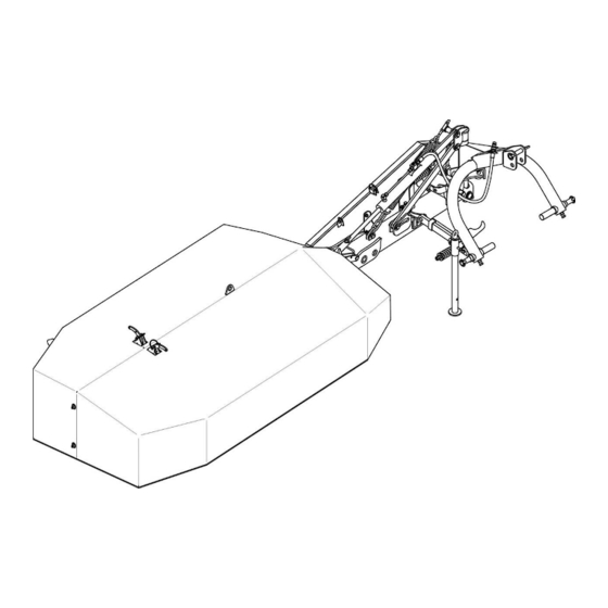
SECTION 3 PRONAR PDK220 3.2 GENERAL DESIGN FIGURE 3.1 General design (1) - linkage; (2) - cutting unit; (3) - support frame; (4) - hydraulic cylinder; (5) - drive transmission; (6) - swath guide; (7) - tarpaulin shields; (8) - safety device; (9) - support;... -
Page 36: Linkage
(5) - central connection pin; (6) - beam rotation lock pin; The main component of the linkage (FIGURE 3.2) of mower PDK220 is the three-point linkage frame (1), fitted with two adjustable pins of lower links (4) and a central connection pin (5) used for attachment to the tractor three-point linkage. -
Page 37: Drive Transmission
SECTION 3 PRONAR PDK220 3.4 DRIVE TRANSMISSION FIGURE 3.3 Drive transmission (1) - PTO shaft; (2) - drive shaft; (3) - pulleys; (4) - V-belts; (5) - tensioner Drive is transmitted from the power take-off shaft (PTO) of the tractor through the PTO shaft (1) with backstop clutch to drive shaft (2). -
Page 38: Cutting Unit
(1) - cutter bar; (2) - intersecting axis gear;(3) - cutting disc; (4) - blade; (5) - blade holder The cutting unit of mower PDK220 is composed of cutter bar (1) on which is mounted intersecting axis gear (2). On the cutter bar are mounted five cutting discs (3). On each disc are seated two rotating cutting blades (4) to right or left depending on the rotation direction of the disc. -
Page 39: Correct Use
SECTION CORRECT USE... -
Page 40: Prepare For Work
PRONAR PDK220 SECTION 4 4.1 PREPARE FOR WORK The manufacturer guarantees that the machine is fully operational and has been checked according to quality control procedures and is ready for use. This does not release the user from an obligation to check the machine's condition after delivery and before first use. The machine is delivered to the user completely assembled. - Page 41 SECTION 4 PRONAR PDK220 • operate PTO drive at low engine RPM. Engage mower's drive for a few minutes and in the meantime check the following: • that there is no knocking or noise in the drive system arising from scraping or grinding of metal elements, •...
-
Page 42: Checking Technical Condition
PRONAR PDK220 SECTION 4 4.2 CHECKING TECHNICAL CONDITION When preparing the mower for normal use, check individual elements according to guidelines presented in table (4.1). TABLE 4.1 TECHNICAL INSPECTION SCHEDULE FREQUENCY DESCRIPTION SERVICE OPERATION INSPECTIONS Check technical condition of safety... -
Page 43: Hitching To Tractor
SECTION 4 PRONAR PDK220 4.3 HITCHING TO TRACTOR PRONAR PDK220 mower may only be mounted on a tractor fulfilling the requirements contained in table „1.1 AGRICULTURAL TRACTOR'S REQUIREMENTS”. ATTENTION! Before using the mower, the user must carefully read the tractor operator's manual. - Page 44 PRONAR PDK220 SECTION 4 In order to attach the mower to tractor (FIGURE 4.1), proceed as follows: • Reversing the tractor bring the lower three point linkage connection points (A) of the tractor close to pins (1) of the mower.
- Page 45 SECTION 4 PRONAR PDK220 FIGURE 4.2 Adjustment of lower pins of the mower's linkage (1) - lower linkage pins; (2) - setting screw; (3) - counter nut, (A), (B), (C) - setting pins in arm Lower pins (1) of the mower linkage enable spacing adjustment (FIGURE 4.2). To change spacing of linkage pins: •...
-
Page 46: Transporting The Machine
SECTION 4 The method of adjustment of right and left pins is identical. As standard PRONAR PDK220 mower is equipped with pins for linking with category II linkage according to ISO 730-1. Use appropriate pins (optional equipment) or adapter balls for linking with category III or I linkage. - Page 47 SECTION 4 PRONAR PDK220 FIGURE 4.3 Transport position (A), (B), (C)- transport positions To set the mower in (C) position: • Lift the mower on three-point linkage • release and take out securing pin (2), from safety catch (FIGURE 4.5) •...
- Page 48 PRONAR PDK220 SECTION 4 FIGURE 4.4 Setting transport position (1) - lifting arm catch, (2) - cylinder valve FIGURE 4.5 Disassembly of safety device (1) - safety device; (2) - pin; (3) - cotter pin 4.10...
-
Page 49: Setting And Mowing
SECTION 4 PRONAR PDK220 To disassemble the safety device (1) from the lifting arm, remove the cotter pin (3) and pin (2), lift the safety device (1) and mount it in the linkage. The safety device is dismounted in order to set the mower to the transport position (A, C FIGURE 4.4). - Page 50 PRONAR PDK220 SECTION 4 FIGURE 4.7 Assembly of safety device (1) - safety device; (2) - pin; (3) - cotter pin To lock lifting arm in working position, assemble safety device (FIGURE 4.7). To this end, remove cotter pin (3) and, holding safety device (1), remove pin (2). Lower safety device (1) and attach to lifting arm using pin (2) with cotter pin (3).
- Page 51 SECTION 4 PRONAR PDK220 FIGURE 4.8 Setting mower in working position (1)- cylinder valve ;(2)- catch; (3)- catch cord; FIGURE 4.9 Unlocking of ground surface tracking (A) - ground surface tracking locked (parking position); (B) - ground surface tracking unlocked...
-
Page 52: Setting Cutting Height
PRONAR PDK220 SECTION 4 If ground surface tracking has been locked (A) (e.g. mower in parking position, disconnected from carrying vehicle), unlock mower lifting arm (B), prior to operation of mower, by removing cotter pin from hole in bar and install it in sleeve (FIGURE 4.9). -
Page 53: Connecting Of Pto Shaft
SECTION 4 PRONAR PDK220 FIGURE 4.11 Setting cutting height (1) - cutter bar; (2) - top link (central link); (B) - cutter bar inclination of 4º÷5º against ground Adjust length of top link (2) so that cutter bar inclination angle (B) (in the mowing direction) -
Page 54: Adjustment Of Stay Spring
(except for maintenance and repairs, transport travel or extended periods of machine parking). The PTO shaft of the PDK220 mower is equipped with a backstop clutch, which is at the end of the shaft from the side of the mower. -
Page 55: Mowing
SECTION 4 PRONAR PDK220 4.5.5 MOWING DANGER The mower may only be started when all guards are in place and the cutting unit is set in working position. Before engaging drive to PTO shaft make sure that there are no bystanders, especially children, near the mower. -
Page 56: Safety Device
Do NOT operate mower while reversing. While reversing raise the cutting unit. 4.5.6 SAFETY DEVICE The PDK220 mower is equipped with a safety device, which protects the machine against damage resulting from collision with obstacles (FIGURE 4.14). When driving over an obstacle, the lifting arm with the cutting unit tilts backwards (C). - Page 57 SECTION 4 PRONAR PDK220 FIGURE 4.14 Fuse (1) - safety device; (2) - tensioning nut; (3) - safety device spring (A) - factory spring setting A=132 mm; (B) - working position; (C) - safety device action ATTENTION! Excessive tension of the spring prevents action of safety device and may cause damage to machine as a result of driving over obstacle.
-
Page 58: Unhitching From Tractor
PRONAR PDK220 SECTION 4 4.6 UNHITCHING FROM TRACTOR FIGURE 4.15 Disconnecting mower from tractor (1) - support leg; (2) - support leg securing cotter pin; (3) - lifting arm lock cotter pin; (4) - hydraulic quick coupler; (5) - securing plug; (4) - quick coupler bracket; (7) - PTO shaft;... - Page 59 SECTION 4 PRONAR PDK220 DANGER Before disconnecting mower from the tractor linkage, lock bearing beam with the aid of cotter pin (3) (FIGURE 4.15). Do NOT disconnect mower from tractor without locking the beam. In order to disconnect the mower from the tractor (FIGURE 4.15) proceed as follows: •...
- Page 60 PRONAR PDK220 SECTION 4 4.22...
-
Page 61: Maintenance
SECTION MAINTENANCE... -
Page 62: Checking And Replacing Cutting Blades
PRONAR PDK220 SECTION 5 5.1 CHECKING AND REPLACING CUTTING BLADES DANGER During inspection and replacement of blades, turn off tractor engine and remove the key from the ignition and disengage PTO shaft. Cutter bar must rest on the ground. FIGURE 5.1 Replacement of cutting blades (1)- cutting blade;... - Page 63 Use only CE certified blades meeting the requirements of ISO 5718 standard. ATTENTION! Missing blade or its fragment will cause imbalance and excessive cutting disk vibration and may damage the cutter bar. TABLE 5.1 Cutting blade characteristics for PDK220 mower DESIGNATION DIMENSIONS DIRECTION QUANTITY...
- Page 64 PRONAR PDK220 SECTION 5 Damaged or worn blades must be changed in pairs in order to maintain balance of cutting disc. FIGURE 5.2 Blade types depending on cutting disc rotation direction (A) - right blades; (B) - left blades Due to different cutting disc rotation direction, cutter bar (FIGURE 5.2) is equipped with the right blades (A) and left blades (B).
-
Page 65: Cutting Unit Service
SECTION 5 PRONAR PDK220 5.2 CUTTING UNIT SERVICE Service of cutting unit involves periodic inspection and change of oil in cutter bar and in intersecting axis gear. FIGURE 5.3 Checking and change oil in cutter bar (1)- inspection filler plug; (2)- drain plug; (A)- correct oil level in cutter bar 6÷8 mm from bottom of bar Correct oil level (A) with cutter bar in horizontal position is 6 ÷... - Page 66 PRONAR PDK220 SECTION 5 First oil change should be made after 50 hours mower operation and then, after each 500 hours of operation or at least once in the season, whichever occurs first. 2.4 litres of SAE90EP (80W90 GL5) gear oil can be poured into cutter bar. It is best to change oil immediately after completing work when cutter bar is still hot and impurities are suspended in oil.
- Page 67 SECTION 5 PRONAR PDK220 To check the oil level in intersecting axis gear: • set cutter bar horizontally, • unscrew inspection plug (1) (FIGURE 5.4), • oil level should reach the lower edge of the plug opening (1), • if necessary, supplement oil to the required level.
- Page 68 PRONAR PDK220 SECTION 5 FIGURE 5.4 Checking and change of oil in intersecting axis gear (1) - inspection plug (2) - filler plug with air vent, (3) - drain plug (A) - correct oil level To lubricate intersecting axis gear, use transmission oil SAE90EP (80W90 GL-5).
-
Page 69: Operation Of Drive Transmission
SECTION 5 PRONAR PDK220 5.3 OPERATION OF DRIVE TRANSMISSION DANGER Before proceeding to check or adjust tension of drive transmission belt set first turn off tractor engine and remove key from ignition. Drive transmission system maintenance consists of periodic inspection, regulation and possible change of vee belts. - Page 70 PRONAR PDK220 SECTION 5 FIGURE 5.5 Check and adjust tension of vee belts (2) - tensioning spring; (2) - tensioner nut; (3) - inspection opening; (4) - guard fixing nuts; (5) - vee belts; (6) - belt guard (A) - maximum deflection of belt in inspection opening A=30 mm, Inspect vee belts in the drive transmission periodically during the use of the machine.
-
Page 71: Hydraulic System Operation
SECTION 5 PRONAR PDK220 5.4 HYDRAULIC SYSTEM OPERATION The duties of the operator connected with the hydraulic system include: • visual inspection of hydraulic connection tightness, • checking technical condition of lines, • visual inspection of hydraulic quick coupler. DANGER Do not repair hydraulic system on your own. - Page 72 PRONAR PDK220 SECTION 5 In the event of confirmation of an oil leak on hydraulic conduit connections, tighten connections, and if this does not remedy faults then change conduit or connection elements. Change of sub-assemblies is equally required in each instance of mechanical damage.
-
Page 73: Storage
SECTION 5 PRONAR PDK220 5.5 STORAGE After finishing work, the mower should be thoroughly cleaned. Do NOT direct water jets directly onto hydraulic system components, lubrication points or information and warning decals. High water jet pressure may damage these elements. -
Page 74: Lubrication
PRONAR PDK220 SECTION 5 5.6 LUBRICATION Machine lubrication should be performed with the aid of a manually or foot operated grease gun, filled with generally available permanent grease. Before commencing lubrication insofar as is possible remove old grease and other contamination. Remove and wipe off excess oil... - Page 75 SECTION 5 PRONAR PDK220 FIGURE 5.6 Lubrication points Lubrication points described in table 5.3 5.15...
-
Page 76: Tightening Torque For Nut And Bolt Connections
PRONAR PDK220 SECTION 5 5.7 TIGHTENING TORQUE FOR NUT AND BOLT CONNECTIONS Unless other tightening parameters are given, during maintenance repair work apply appropriate torque to tightening nut and bolt connections. Recommended torque values apply to non-greased steel bolts. ATTENTION! Should it be necessary to change individual parts, use only original parts or those indicated by the Manufacturer. -
Page 77: Troubleshooting
SECTION 5 PRONAR PDK220 5.8 TROUBLESHOOTING TABLE 5.5 TROUBLESHOOTING TYPE OF FAULT CAUSE REMEDY Lifting arm interlocked Remove blocking pin Incorrectly connected or Check quick couplers and Mower arm cannot be damaged quick coupler manner of their connection lifted or lowered... - Page 78 PRONAR PDK220 SECTION 5 5.18...
- Page 79 NOTES ………………………………………………………………………………………………………………………………….. ………………………………………………………………………………………………………………………………….. ………………………………………………………………………………………………………………………………….. ………………………………………………………………………………………………………………………………….. ………………………………………………………………………………………………………………………………….. ………………………………………………………………………………………………………………………………….. ………………………………………………………………………………………………………………………………….. ………………………………………………………………………………………………………………………………….. ………………………………………………………………………………………………………………………………….. ………………………………………………………………………………………………………………………………….. ………………………………………………………………………………………………………………………………….. ………………………………………………………………………………………………………………………………….. ………………………………………………………………………………………………………………………………….. ………………………………………………………………………………………………………………………………….. ………………………………………………………………………………………………………………………………….. ………………………………………………………………………………………………………………………………….. ………………………………………………………………………………………………………………………………….. ………………………………………………………………………………………………………………………………….. ………………………………………………………………………………………………………………………………….. ………………………………………………………………………………………………………………………………….. ………………………………………………………………………………………………………………………………….. ………………………………………………………………………………………………………………………………….. ………………………………………………………………………………………………………………………………….. ………………………………………………………………………………………………………………………………….. ………………………………………………………………………………………………………………………………….. ………………………………………………………………………………………………………………………………….. ………………………………………………………………………………………………………………………………….. …………………………………………………………………………………………………………………………………..
Need help?
Do you have a question about the PDK220 and is the answer not in the manual?
Questions and answers