Table of Contents
Advertisement
Quick Links
PRONAR Sp. z o.o.
TRANSLATION OF THE ORIGINAL COPY OF THE MANUAL
EDITION: 1A.10.2019
17-210 NAREW, UL. MICKIEWICZA 101A, PODLASKIE PROVINCE, POLAND
PHONE: +48 085 681 63 29
+48 085 681 63 81
FAX:
+48 085 681 63 83
OPERATOR'S MANUAL
MULCHING MOWER
KPR500 TORNADO
KEEP FOR FUTURE REFERENCE
+48 085 681 64 29
+48 085 681 63 82
+48 085 682 71 10
www.pronar.pl
PUBLICATION NO.: 586.00.UM
EN
Advertisement
Table of Contents

Related Manuals for PRONAR KPR500 TORNADO


Summary of Contents for PRONAR KPR500 TORNADO
- Page 1 PRONAR Sp. z o.o. 17-210 NAREW, UL. MICKIEWICZA 101A, PODLASKIE PROVINCE, POLAND PHONE: +48 085 681 63 29 +48 085 681 64 29 +48 085 681 63 81 +48 085 681 63 82 FAX: +48 085 681 63 83 +48 085 682 71 10 www.pronar.pl...
- Page 3 INTRODUCTION...
- Page 4 Before are inscribed in the spaces below after using the machine, the user must carefully purchase of the machine. read this Operator's Manual and observe Machine serial number U.01.1.EN PRONAR KPR 500...
-
Page 5: Introduction
TIP. In order to focus the user's attention on the need to perform maintenance, the rel- evant section of the Operator's Manual is marked with the clock pictogram. U.02.1.EN PRONAR KPR 500... -
Page 6: Directions Used In This Operator's Manual
(the operator is chine's forward travel. facing the mechanism). U.03.1.EN 586-B.01.1 Figure 1.1 Directions used with reference to the machine (A) front , (B ) rear, (C) left side, (D) right side PRONAR KPR 500... -
Page 9: Table Of Contents
Safety during machine operation Safe operation of the PTO shaft 2.10 Residual risk 2.11 Information and warning decals 2.12 DESIGN AND OPERATION Technical specification Design and operation Linkage Hydraulic system Electrical system Drive transmission. Additional and optional equipment 3.10 PRONAR KPR 500... - Page 10 CORRECT USE Get ready for operation Technical inspection Hitch the mower to implement carrier (tractor). Operate the mower Driving on public roads 4.12 Unhitching the machine from the carrier vehicle 4.13 MAINTENANCE Half axle maintenance Wheel maintenance Hydraulic system maintenance Drive transmission system maintenance Cutting unit maintenance 5.12...
-
Page 11: Basic Information
BASIC INFORMATION... -
Page 12: Identification
Section 1 Basic information 1.1 IDENTIFICATION The PRONAR KPR 500 TORNADO mulching mower has been marked with PRONAR Sp. z o.o. 17-210 Narew a rating plate located on the mower's frame ul. Mickiewicza 101A PRONAR Nazwa (1.1). When buying the machine check... -
Page 13: Intended Use
Basic information Section 1 1.2 INTENDED USE The PRONAR KPR 500 TORNADO IMPORTANT mulching mower is designed to operate on The machine must not be used for purposes other large areas. Use the machine to: than those for which it is intended, in particular for: transport people, animals or any items on the ma- •... - Page 14 16 (160) in the hydraulic system (bar) Hydraulic sockets: 12.5 ISO 7241-1 Type A sockets 1 single acting section 1 single acting section with floating position Electric sockets 7-pin socket, 12V (power supply of rear lamp assembly) E.1.1.586.02.1.EN PRONAR KPR 500...
-
Page 15: Equipment
1.3 EQUIPMENT • Operator’s Manual • Connection lead for the electrical system • Warranty Book • PTO shaft for connection of the Recommended PTO shaft for connection with tractor: B&P 7G7R111CEWR7A53X mower with tractor • Wheel chocks; E.1.1.586.03.1.EN PRONAR KPR 500... -
Page 16: Terms & Conditions Of Warranty
Section 1 Basic information 1.4 TERMS & CONDITIONS OF WARRANTY PRONAR Sp. z o.o. Narew guarantees the • use of damaged machine, • repairs carried out by unauthorised reliable operation of the machine when it is used according to its intended purpose... -
Page 17: Shipping
This is due to the vehicle's centre of gravity shifting upwards when the machine is loaded. machine connected to carrier vehicle is permissible provided that the driver famil- iarises himself with the Operator's Manual 1065 586-E.01-1 Figure 1.2 Machine’s centre of gravity PRONAR KPR 500... - Page 18 1.3). chine. During the loading work particular The KPR500 mower should be firmly se- care should be taken not to damage paint cured on the transportation platform with coating. belts or chains equipped with a tensioning E.1.1.586.05.1.EN PRONAR KPR 500...
-
Page 19: Envoronmental Risk
The The hydraulic system of the mower is filled with container should be kept away from heat L-HL32 Lotos hydraulic oil. sources, flammable materials and food. E.1.1.586.06.1.EN PRONAR KPR 500... -
Page 20: Withdrawal From Use
(overhead crane, crane or hoist etc.) and use oil are described in Section 5. personal protection equipment, i.e. protective cloth- ing, footwear, gloves and eye protection etc. When spare parts are changed, worn out E.1.1.586.07.1.EN PRONAR KPR 500 1.10... -
Page 21: Safety Advice
SAFETY ADVICE... -
Page 22: Safe Use
(agricul- tures, they must be replaced with tural tractors), including children and new ones. people under the influence of alcohol F.1.1.586.01.1.EN PRONAR KPR 500... -
Page 23: Safety When Hitching The Machine
• The carrier vehicle (agricultural connect it again. tractor) to which the machine will be F.1.1.586.02.1.EN PRONAR KPR 500... -
Page 24: Safety Rules When Maintaining Hydraulic System
• In the event of injuries being caused • Repair and replacement of hydraulic by pressurised hydraulic oil, contact system elements should be entrusted a doctor immediately. Hydraulic oil to the appropriately qualified persons. F.1.1.586.03.1.EN PRONAR KPR 500... -
Page 25: Safety During Transport Travel
• Do not exceed the maximum speed hitch system and elements con- resulting from road conditions and necting the hydraulic system. design restrictions (maximum of 20 • Reckless driving excessive km/h). Adjust your speed to the road speed may cause accidents. conditions. F.1.1.586.04.1.EN PRONAR KPR 500... -
Page 26: Maintenance And Cleaning
• Regularly perform service inspec- also damage the machine and inval- tions of machine as recommended by idate the warranty. the Manufacturer. • Regularly check technical condition PRONAR KPR 500... - Page 27 In the event of doubt gressively with the mobile stockpiler's it is recommended to make a test on structural elements. an unseen surface area. • The use of a pressure washer • Surfaces smeared with oil or grease PRONAR KPR 500...
- Page 28 • Washing and drying the machine must instructions. • Washing detergent should be kept take place at temperature above 0°C. in original containers, optionally in • Each time after washing lubricate the replacement containers, but very machine. clearly marked. Preparations may not F.1.1.586.05.1.EN PRONAR KPR 500...
-
Page 29: Safety During Machine Operation
Damaged or incomplete sub-assem- • Do NOT approach the machine until blies must be exchanged for original the rotating parts come to a complete new ones. stop. F.1.1.586.06.1.EN PRONAR KPR 500... -
Page 30: Safe Operation Of The Pto Shaft
• Do NOT go over and under the shaft cover from turning while the shaft is or stand on it equally during work as working, shall be secured to a fixed also when the machine is parked. element of machine structure. F.1.1.586.07.1.EN PRONAR KPR 500 2.10... -
Page 31: Residual Risk
Safety advice Section 2 2.8 RESIDUAL RISK Pronar Sp. z o. o. in Narew has made checks when carrier vehicle (agricul- tural tractor) is connected and engine every effort to eliminate the risk of acci- dents. There is, however, a certain residual is running. -
Page 32: Information And Warning Decals
If any are destroyed or damaged, they must be replaced with water jets. 10 12 586-E.09.1 Figure 2.1 Locations of information and warning decals. PRONAR KPR 500 2.12... - Page 33 Before beginning servicing or repairs, turn off tractor engine and remove key from ignition. 185N-00000002 Pulling the whole body - Drive train 185N-00000003 Crushing the entire body - force applied from above Crushing - the mower wing 185N-00000007 PRONAR KPR 500 2.13...
- Page 34 586N-05000003 Pressurised liquid jet. Keep a safe distance. 586N-05000004 Cutting height X mm 586N-05000005 25 mm 75 mm 140 mm 200 mm 260 mm 1-10 320 mm 1-12 380 mm 400 mm PRONAR KPR 500 2.14...
- Page 35 Safety advice Section 2 Item Decal Meaning Mower position 586N-05000006 Machine type PRONAR KPR500 TORNADO 586N-05000007 F.1.1.586.09.1.EN PRONAR KPR 500 2.15...
- Page 36 Section 2 Safety advice PRONAR KPR 500 2.16...
-
Page 37: Design And Operation
DESIGN AND OPERATION... - Page 38 The rear of the mower is sus- Linkage pended on wheels, the front rests on the tractor hitch. PTO maximum speed 1000 Operating speed km/h (5 – 20)* km/h Permissible design transport speed ** Nominal pressure in the system 16 (160) hydraulic system (bar) PRONAR KPR500...
- Page 39 Emitted sound pressure rpm) Other information single person operation *) - operating speed should be adapted to the type and amount of ground material and the terrain **) - the permissible transport speed is determined by local traffic regulations G.1.1.586.01.1.EN PRONAR KPR500...
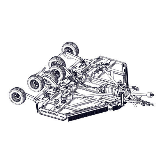
- Page 40 (3) left wing (4) parking stand (5) lower drawbar (6) PTO shaft (7) chain guard (8) wing skid (9) centre plate skid (10) linkage (11) hydraulic system (12) wing cylinder (13) drive transmission (14 rear lighting (15) cutting unit PRONAR KPR500...
- Page 41 There is a drive system (10) at the rear of indicators). the mower. The drive system consists of a frame, control rods and half axle shafts The standard equipment includes an artic- with wheels. The height of the mower's ulated PTO shaft (6). G.1.1.586.02.1.EN PRONAR KPR500...
-
Page 42: Linkage
Section 3 Design and operation 3.3 LINKAGE 586-G.06.1 Figure 3.2 Linkage design (1) lower drawbar (2) suspension rod (3) suspension cylinder (4) centre plate linkage frame (5) rear wheel suspension side frame G.1.1.586.03.1.EN PRONAR KPR500... -
Page 43: Hydraulic System
.1 - absorber version, v.2 - standard version (1) suspension cylinder (2) wing cylinder (3) suspension cylinder valve (4) wing cylinder valve (5) flow divider (6) six-way manifold (7) hydraulic accumulator assembly (8) cut-off valve (9) hydraulic coupler plugs G.1.1.586.04.1.EN PRONAR KPR500... -
Page 44: Electrical System
Design and operation 3.5 ELECTRICAL SYSTEM 586-G.03.1 Figure 3.4 Rear lights electrical system design (1) coiled cable 7- pin 12V electric plug, (2) 7 pin electrical plug (3) central wiring harness (4) front wiring harness (5) rear lamps G.1.1.586.05.1.EN PRONAR KPR500... -
Page 45: Drive Transmission
Bevel gears rotate the cutting units articulated shaft (1) to the main divider gearbox (2). From the gearbox (2), the with blades. The cutting units should rotate as indicated on the figure. drive is divided into bevel gears (5,6,7) of G.1.1.586.06.1.EN PRONAR KPR500... -
Page 46: Additional And Optional Equipment
(5) using the tie rod (4). wheels. To do this: • set the mower on an even surface • repeat the steps for the other the in the unfolded position (Figure 3.6), wheel, PRONAR KPR500 3.10... - Page 47 586-G.09.1 Figure 3.7 Front gauge wheels (1) gauge wheel (2) securing lugs (3) mower wing (4) suspension rod (5) rear wheel suspension side frame (6) centre suspension frame G.1.1.586.07.1.EN PRONAR KPR500 3.11...
- Page 48 Section 3 Design and operation PRONAR KPR500 3.12...
-
Page 49: Correct Use
CORRECT USE... -
Page 50: Get Ready For Operation
- see the DANGER manufacturer's operating manual), Before starting the machine, ensure that there are no • check the compatibility and technical bystanders in the danger zone. condition of the hydraulic and electric PRONAR KPR500... - Page 51 If a fault connected to carrier vehicle, started and cannot be rectified or the repair could void all its individual systems checked. In order the warranty, please contact the Manufac- to do this: turer for additional clarifications. H.1.1.586.01.1.EN PRONAR KPR500...
-
Page 52: Technical Inspection
“Drive transmission system hours Change oil in gears maintenance.” once a year, depending on which comes earlier Check if all main nut and bolt Tightening torque should be according Every six months connections are properly tight- to table (5.7) ened PRONAR KPR500... - Page 53 Checking axle shaft bearings for In accordance with the chapter “Check Every six months slackness wheel half axle bearings for loose- ness.” Lubrication Lubricate elements according to guide- According to lines presented in section "Lubrication". table (5.5) E.1.1.586.02.1.EN PRONAR KPR500...
-
Page 54: Hitch The Mower To Implement Carrier (Tractor)
The proper alignment of the PTO shaft of the imple- ment carrier (tractor) with the shaft of the machine's Use only genuine pins and safeguards to hitch the drive system significantly extends the life of the drive machine to the carrier vehicle. shaft. PRONAR KPR500... - Page 55 DANGER Before connecting to the carrier vehicle, check tech- nical condition of shaft guards as well as complete- Exercise due caution during folding support - danger ness and condition of protecting chains. of severing limbs. PRONAR KPR500...
- Page 56 (3) of the Only transport the mower with the telescopic shaft disconnected. mower with the locking strips (4). The machine is ready for transport. 586-H.03.1 Figure 4.3 Correct direction of rotation of the cutting unit E.1.1.586.03.1.EN PRONAR KPR500...
-
Page 57: Operate The Mower
(tractor) PTO, check the rotation During operation people and animals mut not be present within a 100 m radius of the machine. direction of the cutting units (Figure 4.3). Operation from the tractor only. The cutting units should rotate according PRONAR KPR500... - Page 58 • Inspect and remove remaining debris when driving forward. Do not mow when • cut at the target height. -25º +30º 586-H.07.1 Figure 4.5 Mower operation on a slope - ground contour following PRONAR KPR500 4.10...
- Page 59 • The mowing area has been checked chanical locks (figure 4.2) and foreign objects and they have • Set the suspension hydraulic valves been removed. in a closed position, • There are no bystanders nearby • Clean the machine of plant residue. H.1.1.586.04.1.EN PRONAR KPR500 4.11...
-
Page 60: Driving On Public Roads
• Avoid ruts, depressions, ditches or H.1.1.586.05.1.EN PRONAR KPR500 4.12... -
Page 61: Unhitching The Machine From The Carrier Vehicle
• Put the machine in a parking place. • Unlock the suspension cylinder from PTO, transport position (Figure 4.2), and • After disconnecting the articulated tel- lower the suspension as much as escopic shaft, place it on the support possible, H.1.1.586.06.1.EN PRONAR KPR500 4.13... - Page 62 Section 4 Correct use PRONAR KPR500 4.14...
-
Page 63: Maintenance
MAINTENANCE... -
Page 64: Half Axle Maintenance
Ensure that machine will not Procedures connected with: move during inspection. • changing grease in half axle bearings, • Raise the wheel (opposite to the side • changing bearings, hub seals, where chocks are placed). Lifting PRONAR KPR500... - Page 65 Bearing life is dependent on machine working con- scription provided in the section PREPA- ditions, loading, ground speed and lubrication con- RATION PROCEDURE. ditions. Adjusting looseness of half axle bearing PRONAR KPR500...
- Page 66 The wheel should turn smoothly without jamming and detectable resistance. Only • Take off hub cover (1) – figure (5.2). • take out split cotter pin (2) securing adjust bearings, when the machine is hitched to a tractor. castellated nut (3) I.1.1.586.01.1.EN PRONAR KPR500...
-
Page 67: Wheel Maintenance
TIGHTENING NUTS warm, or after the machine has been Nuts should be tightened gradually diago- parked for an extended period. nally, (in several stages, until obtaining the While checking pressure pay attention to PRONAR KPR500... - Page 68 DANGER the tyre defect requires tyre replacement. Damaged tyres or wheels may be the cause of a se- Wheels should be inspected with regard to rious accident. distortion, breaking of material, breaking I.1.1.586.02.1.EN PRONAR KPR500...
-
Page 69: Hydraulic System Maintenance
Hydraulic oil in normal condi- Minimum leaks are permissible with tions is not harmful to the respiratory tract. symptoms of "sweating", however in A hazard only occurs when oil is strongly the event of noticing leaks in the form of PRONAR KPR500... - Page 70 10 (3/8”) 50÷70 M22x1,5 | M24x1,5 | M26x1,5 13 (1/2”) 50÷70 M26x1,5 | M27x1,5 | M27x2 16 (5/8”) 70÷100 M30x1,5 | M30x2 | M33x1,5 20 (3/4”) 70÷100 M38x1.5 | M36x2 25 (1”) 100÷150 M45x1.5 32 (1.1/4”) 150÷200 I.1.1.586.03.1.EN PRONAR KPR500...
-
Page 71: Drive Transmission System Maintenance
The shafts are equipped with friction clutches, which can become hot during slipping. Add oil through the filler opening in the gear top cover. 586-I.05.1 Figure 5.4 Inspect and replace oil in the gearbox (1) bevel gear (2) divider gearbox (3) telescopic shafts PRONAR KPR500... - Page 72 (4) inspection opening cover divider gear (5) blade mounting nut (7) cutting unit mounting (1) gear body (2) plug with dipstick; (8) cutting unit guard (9) cutting blades (10) cutting unit (3) oil drain bracket (11) inspection opening PRONAR KPR500 5.10...
- Page 73 • tighten drain plug (3). To change oil in bevel gearbox (Figure • assemble the cutting unit, 5.4): • add oil to the gear. • unscrew the inspection hole cover I.1.1.586.04.1.EN PRONAR KPR500 5.11...
-
Page 74: Cutting Unit Maintenance
• remove the blades from the sockets, remove the sleeves (7) from the blade opening, IMPORTANT There is no need to remove the cutting unit guard for When installing the blades, note the cutting unit ro- blade maintenance. tation direction. PRONAR KPR500 5.12... - Page 75 Bolt and nut connection should be order using new nuts. tightened using proper tightening torque. Table 5.3. List of wearing parts Item Name Part No. Quantity Left blade 303-890-000250 3 pcs Right blade 303-890-000249 6 pcs I.1.1.586.05.1.EN PRONAR KPR500 5.13...
-
Page 76: Electrical System Maintenance
Burned-out or damaged lamps must be replaced with new ones. 586-I.04.1 Figure 5.8 Electrical system diagram (1) - 7-pin 7P / 12V socket ; (2) centre harness (3) rear harness (4) rear lamps I.1.1.586.06.1.EN PRONAR KPR500 5.14... -
Page 77: Lubrication
Lubricate the machine when it is lowered on its sup- ports and resting on the ground. Before lubricating, turn off engine, remove key from ignition and engage carrier vehicle brake. Table 5.4. Lubrication points and lubrication frequency Name Drawbar eye 586-I.06.1 PRONAR KPR500 5.15... - Page 78 Section 5 Maintenance Hitch pins (front) 586-I.07.1 Hitch pins (rear) 586-I.08.1 PTO shaft (socket) 586-I.09.1 tooltip Wing cylinder bolts 586-I.10.1 PRONAR KPR500 5.16...
- Page 79 Maintenance Section 5 Suspension cylinder pins 586-I.11.1 Suspension locking pin 586-I.12.1 Wing hinge 586-I.13.1 Suspension rods 586-I.14.1 PRONAR KPR500 5.17...
- Page 80 Section 5 Maintenance Rocker arm pin 586-I.15.1 Shaft elbows* 586-I.16.1 Bevel gear divider gearbox 586-I.17.1 Hub bearings (2 bearings in each hub) 586-I.18.1 PRONAR KPR500 5.18...
- Page 81 SAE 90EP (80W90 GL-5) transmission oil . Lubrication frequency (see table Machine lubri- cation schedule): D - working day (8 hours of machine use) M - month I.1.1.586.07.1.EN PRONAR KPR500 5.19...
-
Page 82: Tighten Bolt Connections
569-I.09-1 Figure 5.9 Bolt with metric thread (1) resistance class (d) thread diameter Table 5.6. Tightening torque for nut and bolt connections 10.9 THREAD MARKING [mm] TIGHTENING TORQUE [Nm] 1,050 1,150 1,650 1,450 2,100 1,450 2,100 I.2.5.28.06.1.EN PRONAR KPR500 5.20... -
Page 83: Storage
I.1.1.586.09.1.EN PRONAR KPR500 5.21... -
Page 84: Troubleshooting
Clutch linings heavily worn or Repair the clutch according to the clutch slips warped plates. shaft manual. Excessive shaft load. Reduce ground speed and material intake. Oil on linings. Replace the linings. Glazed friction linings. Wipe with sandpaper. PRONAR KPR500 5.22... - Page 85 (See @Operation section - Adjust the mower height - Adjust level) Reduce ground speed. Cut too high. Lower cutting height. (See “Operating section - Set up the mower - Set the deck height”) I.1.1.586.10.1.EN PRONAR KPR500 5.23...
- Page 86 Section 5 Maintenance PRONAR KPR500 5.24...
Need help?
Do you have a question about the KPR500 TORNADO and is the answer not in the manual?
Questions and answers