
Related Manuals for Hisense HAIO136


Summary of Contents for Hisense HAIO136
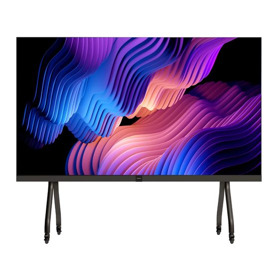
- Page 1 HAIO136 Read the manual carefully and ensure you have fully understood its contents before operating this device for the first time. English RSAG2.025.8671SS C...
- Page 2 Safety Precautions Declaration Any content and service accessed through this device shall be the property of the applicable third party and subject to protection by regulations and laws on copyright, patent, trademark and other intellectual property rights. No part of such content and service may be modified, duplicated, published, uploaded, distributed,translated, marketed, or used to make and distribute products derived from it without the prior permission of the content owner or service provider.
- Page 3 This symbol alerts user about the presence ATTENTION of a dangerous voltage not isolated inside the RISK OF SHOCK product which can be sufficiently powerful to ELECTRIC constitute a risk of electrocution. Do not open the back cover. In no case the user is allowed to operate inside This symbol alerts user about the presence of important operating instructions and the device.
- Page 4 Safeguards Please read the following safeguards for your device and retain for future reference. Always follow all warnings and instructions marked on the device. 1. A note about safety and operating instructions Read and follow all safety and operating instructions, and retain them safely for future reference. 2.
- Page 5 (d) If the device does not operate normally by following the operating instructions. Adjust only that are covered by the operating instructions as an improper adjustment of other controls may result in damage and will often require extensive work by a qualified technician to restore the device to its normal operation. (e) If the device has been dropped or the cabinet has been damaged.
-
Page 6: Table Of Contents
CONTENTS Accessories List..............................1 Remote Control ..............................2 Front Panel & Interface...........................4 Making Connections ............................5 Initial Start...............................8 Use of Menu ..............................12 Serial Protocol ..............................19 Other Infomation ............................20 Trouble Shooting ............................21 Other Infomation ............................23 Installation Guideline ...........................25 Accessories List Remote Control × 1 Battery ×... -
Page 7: Remote Control
Remote Control Number Description Power Enter/exit standby Source Switching signal source Move focus up/down < / > Move focus left/right Back Back to previous menu Volume down (-) Mute Activate/exit mute state Setting Open the Settings menu Blank Switch On/Off screen Confirm operation Freeze once click: Keep the current screen... - Page 8 Battery replacement method Disconnect the battery cover from the remote control at the battery cover buckle and open the battery cover. Insert two AAA 1.5V alkaline batteries. Note that the positive (+) and negative (-) terminals of the batteries must match the positive (+) and negative (-) terminals in the battery case. Close the battery cover from top to bottom until it is fully aligned with the remote control.
-
Page 9: Front Panel & Interface
Front Panel & Interface Standby/IR Power Cord Item Description When the device is on, short press the button to turn off the screen, long press the button to go into standby mode. When the screen is off, press the button to open the screen, and when the device is on standby, press the button to start. -
Page 10: Making Connections
Making Connections Connect to USB interface device The total current of all the USB output ports of the device when connected to external devices at the same time mustn’t exceed 1000mA, or else the device failure caused by overcurrent isn’t covered by the warranty. - Page 11 Connect to network Enter the Settings menu and select the Network item. WIFI Wireless router Network port Network port in the wall The device can receive network signals directly through Wireless router • The available wireless network list is automatically displayed when the WIFI is selected. •...
- Page 12 • Switching on/off the OPS After inserting OPS to the device, you turn on the device, change the signal source to enter OPS and stays on the OPS syetem interface. When you turn off the device, you should use the standby button to go into standby mode, the OPS module is switched off, and then you shut off the device.
-
Page 13: Initial Start
Initial Start Switching on/off Connect the power cord of the device to a 100V to 240V AC outlet. Press the standby button [ ] on the remote control in the power on state to switch the device to standby; to resume normal watch, simply press the standby button [ ] on the remote control again. To turn off the device, press the power switch or Unplug the Power cord. - Page 14 • Choose the App icon to select Application and File.
- Page 15 • Hisense Screen Share • Guide for Dongle (1) Pairing Pairing method: Insert the Miracast into the USB port of the whole machine, and pair it. After successful, insert it into the USB port of computer, and automatically run Miracast software. Click Miracast button according to the prompts.
- Page 16 • Guide for Phone 1. Download method: Official website of Hisense Commercial Display or scan QR code at the large-screen terminal. This app can also be found by searching for “HisenseScreenShare” in the Google App Store and Apple App Store 2.
-
Page 17: Use Of Menu
Use of Menu Universal Inputting method: Kika Keyboard F Language setting: English Time zone setting Time and date setting DTMS DTMS startup setting: 1Min DTMS jump setting: HisenseWelcomebo Inputting method: switch the input method. The default input method is Kika. Language setting: Select menu language as Chinese/English/French/German/Spanish/Italian/ Polish/ Arabic. - Page 18 Network Wireless network: Disconnected Wired network: Disconnected Wireless hotspot: Closed Wireless display Network details Bluetooth Network diagnostics Wireless network: Switch on the wireless network, display the connection status of the wireless network and the list of available networks. You can choose to refresh or manually add networks that do not appear in the list.
- Page 19 On/Off OPS switch Timed switch on/off Boot status: Power on OPS switch:Switch on or off, and off-by-default. Timed switch on/off: Set the fixed on/off time, and it will be commenced automatically when the time is up. The clock can set hours and minutes in a 24-hour mode, and three on/off time periods can be set every day.
- Page 20 Image Image mode: Standard Smart backlight adjustment: Customization Advanced setting Reset all image setting Image mode: Select the appropriate picture effect according to the content you are watching. You can select Standard, Meeting, Cinema, Showroom, HDR Standard, HDR showroom, and Default Standard. (When playing HDR source, you can select HDR Standard and HDR showroom) Smart backlight adjustment: Featured display technology to realize independent control of screen brightness by backlight module.
- Page 21 Sound Sound Mode: Standard DTS sound effect Output device: Local Speaker Audio output format Advanced setting Megaphone mode Reset all sound setting Sound Mode: Select the appropriate sound effect according to the content you are watching. You can select Standard, Sports, Movie, Music, Customization, and Default Standard. DTS sound effect: Switch on or off DTS Bass Boost, DTS Virtual Sky Tone, DTS Clear Dialogue, DTS Loudness Adjustment, or select Reset.
- Page 22 System One-touch play HDMI version Debug mode Local key: ON HDMI control One-touch play: After switched, connect the set-top box, computer and other external devices, and the device will automatically play the device screen. You can select On or Off. HDMI version: HDMI1.4, HDMI2.0.
- Page 23 About Local information Local name Disclaimer Application management Check for updates Factory reset Local information: Display local information. Software Version, Device ID, Machine Number, and System Capacity can be selected. Local name: Select or customize the local name to facilitate the discovery of devices during Bluetooth pairing, screen projection and other operations.
-
Page 24: Serial Protocol
Serial Protocol Serial port status The device can receive the serial port command sent by the external controller or OPS of the device. Refer to the following table for the specific command protocol: 1. Baud rate: 115200 2. Control section: PC → The device 3. Response section: TV → PC Protocol Length Command code... -
Page 25: Other Infomation
Other Infomation Recycling/Licenses WEEE (Waste Electronic Electric Equipment) European Directive 2012/19/EU This symbol on the product or on its packaging indicates that this product must not be disposed of with your household waste. Instead, it is your responsibility to dispose of your waste equipment by handing it over to a designated collection point for the recycling of waste electrical and electronic equipment. -
Page 26: Trouble Shooting
Trouble Shooting Before preparing for repair, check according to the table below to see if you can find the cause of the problem. If you strictly follow the instructions but still can’t resolve the problem, you can turn to professional servicemen for help. - Page 27 4. Physical impact The LED display screen is a very delicate device. It needs protection from any kind of physical impact, as it may resulting damage to LED beads or circuit board. Maintenance of LED display screen 1. The control PC, video processor and other equipment shall be placed in a dry and clean environment with good ventilation.
-
Page 28: Other Infomation
Other Information Specification HAI0136 Pixel Pitch 1.5625 mm Pixel Configuration 3 in one SMD × × Screen Resolution (W 1,920 1,080 × × Screen Dimensions (W D) (mm) 3004×1774.5×32.3mm(w/o Screen Frame) × × No. of Cabinet Per Screen (W Physical Parameter ×... - Page 29 Android 9.0 2 core A72+2 core A53 System 64GB (Chinese/English(Default)/ French, German, Language Spanish, Italian, Polish, Arabic Speaker Built in 60W (10W×6) Servicing Front Optional Accessory Mobile Cart/Wall bracket/OPS/Dongle Controller Embedded The supported video formats are as follows: Video decoding Encapsulation Audio decoding Type...
-
Page 30: Installation Guideline
Installation Guideline Top-Cushion Accessories box 1 Mid-Cushion Accessories box 2 Spare parts Media bar and ASSY covers Wall Mount LED modules LED cabinets Bottom- Cushion Unpacking Inspection LED cabinets: 5 columns Media bar and ASSY covers: 1 box Wall mount: 1 box LED modules: 5 boxes Spare parts: 1 box Accessories box 1... - Page 31 Wall Mount Wall bracket Screw ST8×55C Expansion pipe M6×25...
- Page 32 Wall Mount Installation Fix the 4pcs of crossbeam to the wall according to the positions and dimensions of the wall mount and the assembled product shown in the figure below (uses 5pcs of ST8×55C screw and 5pcs of expansion tube for each crossbeam).
- Page 33 4 Find the top side of the mobile cart. Following the direction shown in the figure, insert the mounting tenons on the left and right pillars into the crossbeams, and then fix the 22pcs of M8×25 set screws and gaskets connecting these five components (do not tighten them too much for the time being).
- Page 34 Packing List of Media Bar and ASSY Covers Front ASSY cover (right) Top frame bezel (left) Top frame bezel (right) Trademark Front ASSY cover (left) Left frame bezel Right frame bezel Frame Bezel Accessories Frame Bezel Accessories GB/T 819.1-2000 M4×8 GB/T 819.1-2000 M3×6 M6×12 SJ2836-87 M3×8...
- Page 35 2 OPS (Optional) and Frame Bezels Assembly 1) Take the OPS packaging box out of the accessories box 1. Fix the 4pcs of M3 stepped screw included in the packaging box to the front ASSY cover (right) at the positions shown in the figure; 2) Take out the OPS, insert it into the bracket and then tighten the 2pcs of thumb screws.
- Page 36 LED Cabinets Installation (5×5) 1 Take out the Column 3 LED cabinets. As shown in the figure below, use 16pcs of connecting screws (M6×16) to fix the 8 connecting blocks to the LED cabinets; then fix 4pcs of M8 wall-mount screws respectively to the 4 connecting blocks at the positions shown in the figure.
- Page 37 State of mobile cart: Diagram for assembling Column 3 LED cabinets 3 Hang the assembled front ASSY cover (rear) to the Column 3 LED cabinets. Use 3pcs of M6×12 screws included in the frame bezel accessories to fix LED cabinet at the bottom in Column 3 with the front ASSY cover (rear).
- Page 38 4 Take out the Column 2 LED cabinets. Use 8pcs of connecting screws (M6×16) to fix the 4 connecting blocks to the left side of LED cabinets, then fix 2pcs of M8 wall-mount screws to the 2 connecting blocks respectively at the positions shown in the figure. Connecting blocks Use 2pcs of M6×16 connecting Fix 2pcs of M8 wall-mount screws...
- Page 39 5 Hang the Column 2 LED cabinets assembled with connecting blocks and wall-mount screws to the left side of Column 3 LED cabinets: first, use 10pcs of M6 stepped screws to fix the Column 3 LED cabinets with the Column 2 LED cabinets (properly arrange the gap between the Column 2 and 3 LED cabinets); then use 8pcs of cabinet connecting screws (M6×16) to fix the right side of Column 2 LED cabinets to the connecting blocks on the left side of Column 3 LED cabinets;...
- Page 40 6 Refer to Steps 3 and 4 to complete the assembly of Column 4 LED cabinets; also properly arrange the gap between the cabinets ; State of wall mount: Diagram of Column 2, 3 and 4 LED cabinets after assembly STATE OF MOBILE CART: Diagram of Column 2, 3 and 4 LED cabinets after assembly...
- Page 41 7 Take out the Column 1 LED cabinets, and place them to the left of Column 2 LED cabinets. Use 10pcs of M6 stepped screws to fix the Column 2 LED cabinets with the Column 1 LED cabinets (Note: In this process, properly arrange the gap between the Column 1 and Column 2 LED cabinets).
- Page 42 8 Refer to Step 7 to complete the assembly of Column 5 LED cabinets; also properly arrange the gap between the columns;...
- Page 43 9 Attach the top frame bezel, left frame bezel and right frame bezel onto the connected LED cabinets in sequence, and use M3×8 screws to fix them to the LED cabinets. Top frame bezel (2 segments) Right frame Left frame bezel bezel...
- Page 44 Connection power connection between A1~A2, A2~A3, A3~A4, A4~A5...
- Page 45 cable connection A1~A2, A3~A4, E2~E3, E4~E5 power connection between A1 box and bottom front cover...
- Page 46 power connection between A5 box and bottom front cover at the center of the front cover remove four screws, put the wires into the space between the adapter and the front shell, and then fix the adapter with four screws.
- Page 47 LED Modules Installation Start installation of the LED modules from Row A, and then install Row B, C, D and E in sequence. Install the Row A LED modules from A1-1 to A5-4. After completing the installation of Row A, check the evenness and gap of the LED modules;...
Need help?
Do you have a question about the HAIO136 and is the answer not in the manual?
Questions and answers