
Related Manuals for Hisense HMD3C21S


Summary of Contents for Hisense HMD3C21S
- Page 1 HMD3C21S HMD3C21E User Guide Read the User Guide thoroughly before using Hisense LCD monitor and keep it properly for future reference. RSAG2.025.6428SS-1 A Version Hisense website: www.hisense.com...
- Page 2 Read the User Guide thoroughly before using the LCD monitor and keep it properly for future reference. Hisense shall not be liable for any accidents arising from violations of the safety precautions and use instructions of the User Guide.
- Page 3 It is recommended that you use the specified accessories of the LCD monitor, which can be used only with the spare parts and accessories that are manufactured or specified by Hisense. It takes about 30 minutes for the electronic components of the LCD monitor to achieve stable performance.
- Page 4 To avoid hazards, do not place the LCD monitor on a soft pad. If the LCD monitor will not be used for a long time, disconnect its power cable. The LCD monitor contains hazardous high voltage inside, so do not disassemble it by yourself. If the LCD monitor is abnormal, contact Hisense or an authorized distributor.
-
Page 5: Table Of Contents
Contents Preface ..............................I Safety Information and Precautions ..............错误!未定义书签。 Contents ..............................1 Overview ............................... 2 Features ............................2 Technical Specifications ........................ 3 Accessories ............................ 4 Installation ............................5 Front and Rear Views of the LCD Monitor ................... 5 Front View of the LCD Monitor and Buttons ................6 Rear View of the LCD Monitor and Input Ports ................ -
Page 6: Overview
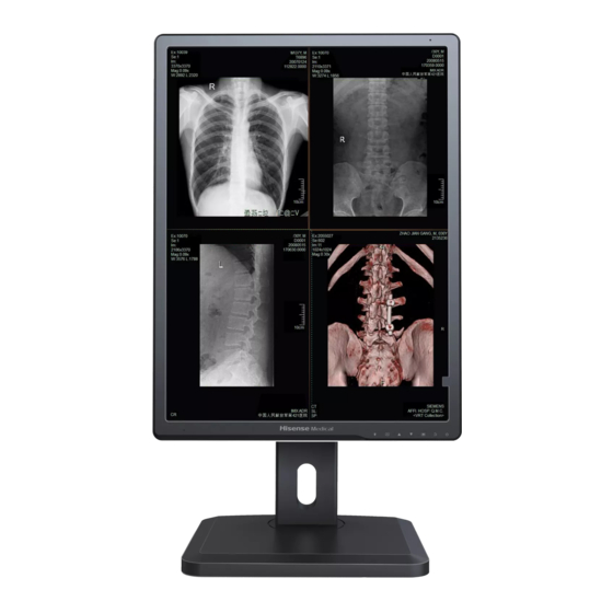
Overview Thank you for purchasing Hisense LCD monitor, which complies with the DICOM Part 14 standard and is applicable to DSA, MRI, DR, CR, CT, and PET medical imaging. It is intended for professionally trained medical staff and provides the image viewing and medical diagnostic functions. -
Page 7: Technical Specifications
Overview Technical Specifications Model HMD3C21S 1 HMD3C21E Name LCD monitor Size 21.3 inches (540 mm) Panel type Color LCD panel (IPS) Resolution 2048 (H) x 1536 (V) (mm) Display area 433.15 (H) x 324.86 (V) (mm) Pixel pitch 0.2115 (H) x 0.2115 (V) (mm) -
Page 8: Accessories
Graphics card Note The accessory list is for reference only. If any component is lost or damaged, promptly contact Hisense or the specified distributor. Keep the original package properly. If you need to return this product, be sure to use the original package. Do not place any heavy weight on top of the package during transportation. -
Page 9: Installation
Installation Front and Rear Views of the LCD Monitor Original packaging The monitor is lifted to the highest position Rotate 90° clockwise to change to vertical Rear view of the LCD monitor in vertical orientation orientation CAUTION When adjusting the height of the monitor, hold the left and right sides of the monitor with both hands. Do not put your hands directly under the monitor to avoid pinching your hands when the monitor reaches the lowest level. -
Page 10: Front View Of The Lcd Monitor And Buttons
Installation Front View of the LCD Monitor and Buttons Note For instructions on using the buttons, see the "Operational Instructions and Function Adjustment" section. -
Page 11: Rear View Of The Lcd Monitor And Input Ports
Installation Rear View of the LCD Monitor and Input Ports Port Function Power port Connected to the power adapter. Connected to a PC for LCD monitor debugging or parameter setting. Input: 5 USB1 (uplink port) V, 1 A. DP IN/DVI Connected to the digital output port on the graphics card of the PC. -
Page 12: Hanging Arm Installation
Installation Hanging Arm Installation Remove the base assembly to install the required hanging arm or base. Follow the instructions in the User Guide when installing the hanging arm or base. Before using the hanging bracket or base provided by another manufacturer, ensure that it meets the following requirements and complies with the VESA standard: –... -
Page 13: Cable Connection
Installation Cable Connection The LCD monitor provides multiple connections to a PC and allows you to switch to any of the channels for display. The following figure shows the PC connection diagram. DVI port DP OUT port DP IN port Digital Digital Digital... -
Page 14: Usb Connection
Installation Use the DP OUT terminal to connect to another monitor as follows: Output the input signals of the DP IN channel to another monitor through the DP OUT channel to implement dual-screen independent display. The daisy chain must be supported by the graphics card. DP IN port DP OUT port DP IN port... -
Page 15: Operational Instructions And Function Adjustment
Operational Instructions and Function Adjustment Operational Instructions Operational Instructions Buttons of the LCD monitor When the LCD monitor is in vertical orientation, seven adjustment buttons and a power indicator exist in the lower right corner of the monitor frame. The following table lists the functions of them. Button Function Light box button. -
Page 16: Light Box
Operational Instructions and Function Adjustment Procedure: Mode 1) Press the button on the LCD monitor to go to the Custom Mode screen. 2) Press to select a proper display mode. In Custom mode, press ▲/▼ to adjust backlight brightness. In DICOM200, DICOM250, DICOM300, DICOM350, DICOM400, DICOM450, DICOM500, DICOM600, or DICOM700 mode, press this button to switch to... -
Page 17: Menu Adjustment
Operational Instructions and Function Adjustment Menu Adjustment Main Menu Display After power-on, press to go to the User menu, and press to close the menu. The following table lists the configurable items of the menu. Main First-level Second-level Remarks Menu Menu Menu Mode... -
Page 18: Setting And Adjustment
Operational Instructions and Function Adjustment Setting and Adjustment Display Settings User menu Mode Press the button on the LCD monitor to go to Brightness the User menu. Contrast Press ▲/▼ to select the main menu item you want Saturation Gamma to adjust or set, and press... - Page 19 Operational Instructions and Function Adjustment Mode Select the display mode to be adjusted. The following table lists the initial values of all modes. Mode Brightness (cd/m Gamma Value Custom Gamma 2.2 DICOM200 DICOM DICOM250 DICOM DICOM300 DICOM DICOM350 DICOM DICOM400 DICOM DICOM450...
- Page 20 Operational Instructions and Function Adjustment Saturation Set Saturation to adjust the saturation in the current display mode. The value range is 0 to 100. The default value is 50. Gamma Set Gamma to adjust the Gamma curve displayed by an image. The options include DICOM, CT, MRI, DSA, DR, CR, 1.8, 2.0, 2.2, 2.4, and 2.6.
-
Page 21: User Menu - Power Saving Manager
Operational Instructions and Function Adjustment Other display parameters than Display Settings Lock are grayed out and cannot be Lock set. Unlock Display parameters are unlocked and can be set. Display Settings Lock Eye care: The options include Off and On. Note ... -
Page 22: User Menu - Auto Calibration Settings
Operational Instructions and Function Adjustment Body Sensor Set Body Sensor to enable or disable the body-inductive sensor. The body-inductive sensor detects actions to determine whether a user is operating the LCD monitor. If no action is detected within 10 minutes, the system automatically enters energy-saving mode, before which a 15-second countdown is started. -
Page 23: User Menu - Monitor Settings
Operational Instructions and Function Adjustment Result Select this option to view the results of the last five calibrations or validations. The results include Pass, Fail, Canceled, and Error. The system use duration at the time of calibration or validation is recorded. Note ... - Page 24 Operational Instructions and Function Adjustment LOGO Set LOGO to enable or disable the startup logo. When you select Off, the startup logo is not displayed upon power-on. When you select On, the startup logo is displayed upon power-on. The default value is On. Note ...
-
Page 25: Troubleshooting
Troubleshooting Troubleshooting Before repair, check the following table to see if you can identify the cause of the fault. If the fault persists after you follow the instructions in the User Guide, you can consider repair. Fault Symptom Solution Check whether the power plug is securely connected to the socket. -
Page 26: Safety Statement
Consult Hisense. Use the power adapter and power cable provided by Hisense, and ensure that the LCD monitor is properly connected to ground. Do not modify or retrofit the LCD monitor by yourself. Failure to comply with cause interference and damage to the LCD monitor. -
Page 27: Environmental Protection Information
Environmental Protection Information Environmental Protection Information The LCD monitor meets the environmental protection requirements of the Administrative Measures for Limiting the Use of Hazardous Substances in Electrical and Electronic Products. During its environmental-friendly service life, the LCD monitor does not cause leakage and precipitation of harmful substances and other problems affecting the health of users in the process of use, so it can be used safely. -
Page 28: Maintenance Disclaimer
User Guide but encounters equipment failure, parts damage, or monitor brightness not reaching the brightness value recommended in the User Guide, Hisense will repair or replace the product according to its own judgment. -
Page 29: Appendix: List Of Terms
Appendix: List of Terms Digital Imaging and Communications in Medicine (DICOM) DICOM was jointly developed by American College of Radiology (ACR) and National Electrical Manufacturers Association (NEMA). DICOM-compatible device connections can transmit medical images and data. DICOM Part 14 specifies the standard display functions of medical gray scale images. - Page 30 Qingdao Hisense Medical Equipment Co., Ltd. Address: North, 3F, Outsourcing Center of Software Park, No. 169, Songling Road, Laoshan District, Qingdao, P.R.China Hisense national customer service hotline: 4009940707 Hisense service supervision email: haixinfuwu@hisense.com...
Need help?
Do you have a question about the HMD3C21S and is the answer not in the manual?
Questions and answers