Holtek HT32 Series Quick Start Manual
Hide thumbs
Also See for HT32 Series:
- Manualline (12 pages) ,
- User manual (12 pages) ,
- Troubleshooting manual (18 pages)

Related Manuals for Holtek HT32 Series


Summary of Contents for Holtek HT32 Series
- Page 1 HT32 Series Microcontroller CooCox CoIDE Quick Start Revision: V1.00 Date: �01��0���� �01��0����...
-
Page 2: Table Of Contents
32-bit ARM ® Cortex -M3 MCU HT32 Series Table of Contents 1 Introduction ......................5 About the Quick Start Guide ....................5 About the CooCox CoIDE ...................... 5 2 Requirements ......................6 3 Installing the CooCox CoIDE ................. 7 4 Setting up the GCC Compiler ................10 5 Installing the USB Debug Adapter .............. - Page 3 32-bit ARM ® Cortex -M3 MCU HT32 Series List of Figures Figure 1. Step-by-step CooCox CoIDE quick start ................... 5 Figure 2. System architecture and requirements ..................6 Figure 3. Install CoIDE – Welcome ......................7 Figure 4. Install CoIDE – Select Destination Location ................7 Figure 5.
- Page 4 32-bit ARM ® Cortex -M3 MCU HT32 Series Figure 41. Open Memory View ....................... 31 Figure 42. Memory view showing address of 0x20001000 ..............31 Figure 43. Examination of memory changes ..................3� Figure 44. Mass erase function ......................33 Figure 45.
-
Page 5: Introduction
Introduction About the Quick Start Guide This objective of this quick start guide is to increase familiarity of the Holtek's HT32 series microcontrollers. The content includes information regarding the installation and configuration of the CooCox Integrated Development Environment, hereafter known as the CoIDE, for Holtek's HT32 series microcontroller. -
Page 6: Requirements
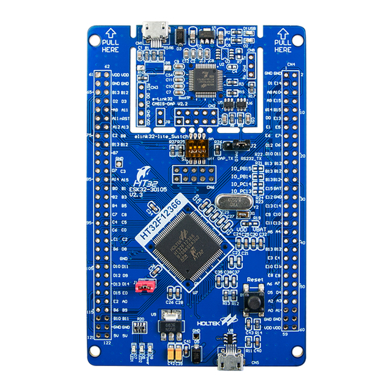
HT32 Series Requirements The following components as listed below are required: A target board with a HT32 series MCU ▆ A hardware debug adapter such as the Holtek’s e-Link32 or CoLinkEx ▆ A host computer running Microsoft ® Windows ®... -
Page 7: Installing The Coocox Coide
The evaluation software of CooCox CoIDE can be downloaded from http://www.coocox.org or a preloaded CD-ROM provided by Holtek. Step 1. Execute the installation program of the CoIDE by double-clicking on “CoIDE-x.x.x.exe” where “x.x.x” represents the version number. Press the “Next” button to continue when the screen below appears. -
Page 8: Figure 5. Install Coide - Select Start Menu Folder
32-bit ARM ® Cortex -M3 MCU HT32 Series Step 3. Select Start Menu Folder and then click the “Next” button to continue. Figure 5. Install CoIDE – Select Start Menu Folder Step 4. Click the “Install” button to start installation. -
Page 9: Figure 7. Install Coide - Installing
32-bit ARM ® Cortex -M3 MCU HT32 Series Step 5. Wait while the Setup installs the CoIDE on your computer. Figure 7. Install CoIDE – Installing Step 6. Setup has finished installing on your computer. Figure 8. Install CoIDE – Completing Rev. -
Page 10: Setting Up The Gcc Compiler
32-bit ARM ® Cortex -M3 MCU HT32 Series Setting up the GCC Compiler Before using the CoIDE to implement a project it is necessary to first configure the GCC compiler and debugger. The following steps show how to install the compiler. -
Page 11: Installing The Usb Debug Adapter
After the CoIDE has been installed, the e-Link32 debug adapter driver must also be installed. The following steps show how to install the driver. Step 1. Get the latest version of the driver from the Holtek website or the Holtek supplied CD-ROM. The filename is similar to “e-Link32-USB_Driver_vnnn.exe” where “nnn”... -
Page 12: Figure 12. Install E-Link32 Usb Driver - Select Destination Location
32-bit ARM ® Cortex -M3 MCU HT32 Series Step 3. Select the destination location where the driver is to be installed and then click the “Next” button to continue. Figure 12. Install e-Link32 USB driver – Select Destination Location Step 4. Press the “Next” button to continue when the screen below appears. -
Page 13: Figure 14. Install E-Link32 Usb Driver - Completing
Step 2. The system will detect a USB device and starts the driver installation procedure. Step 3. Specify the driver path manually according to the USB debug adapter. “C:\Program Files\Holtek HT32 Series\e-Link32 USB Driver\” – for e-Link32 Rev. 1.00 13/35... -
Page 14: Connecting To The Target Board
® Cortex -M3 MCU HT32 Series Connecting to The Target Board The target board can be powered via the USB port or a 5V DC adaptor by changing the on-board jumpers. Refer to the corresponding target board documentation for details. -
Page 15: Coocox Coide Quick Start
32-bit ARM ® Cortex -M3 MCU HT32 Series CooCox CoIDE Quick Start CooCox provides a complete development tool, “CoIDE”, that can create a project, edit C code, setup the development tools, implement connections and perform tests. Visit the CooCox web site http://www.coocox.org... -
Page 16: Figure 17. Create New Project Dialog
3. A “New Project” dialog will pop up. Specify the name and path of the project and press the “Finish” button. The related information and files can then be found in the “Project” window. Figure 17. Create new project dialog 4. Select Holtek manufacturer for the project. Figure 18. Select manufacturer for the project Rev. 1.00 16/35 �01��0����... -
Page 17: Figure 19. Select Chip For The Project
32-bit ARM ® Cortex -M3 MCU HT32 Series 5. Select chip, for example: HT32F1755. The right side will display the corresponding chip information. Figure 19. Select Chip for the project 6. Check a component. For example, select “GPIO”. The CoIDE will automatically check the components which the checked component depend upon. -
Page 18: Figure 21. Review The Result In Component View
32-bit ARM ® Cortex -M3 MCU HT32 Series 7. Review the results in Component View. Figure 21. Review the result in Component View Rev. 1.00 1�/35 �01��0����... -
Page 19: Setting Project Options
32-bit ARM ® Cortex -M3 MCU HT32 Series Setting Project Options The following section describes how to setup the USB debug adapter and Flash Loader. Configure the USB Debug Adapter The following is the method to configure the CoIDE USB debug adapter. This example will use the e-Link32. -
Page 20: Figure 23. Debug Configurations Dialog - Open Configuration Page
32-bit ARM ® Cortex -M3 MCU HT32 Series 3. Click “{PROJECT NAME}.configuration” in the left side of the Debug Configuration dialog to open the configuration page. Figure 23. Debug Configurations Dialog – Open Configuration Page 4. Select e-Link32 as the adapter in the Debugger tab. If “Run to main()” is checked, the application will first be run to “main()”... -
Page 21: Setting Flash Loader
® Cortex -M3 MCU HT32 Series Setting Flash Loader The Flash loader is used to download the program into the on-chip Flash memory. It is an agent that acts on the SRAM to receive data from the host PC (through the USB debug adapter) and program this data into the Flash memory. - Page 22 32-bit ARM ® Cortex -M3 MCU HT32 Series 3. Click the “Add…” button and choose “HT32_xxx” from the list box as below. Where xxx means the size of target device. Figure 26. Select Flash loader dialog Rev. 1.00 ��/35 �01��0����...
-
Page 23: Adding New File To The Project
® Cortex -M3 MCU HT32 Series Adding New File to The Project Source code can be added to the project as shown below. 1. Right-click on a folder which is the location of the new file, in the “Project” view to display the Context Menu and choose “New File”... -
Page 24: Figure 28. Type New File Name
32-bit ARM ® Cortex -M3 MCU HT32 Series 2. Type “AddFile.c” into the “File name” input box. Click “Finish” button. Figure 28. Type New File Name 3. Edit the code as shown below in the editor window. Click “File → Save”... -
Page 25: Adding A Linked File To The Project
® Cortex -M3 MCU HT32 Series Adding a Linked File to the Project A pre-existing file can be can be added into the project as shown below. 1. Right-Click on a folder, which is the virtual location of the linked file, in the “Project” view to display the Context Menu and choose “Add Linked File”... -
Page 26: Compiling The Project
32-bit ARM ® Cortex -M3 MCU HT32 Series Compiling The Project To compile the project: 1. Choose “Project → Rebuild” to recompile all the files in the project. Figure 31. Rebuild Project 2. Check the Build message in the “Console View” window to confirm if the project has been successfully built and linked. -
Page 27: Download And Debug
32-bit ARM ® Cortex -M3 MCU HT32 Series Download and Debug The following section shows how to download the application and use debug features such as free running, break, single step and breakpoint. Enter/Exit Debug Mode 1. Click “Debug → Debug (Ctrl + F5)” or “Start Debug” icon to enter the debug mode. The image will be downloaded into Flash memory automatically (when the “Auto Download Before... -
Page 28: Figure 34. Terminate Debug
32-bit ARM ® Cortex -M3 MCU HT32 Series 2. After the debugging has finished, click “Debug → Terminate (Ctrl + F5)” or “Terminate” icon to exit the debug mode. Figure 34. Terminate Debug 3. The debug window is shown below. There is information about “Registers”, “Disassembly”, “Source Code Window”, “Memory”, “Variables”... -
Page 29: Free Running, Break, And Single Step
32-bit ARM ® Cortex -M3 MCU HT32 Series Free Running, Break, and Single Step The debugger provides Free Running, Break and Single Step functions to assist with application debug. 1. Click the “Run” icon to start the program free running. -
Page 30: Figure 40. Stop At Breakpoint
32-bit ARM ® Cortex -M3 MCU HT32 Series Using Breakpoint 1. Double click on the line to set a breakpoint before the program starts running. A red point will then appear in front of the line. Figure 39. Add a breakpoint 2. -
Page 31: Using Memory View
32-bit ARM ® Cortex -M3 MCU HT32 Series Using Memory View 1. Click “View → Memory” to open memory view. Figure 41. Open Memory View 2. Type “0x20001000” into the “Address” input box to view the value in the memory. -
Page 32: Figure 43. Examination Of Memory Changes
32-bit ARM ® Cortex -M3 MCU HT32 Series 3. Click the “Step” icon or “F11” to single step the program. Use this feature to examine the memory changes. Figure 43. Examination of memory changes Rev. 1.00 3�/35 �01��0����... -
Page 33: Mass Erase
® Cortex -M3 MCU HT32 Series Mass Erase Mass erase is an operation that erases the complete Flash Memory including the main Flash and the Option Bytes. It can be used to clear all the data in the flash or to disable the security settings. -
Page 34: Conclusion
CooCox CoIDE for Holtek's HT32 series microcontrollers. Now, start creating your own application using the HT32 series microcontrollers. Holtek provides a related firmware library, example code, documents and services to reduce the development cycle and thus speed up the time to the market. - Page 35 Holtek's products are not authorized for use as critical components in life support devices or systems. Holtek reserves the right to alter its products without prior notification.
Need help?
Do you have a question about the HT32 Series and is the answer not in the manual?
Questions and answers