Table of Contents
Advertisement
Quick Links
Advertisement
Table of Contents

Subscribe to Our Youtube Channel
Related Manuals for Holtek HT32 MCU


Summary of Contents for Holtek HT32 MCU
- Page 1 HT32 MCU Starter Kit User Manual Revision: V1.10 Date: August 12, 2020...
-
Page 2: Table Of Contents
HT32 MCU Starter Kit User Manual Table of Contents 1 Introduction ......................5 Features ..........................5 2 Hardware Layout ..................... 6 Separating the e-Link32 Lite ......................7 Serial Wire Debug Interface Switch – S1 ..................8 SWD-10P Connector – CN2, CN6 ....................8 e-Link32 Lite Power Option –... - Page 3 HT32 MCU Starter Kit User Manual List of Tables Table 1. SWD-10P Connector ........................8 Table 2. Extension Connector 1 .......................11 Table 3. Extension Connector 2 ......................12 Table 4. Micro USB Type B Connector ....................13 Rev. 1.10 3 of 20...
- Page 4 HT32 MCU Starter Kit User Manual List of Figures Figure 1. HT32 Starter Kit ......................... 5 Figure 2. HT32 Starter Kit Block Diagram ....................6 Figure 3. HT32 Starter Kit Layout – using the ESK32-30501 V2.0 as an example ........7 Figure 4.
-
Page 5: Introduction
Cortex ® -M0+/M3 high performance microcontroller and is designed to assist users to get up and running with the Holtek 32-bit device range as quickly as possible. Standard C language programs can be developed using the integrated development environment from Keil μVision and IAR EWARM. Using this foundation, Holtek also provides a comprehensive function library to avoid complicated lower level function development in order to allow designers to focus their time on their specific application development. -
Page 6: Hardware Layout
HT32 MCU Starter Kit User Manual Hardware Layout Micro 3.3V USB LED State LED e-Link32 Adjustment Voltage e-Link32 Lite SWD-10P translation CMSIS-DAP UART Jumper switch SWD-10P 8 MHz 32.768 kHz HT32 MCU ARM Cortex- M0+/M3 Microcontroller Target Board reset 5V-to-3.3V... -
Page 7: Separating The E-Link32 Lite
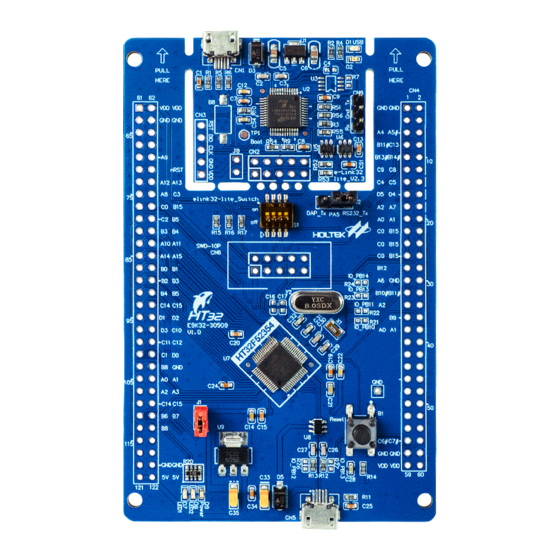
HT32 MCU Starter Kit User Manual Figure 3. HT32 Starter Kit Layout – using the ESK32-30501 V2.0 as an example Separating the e-Link32 Lite Not Separated (Default) Separated Rev. 1.10 7 of 20 August 12, 2020... -
Page 8: Serial Wire Debug Interface Switch - S1
HT32 MCU Starter Kit User Manual Serial Wire Debug Interface Switch – S1 Description Connect the SWD interface between the e-Link32 Lite and the Target MCU – default setting Disconnect the SWD interface between the e-Link32 Lite and the Target MCU SWD-10P Connector –... -
Page 9: E-Link32 Lite Power Option - R8
HT32 MCU Starter Kit User Manual e-Link32 Lite Power Option – R8 Description Pin 1 on the CN2 connector on the e-Link32 Lite side is used as the input. The reference voltage is supplied through this pin to the voltage conversion chip – default setting Note that if the e-Link32 Lite has not been separated, the 3.3V on the Target Board... -
Page 10: Low Speed External Crystal Oscillator (Lse) Option
HT32 MCU Starter Kit User Manual Low Speed External Crystal Oscillator (LSE) Option R21 & R22 Description Open, LSE I/O pins disconnected from CN4 – default setting Short, LSE I/O pins connected to CN4 pins 31 and 32. X1 must be removed. -
Page 11: E-Link32 Uart Connector - Cn8
HT32 MCU Starter Kit User Manual e-Link32 UART Connector – CN8 This is the e-Link32 integrated USB to UART function, which is called the “Virtual COM port”, CN8 is the UART side connector. Description Three UART connector pins: Txd, GND and Rxd... -
Page 12: Extension Connector Cn4-2
HT32 MCU Starter Kit User Manual Pin No. Description Pin No. Description CSIF_D6 CSIF_D7 CSIF_D4 CSIF_D5 CSIF_D2 CSIF_D3 CSIF_D0/USB D- CSIF_D1/USB D+ 3.3V 3.3V Extension connector CN4-2 Figure 6. Extension Connector 2 Table 3. Extension Connector 2 Pin No. -
Page 13: Micro Usb Type B Connector - Cn5
HT32 MCU Starter Kit User Manual Pin No. Description Pin No. Description Button1 Button2 LED0 LED1 LED2 SCI_CMD SCI_RST SCI_CLK SCI_DET SCI_DIO Micro USB Type B Connector – CN5 Figure 7. Micro USB Type B Connector Table 4. Micro USB Type B Connector Pin No. -
Page 14: Connection Between The E-Link32 Lite And The Target Board
HT32 MCU Starter Kit User Manual Connection between the e-Link32 Lite and the Target Board e‐Link32 Lite v2.0 Target Board Figure 8. Connection between the e-Link32 Lite V2.0 and the Target Board e‐Link32 Lite v2.3 Target Board Figure 9. Connection between e-Link32 Lite V2.3 and Target Board Rev. -
Page 15: Schematics
Lite V2.0 ▆ e-Link32 Lite V2.2 ▆ e-Link32 Lite V2.3 ▆ HT32F52352 Target Board – ESK32-30501 ▆ Other Starter Kit target board circuit diagrams can be downloaded on Holtek official website. Rev. 1.10 15 of 20 August 12, 2020... -
Page 16: Figure 10. E-Link32 Lite V2.0
R1 1M D+ ID D1 USB R2 330 LED1 0.1uF Earth_2 Earth_2 VDD_elink32 Green VDD_elink32 D2 Err USB-Micro VDD_elink32 R4 330 LED2 HT7833 47pF 47pF USBDP_elink USBDM_elink HT32F165x_LQFP48 DC5V VDD_elink32 FLASH VDD_elink32 SS-12W,SS-13W,SS-14W Flash_CS 10UF VSS33_3 10k (NC) VDD33_3 VDD_elink32 MISO VDD_elink32 10UF... -
Page 17: Figure 11. E-Link32 Lite V2.2
R1 1M D+ ID D1 USB R2 330 LED1 0.1uF Earth_2 Earth_2 VDD_elink32 Green VDD_elink32 D2 Err USB-Micro VDD_elink32 R4 330 LED2 HT7833 47pF 47pF USBDP_elink USBDM_elink HT32F165x_LQFP48 DC5V VDD_elink32 FLASH VDD_elink32 SS-12W,SS-13W,SS-14W Flash_CS 10UF VSS33_3 10k (NC) VDD33_3 VDD_elink32 MISO 10UF VDD_elink32... -
Page 18: Figure 12. E-Link32 Lite V2.3
VDD_elink32 UART Interface LED1 USB Port Green LEDs LED_0603 0603-R Virtual COM Port HDR1X3 LED2 R1 1M 0603-R D+ ID LED_0603 0603-R Earth_2 Earth_2 0.1uF R56 100 0603-R 0603-C DAP_RX DAP_RX USB-Micro DAP_TX DAP_TX USB-Micro VDD_elink32 R51 100 0603-R 47pF 47pF VDD_elink32 0603-C... -
Page 19: Figure 13. Ht32F52352 Target Board - Esk32-30501
MVDD VDD33 3.3V 3.3V VDD33 PC11 PC10 I2S_BCLK I2S_WS 2.2uF 0.1uF PA1_CTS/I2C PA0_RTS/I2C RS232_TX I2S_SDA I2S_SCL RS232_RX RS232_TX PC12 PC13 PA9_BOOT1/M PA10 I2S_SDO I2S_SDI M_IO4 BUZZER PA9_BOOT1/M PB13 PB14 BOOT1 I2S_MCLK M_IO2 M_IO3 F_NRST PB15 PC0_LCD/M nRST M_IO0 M_IO1 HT32F52352_LQFP64 PA12 PA13 SWCLK... - Page 20 Holtek's products are not authorized for use as critical components in life support devices or systems. Holtek reserves the right to alter its products without prior notification. For the most up-to-date information, please visit our web site at http://www.
Need help?
Do you have a question about the HT32 MCU and is the answer not in the manual?
Questions and answers