
Related Manuals for Mitsubishi Electric TM-RFM


Summary of Contents for Mitsubishi Electric TM-RFM
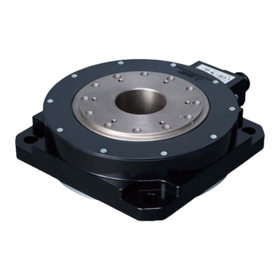
- Page 1 General-Purpose AC Servo MODEL TM-RFM TM-RG2M TM-RU2M DIRECT DRIVE MOTOR INSTRUCTION MANUAL...
- Page 2 Safety Instructions Please read the instructions carefully before using the equipment. To use the equipment correctly, do not attempt to install, operate, maintain or inspect the equipment until you have read through this Instruction Manual and appended documents carefully. Do not use the equipment until you have a full knowledge of the equipment, safety information and instructions.
- Page 3 1. To prevent electric shock, note the following WARNING Before wiring and inspections, turn off the power and wait for 15 minutes or more until the charge lamp turns off. Otherwise, an electric shock may occur. In addition, when confirming whether the charge lamp is off or not, always confirm it from the front of the servo amplifier.
- Page 4 4. Additional instructions The following instructions should also be fully noted. Incorrect handling may cause a malfunction, injury, electric shock, fire, etc. (1) Transportation and installation CAUTION Transport the products correctly according to their mass. Stacking in excess of the specified number of product packages is not allowed. Do not hold the cables, rotor, encoder, or connector when carrying the direct drive motor.
- Page 5 CAUTION Do not apply shocks, e.g. hit with a hammer, when coupling the rotor of the direct drive motor. Otherwise, the encoder may malfunction. Do not subject the rotor of the direct drive motor to more than the permissible load. Otherwise, the rotor may break.
- Page 6 (3) Test run and adjustment CAUTION Before operation, check the parameter settings. Improper settings may cause some machines to operate unexpectedly. Never make a drastic change to the parameter values as doing so will make the operation unstable. (4) Usage CAUTION Provide an external emergency stop circuit to ensure that operation can be stopped and power switched off immediately.
- Page 7 (6) Storage CAUTION Note the followings when storing the direct drive motor for an extended period of time (guideline: three months or more). Always store the direct drive motor indoors in a clean and dry place. If it is stored in a dusty or damp place, make adequate provision, e.g. cover the whole product. If the insulation resistance of the winding decreases, check how to store the equipment.
-
Page 8: Table Of Contents
CONTENTS 1. INTRODUCTION 1 - 1 to 1 - 2 1.1 Rating plate ............................1 - 1 1.2 Parts identification ..........................1 - 1 2. INSTALLATION 2 - 1 to 2 - 8 2.1 Equipment configuration ........................2 - 2 2.2 Mounting direction.......................... - Page 9 7. TM-RFM SERIES 7 - 1 to 7 -12 7.1 Model code definition ........................7 - 1 7.2 Combinations of servo amplifier and direct drive motor ..............7 - 2 7.3 Specification list ..........................7 - 3 7.4 Torque characteristics ........................7 - 6 7.5 Dimensions ............................
-
Page 10: Introduction
1. INTRODUCTION 1. INTRODUCTION 1.1 Rating plate The following shows an example of rating plate for explanation of each item. Model Input power, rated torque, and mass Insulation class, rated speed, and maximum ambient temperature Induced voltage constant, IP rating, and serial number (Note 1) Conforming standards, and Country of origin... - Page 11 1. INTRODUCTION MEMO 1 - 2...
-
Page 12: Installation
2. INSTALLATION 2. INSTALLATION WARNING To prevent electric shock, ground each equipment securely. Stacking in excess of the specified number of product packages is not allowed. Install the direct drive motor on incombustible material. Installing them directly or close to combustibles will lead to smoke or a fire. Install the servo amplifier and the direct drive motor in a load-bearing place in accordance with the Instruction Manual. -
Page 13: Equipment Configuration
2. INSTALLATION 2.1 Equipment configuration The following shows the configuration of a direct drive motor. When using the direct drive motor, note the following. (1) Minimum oscillation angle If the direct drive motor rotates repeatedly by a small angle (by 70 or less), make the direct drive motor rotate by 90 ... -
Page 14: Mounting Direction
2. INSTALLATION 2.2 Mounting direction The following table indicates the mounting direction of the direct drive motor. Direct drive motor series Mounting direction TM-RFM TM-RG2M All directions TM-RU2M 2.3 Load mounting/dismounting precautions POINT During assembling, the rotor must not be hammered. Otherwise, the encoder may malfunction. -
Page 15: Protection From Oil And Water
2. INSTALLATION 2.5 Protection from oil and water Provide adequate protection to prevent foreign matter, such as oil and water, from entering the rotor of the direct drive motor. When mounting the direct drive motor, consider the items in this section. (1) Do not use the direct drive motor with its cable soaked in oil or water. -
Page 16: Inspection Items
2. INSTALLATION 2.6 Inspection items Before starting maintenance and/or inspection, turn off the power and wait for 15 minutes or more until the charge lamp turns off. Then, confirm that the voltage between P+ and N- is safe with a voltage tester and others. Otherwise, an electric WARNING shock may occur. -
Page 17: Machine Accuracies
2. INSTALLATION 2.8 Machine accuracies The following table indicates the machine accuracies of the rotor (output shaft) and the mounting area of the direct drive motor (except special products). Measuring Item Accuracy [mm] position Runout of mounting surface to rotor 0.05 (output shaft) Runout of fitting outer diameter of... -
Page 18: Restrictions When Using This Product At Altitudes Exceeding 1000 M And Up To 2000 M Above Sea Level
2. INSTALLATION 2.10 Restrictions when using this product at altitudes exceeding 1000 m and up to 2000 m above sea level As heat dissipation effects decrease in proportion to the decrease in air density, use the product within the effective load ratio and regenerative load ratio shown in the following figure. 1000 2000 Altitude... - Page 19 2. INSTALLATION MEMO 2 - 8...
-
Page 20: Connectors Used For Direct Drive Motor Wiring
3. CONNECTORS USED FOR DIRECT DRIVE MOTOR WIRING 3. CONNECTORS USED FOR DIRECT DRIVE MOTOR WIRING POINT The IP rating indicated is the connector's protection against ingress of dust and water when the connector is connected to a servo amplifier, direct drive motor, or absolute position storage unit. -
Page 21: Wiring Connectors (Connector Configurations A/B/C/D/E/F)
3. CONNECTORS USED FOR DIRECT DRIVE MOTOR WIRING 3.2 Wiring connectors (connector configurations A/B/C/D/E/F) Cord clamp Plug Recommended cable Direct drive motor encoder Plug (Hirose Electric) connector (Bando Densen) Connector Feature Absolute position storage Cable OD configuration unit connector Type Plug Cord clamp Model... - Page 22 3. CONNECTORS USED FOR DIRECT DRIVE MOTOR WIRING Plug Cable clamp Plug (DDK) Cable clamp (DDK) Connector Direct drive motor power Cable OD Feature configuration connector (Note 2) Type Model Model [mm] (reference) 8.5 to 11 CE3057-10A-2-D IP67 CE05-6A18-10SD-D-BSS EN compliant Applicable wire size: AWG 14 to 12 10.5 to 14.1 CE3057-10A-1-D...
- Page 23 3. CONNECTORS USED FOR DIRECT DRIVE MOTOR WIRING Cord Plug clamp Plug (Hirose Electric) Recommended cable (Bando Densen) Absolute position storage Connector Cable OD unit connector Feature configuration Type Plug Cord clamp Model [mm] (encoder side) (Note 1) (reference) 20276 VSVPAWG#23×6P IP67 Straight...
-
Page 24: Connector Dimensions
4. CONNECTOR DIMENSIONS 4. CONNECTOR DIMENSIONS The following shows the dimensions of the connectors used for wiring the direct drive motor. (1) Hirose Electric (a) RM15WTPZK-12S/RM15WTPZ-12P(72) Connector Model configuration (Note) RM15WTPZK-12S RM15WTPZ-12P(72) Note. Refer to section 3.2 for the connector configuration. [Unit: mm] Spanner hook gap dimension: 18 M16 ×... - Page 25 4. CONNECTOR DIMENSIONS (b) CE05-6A18-10SD-D-BSS CE05-6A22-22SD-D-BSS CE05-6A32-17SD-D-BSS [Unit: mm] Positioning key Connector configuration Model C ± 0.8 D or less -0.38 (Note) CE05-6A18-10SD-D-BSS 1 1/8-18UNEF-2B 34.13 32.1 1-20UNEF-2A CE05-6A22-22SD-D-BSS 1 3/8-18UNEF-2B 40.48 38.3 1 3/16-18UNEF-2A CE05-6A32-17SD-D-BSS 2-18UNS-2B 56.33 54.2 1 3/4-18UNS-2A Note.
- Page 26 4. CONNECTOR DIMENSIONS (d) D/MS3106B14S-2S D/MS3106B18-10S D/MS3106B22-22S D/MS3106B32-17S [Unit: mm] L or less W or more J ± 0.12 Connector Model configuration (Note) D/MS3106B14S-2S 7/8-20UNEF 13.49 42.88 28.57 3/4-20UNEF 8.00 D/MS3106B18-10S 1 1/8-18UNEF 18.26 52.37 34.13 1-20UNEF 9.53 D/MS3106B22-22S 1 3/8-18UNEF 18.26 56.57 40.48 1 3/16-18UNEF 9.53...
- Page 27 4. CONNECTOR DIMENSIONS (3) Daiwa Dengyo [Unit: mm] Hexagonal width Hexagonal width across flats φD2 across flats D O-ring Width Width Width Width Length before Connector across across across across Applicable tightening Model configuration flats corners flats corners cable OD (Note) YSO14-5 to 8 4 to 8.3...
-
Page 28: Connection Of Servo Amplifier And Direct Drive Motor
5. CONNECTION OF SERVO AMPLIFIER AND DIRECT DRIVE MOTOR 5. CONNECTION OF SERVO AMPLIFIER AND DIRECT DRIVE MOTOR Any person who is involved in wiring should be fully competent to do the work. Ground the direct drive motor securely. Do not attempt to wire the direct drive motor until it has been installed. Otherwise, it may cause an electric shock. -
Page 29: Connection Instructions
5. CONNECTION OF SERVO AMPLIFIER AND DIRECT DRIVE MOTOR 5.1 Connection instructions To avoid a malfunction, connect the power supply phases (U/V/W) of the servo amplifier and the direct drive motor correctly. CAUTION Do not connect AC power supply directly to the direct drive motor. Otherwise, it may cause a malfunction. -
Page 30: Selection Example Of Wires
Construction condition: Single wire set in midair. Wire length: 30 m or less The following shows examples for using the 600 V Grade heat-resistant polyvinyl chloride insulated wire (HIV wire). (1) TM-RFM series Wire [mm Direct drive motor U/V/W/ TM-RFM002C20... -
Page 31: Servo Amplifier Terminal Section
5. CONNECTION OF SERVO AMPLIFIER AND DIRECT DRIVE MOTOR 5.4 Servo amplifier terminal section POINT For the sizes of wires used for wiring, refer to section 5.3. When wiring, remove the power connectors from the servo amplifier. Insert only one wire or ferrule to each wire insertion hole. To wire to the servo amplifier, use connectors packed with the servo amplifier or optional connectors. - Page 32 5. CONNECTION OF SERVO AMPLIFIER AND DIRECT DRIVE MOTOR (1) Connector details (a) Connector A Servo amplifier CNP3 Table 5.1 Connector and applicable wire Applicable wire Stripped Manufac- Connector Receptacle assembly Open tool length [mm] turer Wire size Insulator OD J-FAT-OT (N) CNP3 03JFAT-SAXGDK-H7.5...
- Page 33 5. CONNECTION OF SERVO AMPLIFIER AND DIRECT DRIVE MOTOR (c) MR-J4W_ - _B Servo amplifier CNP3A CNP3B CNP3C (Note) Note. For the 3-axis servo amplifier. Table 5.3 Connector and applicable wire Applicable wire Stripped length Connector Receptacle assembly Open tool Manufacturer size [mm]...
- Page 34 5. CONNECTION OF SERVO AMPLIFIER AND DIRECT DRIVE MOTOR (b) Inserting wire Insert the open tool as follows and push down it to open the spring. While the open tool is pushed down, insert the stripped wire into the wire insertion hole. Check the wire insertion depth, and make sure that the cable insulator will not be caught by the spring and that the conductive part of the stripped wire will not be exposed.
- Page 35 5. CONNECTION OF SERVO AMPLIFIER AND DIRECT DRIVE MOTOR MEMO 5 - 8...
-
Page 36: Wiring Option
6. WIRING OPTION 6. WIRING OPTION Before connecting any option or peripheral equipment, turn off the power and wait for 15 minutes or more until the charge lamp turns off. Then, confirm that the WARNING voltage between P+ and N- is safe with a voltage tester and others. Otherwise, an electric shock may occur. -
Page 37: Combinations Of Connector Set
(Note 3) CN2C (Note 3) Direct drive motor TM-RFM TM-RG2M TM-RU2M Note 1. Connectors for 3.5 kW or less. For 5 kW or more, it is a terminal block. 2. Always make connection for use in an absolute position detection system. (Refer to section 6.3.) 3. -
Page 38: Connector List
6. WIRING OPTION 6.1.2 Connector list Product Model Description Remark Power connector MR-PWCNF Plug: CE05-6A14S-2SD-D (DDK) IP67 Cable clamp: YSO14-9 to 11 (Daiwa Dengyo) For TM-RFM_C20 compliant Applicable cable For TM-RFM_E20 Applicable wire size: 0.3 mm (AWG 22) to 1.25 (AWG 16) For TM-RG2M_C30 Cable outer diameter: 8.3 mm to 11.3 mm... -
Page 39: Encoder Connector Set
6. WIRING OPTION 6.2 Encoder connector set POINT The encoder cable should be fabricated by the customer. Fabricate the encoder cable according to section 6.2.1 to section 6.2.3 and the wiring diagram in section 6.2.4. Fabricate the encoder cable to be 50 m or shorter between the servo amplifier and the direct drive motor. -
Page 40: Mr-J3Ddsps
(AWG 20) 6.2.3 Combinations for the encoder cable (1) For incremental system MR-J4 1-axis servo amplifier 50 m or shorter (Note 1) Encoder cable A Direct drive motor TM-RFM TM-RG2M TM-RU2M MR-J4 multi-axis servo amplifier CN2A CN2B (Note 2) CN2C Note 1. - Page 41 6. WIRING OPTION 6.2.4 Fabrication of the encoder cable (1) Encoder cable A (a) Connector details 1) CN2, CN2A, CN2B, and CN2C side connector 2) Encoder-side connector Receptacle: 36210-0100PL Connector set: 54599-1019 Straight plug: RM15WTPZK-12S Shell kit: 36310-3200-008 (Molex) Cord clamp: JR13WCCA-8(72) (3M) (Hirose Electric) Recommended cable:...
- Page 42 6. WIRING OPTION (2) Encoder cable B (a) Connector details 4) Absolute position storage unit-side 3) CN2, CN2A, CN2B, and CN2C side connector connector Receptacle: 36210-0100PL Connector set: 54599-1019 Straight plug: RM15WTPZK-12S Shell kit: 36310-3200-008 (Molex) Cord clamp: JR13WCCA-8(72) (3M) (Hirose Electric) Recommended cable: 20276 VSVPAWG#23×6P KB-0492...
- Page 43 6. WIRING OPTION (3) Encoder cable C (a) Connector details 5) Absolute position storage unit-side 6) Encoder-side connector connector Straight plug: RM15WTPZ-12P(72) Straight plug: RM15WTPZK-12S Cord clamp: JR13WCCA-8(72) Cord clamp: JR13WCCA-8(72) (Hirose Electric) (Hirose Electric) Recommended cable: Recommended cable: 20276 VSVPAWG#23×6P KB-0492 (Note 2) 20276 VSVPAWG#23×6P KB-0492 (Note 2) (Bando Densen) (Bando Densen)
- Page 44 6. WIRING OPTION 6.3 Absolute position storage unit MR-BTAS01 POINT Replacing the MR-BTAS01 absolute position storage unit will erase the absolute position. Start up the direct drive motor again and perform home positioning according to each servo amplifier instruction manual. For absolute position detection system, refer to each servo amplifier instruction manual.
- Page 45 6. WIRING OPTION MEMO 6 - 10...
-
Page 46: Tm-Rfm Series
7. TM-RFM SERIES This chapter provides information on the direct drive motor specifications and characteristics. When using the TM-RFM series direct drive motor, always read the Safety Instructions in the beginning of this manual in addition to this chapter. 7.1 Model code definition The following describes what each block of a model name indicates. -
Page 47: Combinations Of Servo Amplifier And Direct Drive Motor
7. TM-RFM SERIES 7.2 Combinations of servo amplifier and direct drive motor Servo amplifier Direct drive motor 1-axis 2-axis 3-axis 200 V class 100 V class MR-J4-20A MR-J4-20A1 MR-J4-20A-RJ MR-J4-20B MR-J4-20A1-RJ MR-J4W2-22B MR-J4W3-222B TM-RFM002C20 MR-J4-20B-RJ MR-J4-20B1 MR-J4W2-44B MR-J4W3-444B MR-J4-20GF MR-J4-20B1-RJ... -
Page 48: Specification List
7. TM-RFM SERIES 7.3 Specification list Direct drive motor TM-RFM series Item 002C20 004C20 006C20 006E20 012E20 018E20 Motor OD (frame OD) [mm] φ130 φ180 Refer to "USING A DIRECT DRIVE MOTOR" of each servo amplifier instruction Power supply capacity manual. - Page 49 7. TM-RFM SERIES TM-RFM series Direct drive motor Item 012G20 048G20 072G20 040J10 120J10 240J10 Motor OD (frame OD) [mm] φ230 φ330 Refer to "USING A DIRECT DRIVE MOTOR" of each servo amplifier instruction Power supply capacity manual. Rated output...
- Page 50 7. TM-RFM SERIES Note 1. When the power supply voltage drops, the output and the rated speed cannot be guaranteed. 2. If the load inertia moment ratio exceeds the indicated value, contact your local sales office. 3. To configure the absolute position detection system, always connect the battery and absolute position storage unit to the servo amplifier.
-
Page 51: Torque Characteristics
7. TM-RFM SERIES 7.4 Torque characteristics POINT For the machine where the unbalanced torque occurs, such as a vertical axis system (lift), use the absolute position detection system. (Refer to section 2.1 (4).) The unbalanced torque of the machine should be kept at 70% or lower of the motor's rated torque. -
Page 52: Dimensions
7. TM-RFM SERIES 7.5 Dimensions The actual dimensions may be 1 mm to 3 mm larger. Design the machine side with some allowances. Apply general tolerances for the dimensions without tolerances. Moment of inertia J Output Mass Model [kg] [× 10 kg•m... - Page 53 7. TM-RFM SERIES Output Moment of inertia J Mass Model [kg] [× 10 kg•m TM-RFM006C20 22.4 [Unit: mm] 6-M5 screw 92.5 4-φ9 mounting hole hole depth 8 45° Use hexagon socket 60° head cap screw Z-phase mark Bottom Caution plate...
- Page 54 7. TM-RFM SERIES Output Moment of inertia J Mass Model [kg] [× 10 kg•m TM-RFM012E20 [Unit: mm] 4-φ14 mounting hole 6-M5 screw Use hexagon socket 60° 45° hole depth 8 head cap screw Z-phase mark Bottom Caution plate Motor plate...
- Page 55 7. TM-RFM SERIES Output Moment of inertia J Mass Model [kg] [× 10 kg•m TM-RFM012G20 [Unit: mm] 6-M6 screw hole depth 10 4-φ14 mounting hole 60° 45° 2 × 2-M10 screw hole depth 19.5 Use hexagon socket head cap screw 14.5...
- Page 56 7. TM-RFM SERIES Output Moment of inertia J Mass Model [kg] [× 10 kg•m TM-RFM072G20 1508 [Unit: mm] 4-φ14 mounting hole Use hexagon socket 6-M6 screw head cap screw hole depth 10 45° 60° 2 × 2-M10 screw hole depth 19.5 14.5...
- Page 57 7. TM-RFM SERIES Output Moment of inertia J Mass Model [kg] [× 10 kg•m TM-RFM120J10 2513 3519 [Unit: mm] 162.5 2 × 2-M12 screw hole depth 25.5 6-M8 screw 4-φ18 mounting hole hole depth 13 Use hexagon socket 45° head cap screw 60°...
-
Page 58: Tm-Rg2M Series/Tm-Ru2M Series
8. TM-RG2M SERIES/TM-RU2M SERIES 8. TM-RG2M SERIES/TM-RU2M SERIES This chapter provides information on the direct drive motor specifications and characteristics. When using the TM-RG2M series or TM-RU2M series direct drive motor, always read the Safety Instructions in the beginning of this manual in addition to this chapter. 8.1 Model designation The following describes model designation. -
Page 59: Combinations Of Servo Amplifier And Direct Drive Motor
8. TM-RG2M SERIES/TM-RU2M SERIES 8.2 Combinations of servo amplifier and direct drive motor Servo amplifier 1-axis 2-axis 3-axis For increasing For increasing For increasing Direct drive motor the rated the rated the rated Standard Standard Standard torque/maximum torque/maximum torque/maximum torque (Note) torque (Note) torque (Note) MR-J4-20A... -
Page 60: Specification List
8. TM-RG2M SERIES/TM-RU2M SERIES 8.3 Specification list Direct drive motor TM-RG2M/RU2M series Item 002C30 004E30 009G30 Motor OD (frame OD) [mm] φ130 φ180 φ230 Refer to "USING A DIRECT DRIVE MOTOR" of each servo amplifier instruction Power supply capacity manual. Rated output 141 (188) (Note 9) - Page 61 8. TM-RG2M SERIES/TM-RU2M SERIES Note 1. When the power supply voltage drops, the output and the rated speed cannot be guaranteed. 2. If the load inertia moment ratio exceeds the indicated value, contact your local sales office. 3. To configure the absolute position detection system, always connect the battery and absolute position storage unit to the servo amplifier.
-
Page 62: Torque Characteristics
8. TM-RG2M SERIES/TM-RU2M SERIES 8.4 Torque characteristics POINT For the machine where the unbalanced torque occurs, such as a vertical axis system (lift), use the absolute position detection system. (Refer to section 2.1 (4).) The unbalanced torque should be kept at 70% or less of the rated torque. When the power supply input of the servo amplifier is 3-phase 200 V AC or 1-phase 230 V AC, the torque characteristic is indicated by the heavy line. -
Page 63: Dimensions
8. TM-RG2M SERIES/TM-RU2M SERIES 8.6 Dimensions The actual dimensions may be 1 mm to 3 mm larger. Design the machine side with some allowances. The dimensions without tolerances are general tolerance. Moment of inertia J Model Output [W] Mass [kg] [×... - Page 64 8. TM-RG2M SERIES/TM-RU2M SERIES Moment of inertia J Model Output [W] Mass [kg] [× 10 kg•m TM-RU2M002C30 7.88 [Unit: mm] 4-φ9 mounting hole Use hexagon socket 2-φ6H7 screw depth 8 P.C.D.150 ± 0.03 head cap screw. 6-M5 screw depth 8 Z-phase mark Corporate logo letter height: 0.5 Bottom...
- Page 65 8. TM-RG2M SERIES/TM-RU2M SERIES Output [W] Moment of inertia J Model Mass [kg] (Note) [× 10 kg•m TM-RG2M004E30 141 (188) 60.2 Note. The value inside ( ) applies when the torque is increased. [Unit: mm] 4-φ14 mounting hole Use hexagon socket head cap screw.
- Page 66 8. TM-RG2M SERIES/TM-RU2M SERIES Output [W] Moment of inertia J Model Mass [kg] (Note) [× 10 kg•m TM-RU2M004E30 141 (188) 60.2 Note. The value inside ( ) applies when the torque is increased. [Unit: mm] 4-φ14 mounting hole 2-φ6H 7 depth 8 Use hexagon socket P.C.D.205 ±...
- Page 67 8. TM-RG2M SERIES/TM-RU2M SERIES Output Moment of inertia J Model Mass [kg] [× 10 kg•m TM-RG2M009G30 [Unit: mm] 6-M5 screw 4-φ14 mounting hole hole depth 8 Use hexagon socket head cap screw. Corporate logo letter height: 0.5 Z-phase mark Bottom Motor plate Encoder connector Power connector...
-
Page 68: Appendix
APPENDIX APPENDIX App. 1 Selection example of direct drive motor App. 1.1 Selection conditions (1) Machine configuration Table mass = 19 [kg] Rotary table diameter = 300 [mm] Rotation angle per cycle θ = 270 [degree] Positioning time = 0.45 [s] or less Direct drive motor (DD motor) Acceleration/deceleration time... - Page 69 APPENDIX (3) Temporary selection of direct drive motor Selection conditions Acceleration/deceleration torques of load < maximum torque of DD motor Load moment of inertia < J × moment of inertia of DD motor : Recommended load to motor inertia ratio From the above, the following direct drive motor is temporarily selected.
-
Page 70: App. 2 Manufacturer List
APPENDIX (7) Selection results The following direct drive motor and servo amplifier are selected as the result of the calculation. Direct drive motor TM-RFM018E20 Servo amplifier MR-J4-100B App. 2 Manufacturer list Names given in the table are as of October 2017. For information, such as the delivery time, price, and specifications of the recommended products, contact each manufacturer. -
Page 71: App. 4 Fabrication Of The Encoder Cable
APPENDIX App. 4 Fabrication of the encoder cable POINT Use recommended encoder cable connectors indicated in chapter 3 and chapter When you fabricate an encoder cable, the descriptions in this appendix should be noted to ensure reliability of communication. Cable fabrication (1) Selection of connectors Connector selection Check the cable clamp size to select a connector indicated in chapter 3 and chapter... -
Page 72: App. 5 Compliance With The Ce Marking
EMC directive. The EMC directive also applies to machines and equipment incorporating direct drive motors. TM-RFM, TM-RG2M, TM-RU2M series comply with EN61800-3 Category 3. They are not intended to be used on a low-voltage public network which supplies domestic premises;... -
Page 73: App. 6 Compliance With Ul/Csa Standard
APPENDIX App. 6 Compliance with UL/CSA standard Use the UL/CSA standard-compliant direct drive motor. For the latest information of compliance, contact your local sales office. Unless otherwise specified, the handling, performance, specifications, etc. of the UL/CSA standard- compliant models are the same as those of the standard models. (1) Flange size The direct drive motor is compliant with the UL/CSA standard when the motor is mounted on the aluminum flange of the same size as indicated in the following table. - Page 74 To comply with UL 1004-1 and CSA-C22.2 No. 100, use UL-approved copper wires rated at 75 °C for wiring. The following table shows the wire size [AWG] rated at 75 °C, which is used for wiring of TM-RFM, TM- RG2M and TM-RU2M series.
- Page 75 REVISIONS *The manual number is given on the bottom left of the back cover. Revision Date * Manual Number Revision Mar. 2012 SH(NA)030112ENG-A First edition May 2012 SH(NA)030112ENG-B Chapter 4 (3) The part of diagram is changed. Feb. 2013 SH(NA)030112ENG-C Section 1.1 The part of diagram is changed.
- Page 76 This manual confers no industrial property rights or any rights of any other kind, nor does it confer any patent licenses. Mitsubishi Electric Corporation cannot be held responsible for any problems involving industrial property rights which may occur as a result of using the contents noted in this manual.
- Page 77 MEMO...
- Page 78 MELSERVO is a trademark or registered trademark of Mitsubishi Electric Corporation in Japan and/or other countries. All other product names and company names are trademarks or registered trademarks of their respective companies.
- Page 79 Warranty 1. Warranty period and coverage We will repair any failure or defect hereinafter referred to as "failure" in our FA equipment hereinafter referred to as the "Product" arisen during warranty period at no charge due to causes for which we are responsible through the distributor from which you purchased the Product or our service provider.
- Page 80 DIRECT DRIVEMOTOR MODEL INSTRUCTIONMANUAL MODEL 1CW948 CODE HEAD OFFICE: TOKYO BLDG MARUNOUCHI TOKYO 100-8310 This Instruction Manual uses recycled paper. SH(NA)030112ENG-H(1710)MEE Printed in Japan Specifications are subject to change without notice.
Need help?
Do you have a question about the TM-RFM and is the answer not in the manual?
Questions and answers