Table of Contents
Advertisement
Quick Links
Advertisement
Table of Contents

Subscribe to Our Youtube Channel
Related Manuals for NovaStar CX40 Pro


Summary of Contents for NovaStar CX40 Pro
- Page 1 CX40 Pro LED Display Controller User Manual...
- Page 2 CX40 Pro LED Display Controller User Manual Change History Document Version Release Date Description V1.0.0 2023-01-12 First release www.novastar.tech...
-
Page 3: Table Of Contents
CX40 Pro LED Display Controller User Manual Contents Change History ....................................i Contents ......................................ii 1 Introduction ....................................1 2 Appearance ....................................2 2.1 Front Panel .................................... 2 2.2 Rear Panel .................................... 2 3 Applications ....................................5 4 UI Introduction ..................................... 6 4.1 Home Screen .................................. -
Page 4: Introduction
CX40 Pro LED Display Controller User Manual Introduction The CX40 Pro is a 4K LED display controller in the brand-new control system COEX series of Xi’an NovaStar Tech Co., Ltd. (hereinafter referred to as NovaStar). This controller offers rich video input connectors (HDMI 2.0, DP 1.2 and 12G-SDI) and supports 5Gbps output via Ethernet port and 40Gbps remote transmission via optical port. -
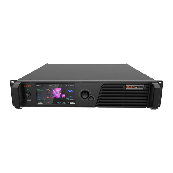
Page 5: Appearance
CX40 Pro LED Display Controller User Manual Appearance 2.1 Front Panel Name Description Running Indicator Solid red: Standby Solid blue: The device is being started. Solid green: The device is running normally. Flashing red: The device is running abnormally. - Page 6 CX40 Pro LED Display Controller User Manual Inputs Type Description HDMI 2.0-1 IN Resolutions Max resolution: 4096×2160@60Hz Min resolution: 800×600@60Hz Max width/height Max width: 8192 pixels (8192×1080@60Hz) (Forced) Max height: 8192 pixels (1080×8192@60Hz) Frame rates 23.98 / 24 / 25 / 29.97 / 30 / 47.95 / 48 / 50 / 59.94 / 60 / 71.93 / 72 / 75 / 100 / 119.88 / 120 / 143.86 / 144 / 240 Hz...
- Page 7 IN: Accept the sync signal. LOOP: Loop the sync signal. For standard Genlock signal generators, up to 20 CX40 Pro devices can be cascaded. An auxiliary port that connects to the central control device (RS232) (Reserved) Power 100-240V~, An AC power input connector and switch 50/60Hz, 1.5A...
-
Page 8: Applications
CX40 Pro LED Display Controller User Manual Applications The CX40 Pro has two typical applications. Application 1: Ethernet Output Application 2: Long-Distance Transmission via OPT Ports www.novastar.tech... -
Page 9: Ui Introduction
After the device is powered on, the home screen is displayed as follows, displaying device related information. The CX40 Pro is equipped with a touch LCD on which users can tap related areas to directly enter the corresponding settings page, making operating more convenient. - Page 10 CX40 Pro LED Display Controller User Manual Item Content Description The chassis fan speed Green: The fan speed is normal. Yellow: Fan speed alarm. The speed exceeded the threshold range. Yellow: Fan speed alarm. The speed exceeded the threshold range significantly.
-
Page 11: Main Menu
CX40 Pro LED Display Controller User Manual Item Content Description Dynamic Range The dynamic range of the currently processed signal SDR: Standard Dynamic Range HDR10: High Dynamic Range HLG: High Dynamic Range For the display control settings, please refer to 6.1.3 Set HDR Parameters... - Page 12 CX40 Pro LED Display Controller User Manual Module Description Set screen settings parameters, including enabling or disabling low latency and setting additional latency, setting bit depth, checking load status, selecting sync source, and setting sync phase offset. Provide the device diagnostics function, which is convenient for users to quickly check the device status, and check and export the diagnostic results.
-
Page 13: Screen Configuration
CX40 Pro LED Display Controller User Manual Screen Configuration 5.1 Set Input Source Select the desired input source and complete the related settings, such as resolution and frame rate. If the resolutions of the input source and screen are the same, the image can be displayed pixel to pixel. A lower frame rate may result in image flickering, while a higher frame rate helps stabilize the display image. -
Page 14: Free Screen Configuration In Vmp
Ethernet Port. Before configuring the screen, make sure that the cabinets have been connected to the output Ethernet ports. Run VMP and complete network settings in the CX40 Pro. On the home page, select Layout. Figure 5-2 Layout... - Page 15 CX40 Pro LED Display Controller User Manual In the device list on the left, select the desired controller. From the menu bar, choose View > Display, select a view for the topology area, and select the content to be displayed.
- Page 16 CX40 Pro LED Display Controller User Manual Figure 5-6 Cabinet connection For cabinets that have the same size and consecutive serial numbers, if you want to change the cabinet connection topology, select the cabinets and then select a quick topology under Quick topo in the properties area, as shown in Figure 5-7.
- Page 17 CX40 Pro LED Display Controller User Manual The drop-down menu of is shown in the figure below. The menu can be used to set the canvas grid. − Grid: When the switch is , a grid is displayed on the canvas. If you do not need to display the grid, click...
- Page 18 CX40 Pro LED Display Controller User Manual − Right click the cabinet Select String: Select all the cabinets on the connection line of the current cabinet. Switch: Switch the display areas of two cabinets. Group: Group the selected cabinets. To set the group name and color, please select the group and set them in the properties area.
-
Page 19: Display Effect Adjustment
CX40 Pro LED Display Controller User Manual Display Effect Adjustment 6.1 Set External Input Source Parameters 6.1.1 Check Input Source Information Check the attribute values of the input source, including the resolution, frame rate, bit depth, color gamut, etc. On the main menu screen, choose Input > Select Source to select an external video source (HDMI, DP or SDI). -
Page 20: Set Hdr Parameters (Hdmi Only)
CX40 Pro LED Display Controller User Manual Figure 6-3 EDID Select EDID and set the resolution and frame rate of the input source. Custom: Set the resolution manually. Listed standard resolutions: Select the desired resolution from the drop-down options. -
Page 21: Adjust Color
CX40 Pro LED Display Controller User Manual Note Using the HDR function reduces the CX40 Pro load capacity by less than half if the CX40 Pro works with the CA50E, CA50C and XA50 receiving cards. For details, see chapter 11 Ethernet Port Load Capacity. -
Page 22: Set Screen Color
CX40 Pro LED Display Controller User Manual Figure 6-6 Internal source Select a static picture or a motion picture. Set the parameters according to your actual needs; otherwise, please skip this step. Figure 6-7 Screen parameters After the settings are done, tap Apply. -
Page 23: Screen Settings
CX40 Pro LED Display Controller User Manual 6.4 Screen Settings 6.4.1 Set Low Latency The low latency function is used to reduce the latency at the controller, or increase the latency when the controller works with high-latency equipment. On the main menu screen, choose Screen Settings > Low latency. -
Page 24: Set Layer Scaling (All-In-One Controller Mode)
CX40 Pro LED Display Controller User Manual Figure 6-10 Sync Select the desired sync source from the listed ones. Active Source: Sync with the frame rate of the active source. Genlock: Sync with the frame rate of the Genlock signal. -
Page 25: Color Processing
6.6.1 Color Replacement Replace one color with another color according to the specified settings. This function only has an on/off switch on the CX40 Pro. You need to follow the steps below to set the specific parameters in VMP. Note Replacement of highly saturated colors is recommended for better effect. -
Page 26: 14Ch Color Correction
Support precise adjustment to hue, saturation and brightness of black, white and the 12 derived standard colors of the red, green and blue primary colors. This function only has an on/off switch on the CX40 Pro. You need to follow the steps below to set the specific parameters in VMP. -
Page 27: Curves Adjustment
Support adjustment to each of the image RGBW mapping curves. The precision is up to 12bit. This function only has an on/off switch on the CX40 Pro. You need to follow the steps below to set the specific parameters in VMP. -
Page 28: Enable 3D Lut
CX40 Pro LED Display Controller User Manual Figure 6-16 Curves Adjustment Select the white, red, green or blue channel. Drag the slider under the curve diagram to set the curve adjustment range. Click on any position of the curve to add an adjustment point and drag the point to adjust the curve. -
Page 29: Dynamic Booster
Figure 6-19 3D LUT 6.6.5 Dynamic Booster Note The Dynamic Booster function can be achieved when the CX40 Pro works with the CA50E, CA50C and XA50 receiving cards. Before operation, brightness correction by using the CA410-VP427, CA410-P427 or EYE2-400 color analyzer is recommended. -
Page 30: Apply Presets
The CX40 Pro supports applying the presets only. To save a preset, follow the steps below in VMP. Save Presets After completing the screen configuration and display effect adjustment, you can save the data on the Source, Layout, Processing and Screen Settings pages as a preset so that these data can be directly applied in the future. - Page 31 CX40 Pro LED Display Controller User Manual Figure 6-22 Saving presets Click a preset icon. In the properties area, set a name for the preset and select the data you need to save. If the preset you selected is not a blank one, the original data will be overwritten.
-
Page 32: Device Management
When the device is powered on, a self-test is performed automatically. Startup OK: You can start using the full functionality of the CX40 Pro. Startup error: The following error information is displayed. If you select Close, you will use the device in the function restricted state. -
Page 33: Set An Ip Address
CX40 Pro LED Display Controller User Manual Figure 7-3 Diagnostics Select Yes in the displayed dialog box. After successful diagnostics, do any of the following as required. Check the diagnostic result Check the diagnostic result report, including the supply voltages of the MCU, FPGA and motherboard, the temperature inside the chassis, and other information. -
Page 34: Check The Firmware Version
CX40 Pro LED Display Controller User Manual Figure 7-5 Factory reset Do any of the following according to the data you want to reset. Reset part of the data Reset all the data except the imported files, network parameters, language settings, and device name. -
Page 35: System Settings
CX40 Pro LED Display Controller User Manual System Settings 8.1 Switch Working Mode Switch the device working mode to All-In-One Controller or Send-Only Controller. On the main menu screen, choose Settings > Working Mode. Figure 8-1 Working Mode Select All-In-One Controller or Send-Only Controller. -
Page 36: Set Lcd Brightness
CX40 Pro LED Display Controller User Manual Figure 8-3 Enable Screen Saver Select 1min, 5min, 30min, 1hour or Never from the drop-down options as needed. 8.4 Set LCD Brightness Set the LCD brightness of the device according to the on-site conditions. -
Page 37: Set Temperature Scale
CX40 Pro LED Display Controller User Manual Choose 中文 or English as required. 8.6 Set Temperature Scale Change the temperature scale of the device. On the main menu screen, choose Settings > Temp Scale. Figure 8-6 Temperature scale Choose ° C or ° F as required. -
Page 38: Product Specifications
CX40 Pro LED Display Controller User Manual Product Specifications Electrical Power supply AC 100-240V~, 50/60Hz, 1.5A Specifications Power consumption 105 W Operating –10º C to +45º C Temperature Environment Humidity 0% RH to 80% RH, non-condensing Storage –30º C to +80º C... -
Page 39: Video Source Specifications
CX40 Pro LED Display Controller User Manual Video Source Specifications Input Bit Depth Color Space/Sampling Max Input Resolution HDMI 2.0-1 8bit RGB 4:4:4 4096×2160@60Hz 8192×1080@60Hz YCbCr 4:4:4 YCbCr 4:2:2 10bit/12bit RGB 4:4:4 4096×2160@30Hz 4096×1080@60Hz YCbCr 4:4:4 YCbCr 4:2:2 4096×2160@60Hz HDMI 2.0-2... -
Page 40: Ethernet Port Load Capacity
CX40 Pro LED Display Controller User Manual Ethernet Port Load Capacity When the CX40 Pro works with the CA50E, CA50C and XA50 receiving cards, the formula of calculating the load capacity per Ethernet port and the detailed parameters are as follows.
Need help?
Do you have a question about the CX40 Pro and is the answer not in the manual?
Questions and answers