Table of Contents
Advertisement
Quick Links
Advertisement
Table of Contents

Related Manuals for NovaStar VC16


Summary of Contents for NovaStar VC16
- Page 1 VC16 All-in-One Controller User Manual...
-
Page 2: Change History
VC16 All-in-One Controller User Manual Change History Change History Document Version Release Date Description V1.0.0 2024-07-09 First release www.novastar.tech... -
Page 3: Table Of Contents
VC16 All-in-One Controller User Manual Contents Contents Change History ..................................i Contents ....................................ii Overview ....................................1 Introduction.................................. 1 Features ..................................1 Appearance ..................................4 Front Panel ................................... 4 Rear Panel ..................................5 Applications ..................................9 Home Screen ..................................10 Menu Operations ................................ - Page 4 Factory Reset ..............................46 Communication Settings ............................46 Language .................................. 47 About ..................................47 Specifications ................................... 48 Video Source Feature ..............................49 A Instructions for the 3D Function ..........................50 A.1 For a Single VC16 Unit ............................50 A.2 Notes .................................... 51 www.novastar.tech...
-
Page 5: Overview
The VC16 is NovaStar's new all-in-one controller that integrates video processing and video control into one box. It features 16 Ethernet ports. A VC16 unit can drive up to 10.4 million pixels, with the maximum output width and height up to 16,384 pixels and 8192 pixels respectively, which is ideal for on-site extra-wide and extra-high LED screen control applications. - Page 6 VC16 All-in-One Controller User Manual 1 Overview Personalized image scaling Powerful video processing Supports three kinds of image Based on SuperView III image − scaling modes, including full screen, quality processing technologies pixel to pixel and custom. to provide stepless output scaling.
- Page 7 VC16 All-in-One Controller User Manual 1 Overview Import and export EDID files allowing for better image quality. The function of displaying image on Display the MAC address on the screen for test is also supported. device LCD screen.
-
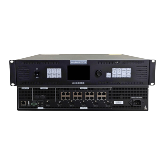
Page 8: Appearance
VC16 All-in-One Controller User Manual 2 Appearance Appearance Front Panel Button Description Power switch Power on or power off the device. When the window is closed, press the button to open the window and enter Window the corresponding window settings screen. -
Page 9: Rear Panel
VC16 All-in-One Controller User Manual 2 Appearance Off: The input source is not accessed. Note: On the home screen, when window 1 is opened, you can press the input source button to quickly switch the input source for window 1. - Page 10 VC16 All-in-One Controller User Manual 2 Appearance 1920×1080@24/25/30/48/50/60Hz 3840×1080@30/50/60/120Hz 2560×1600@50/60/120Hz 3840×2160@24/25/30/50/60Hz 4096×2160@30/60Hz 7680×1080@30/60Hz 8192×1080@30/60Hz Does NOT support interlaced signal inputs. DP 1.2 1x DP 1.2 Max. input resolution: 4K×2K@60Hz or 8K×1K@60Hz Custom resolutions supported Max. width: 8192 pixels Max.
- Page 11 VC16 All-in-One Controller User Manual 2 Appearance Supported standard resolutions: 1366×768@50/60Hz 1920×1080@24/25/30/48/50/60Hz Does NOT support interlaced signal inputs. 3G-SDI 1x 3G-SDI (optional) ST-424 (3G), ST-292 (HD) and ST-259 (SD) standard video inputs supported Max. input resolution: 1920×1080@60Hz ...
- Page 12 VC16 All-in-One Controller User Manual 2 Appearance rate: 120Hz) Note: Ethernet ports 1 and 2 support audio output. When you use a multifunction card to parse the audio, be sure to connect the card to Ethernet port 1 or 2.
-
Page 13: Applications
VC16 All-in-One Controller User Manual 3 Applications Applications www.novastar.tech... -
Page 14: Home Screen
VC16 All-in-One Controller User Manual 4 Home Screen Home Screen Figure 4-1 Home Screen Area Icon Meaning The device name The device IP address Hold down the knob and ESC button simultaneously to lock or unlock the front panel buttons. - Page 15 The test pattern is shown. The output image is displayed. The output image is frozen. Communication The VC16 is communicating with the control PC via LAN. The VC16 is not connected to the control PC. The 3D function is turned on.
-
Page 16: Menu Operations
VC16 All-in-One Controller User Manual 5 Menu Operations Menu Operations Note: Knob: On the home screen, press the knob to enter the main menu screen. On the main menu screen, rotate the knob to select a menu item, and press the knob to confirm the selection or enter the submenu. -
Page 17: Input Settings
VC16 All-in-One Controller User Manual 5 Menu Operations Input Settings Input Source Selection The supported input sources include HDMI 2.0, DP 1.2, HDMI 1.3 and 3G-SDI (optional). Rotate the knob to select the desired input source and press the knob to enter the input source resolution setting screen. - Page 18 VC16 All-in-One Controller User Manual 5 Menu Operations Figure 5-3 Standard resolution Table 5-1 Standard resolutions Standard Resolution DP 1.2 HDMI 2.0 HDMI 1.3 1024×768@(48/50/60/75/85)Hz √ √ √ 1280×720@(24/25/30/48/50/60)Hz √ √ √ 1280×1024@(48/50/60/75/85)Hz √ √ √ 1364×768@(50/60)Hz √ 1366×768@(50/60)Hz √...
-
Page 19: Rgb Limited To Rgb Full
Figure 5-4 Custom resolution RGB Limited to RGB Full The VC16 can automatically convert the color space of the video source from RGB limited to RGB full, allowing for more accurate video processing. Off: Don’t convert the color space of the current video source from RGB limited to RGB ... -
Page 20: Window Settings
VC16 All-in-One Controller User Manual 5 Menu Operations Window Settings The VC16 supports 2x 4K×2K+4x 2K×1K windows which can be arranged as you wish and you can also set the window parameters as described in the following table. Table 5-2 Window parameters... -
Page 21: Add Windows
VC16 All-in-One Controller User Manual 5 Menu Operations Add Windows Button Operations Step 1 Press the window button in the WINDOWS area on the device front panel to quickly open the Window and the device screen displays the corresponding Window settings screen. -
Page 22: Switch Window Input Sources
VC16 All-in-One Controller User Manual 5 Menu Operations Figure 5-6 Window parameter descriptions Step 7 Rotate the knob to select Priority and set the Window z-order. Switch Window Input Sources Button Operations Step 1 Press the desired window button in the WINDOWS area on the device front panel to quickly open the Window and the device screen displays the corresponding Window settings screen. - Page 23 VC16 All-in-One Controller User Manual 5 Menu Operations Notes: On the home screen, when window 1 is opened, you can press the input source button to quickly switch the input source for window 1. Press the SCALE button to make the bottom Window fill the whole screen quickly.
-
Page 24: Bkg Settings
Figure 5-9 Input crop effect Input Source: 1920×1080@60Hz Window Size: 1920×1080 BKG Settings The VC16 supports BKG settings. On the Window Settings screen, rotate the knob to select BKG Settings and press the knob to enter the BKG Settings screen. Menu Description... -
Page 25: Osd Settings
The BKG has the lowest priority and its priority cannot be changed. OSD Settings The VC16 supports at most 6 OSD. Each time only one OSD can be used. OSD has the highest priority which cannot be changed. Before you add OSD, please make sure you have imported the OSD images or edited the OSD text in V-Can. -
Page 26: Display Control
VC16 All-in-One Controller User Manual 5 Menu Operations Parameter Description The value ranges from 0 to 16384. Initial Y The initial vertical coordinate of the OSD The value ranges from 0 to 8192. Notes: You cannot adjust the OSD size via the device front panel screen. If you do need to resize the OSD, please adjust it when you import it in V-Can. -
Page 27: Preset Settings
A preset is a set of parameters that save the Window and Window-related information. The VC16 supports ten user-defined presets. After a preset is saved, you can load the preset simply by its name. The preset operations include Save, Load, Clear and Copy To. -
Page 28: Load Presets
VC16 All-in-One Controller User Manual 5 Menu Operations Step 3 Rotate the knob to select Save and press the knob to save the Window settings to this preset. After a preset is saved, the preset status on the right side changes to Saved. -
Page 29: Advanced Settings
5 Menu Operations Advanced Settings Device Backup The VC16 supports both the backup between devices and Ethernet ports. Backup Between Devices Device backup allows you to set the backup relationship between two devices. You can set one of the devices as the primary device or the backup device. When the primary device... - Page 30 VC16 All-in-One Controller User Manual 5 Menu Operations Figure 5-15 Device Backup Step 2 Rotate the knob to select Set as Primary. Follow the same procedure to set the other device as backup. Notes: In the device backup mode, the quantity of the cabinets loaded by each Ethernet port on both the primary and backup devices must be the same, but their data flow must be in a reversed way.
- Page 31 VC16 All-in-One Controller User Manual 5 Menu Operations The connection diagram for the Ethernet port backup: Figure 5-16 Ethernet port backup connection The setting procedure for the Ethernet port backup: Step 2 Run the NovaLCT software. On the menu bar, go to User > Advanced Synchronous System User Login.
- Page 32 VC16 All-in-One Controller User Manual 5 Menu Operations Figure 5-17 Screen configuration Step 5 Select the Sending Card tab, and then click Add in the Redundancy area. Step 6 Set the serial numbers of both the primary device and backup device to 1.
-
Page 33: Ethernet Port Backup Test
Step 11 Click Save to save the backup parameters to the sending and receiving cards respectively. Ethernet Port Backup Test The VC16 supports the Ethernet port backup test. You can test whether the pre-stored images, backup Ethernet ports and devices take effect without plugging and unplugging the Ethernet cables. -
Page 34: Input Backup
VC16 All-in-One Controller User Manual 5 Menu Operations Figure 5-20 Ethernet port backup test Input Backup Input backup allows you to set the backup relationship between two input sources. When one input source has a problem or the input connector fails, the backup source will be used seamlessly and continue to work well to ensure the LED screen will not go black. -
Page 35: Synchronization
VC16 All-in-One Controller User Manual 5 Menu Operations Not supported backup groups HDMI 2.0 and HDMI 1.3 sources − DP 1.2 and HDMI 1.3 sources − In each backup group, the two input sources serve as the backup for each other. -
Page 36: Screen Configuration
Step 3 Rotate the knob to select Source and press the knob to confirm. Then rotate the knob again to select the desired sync source. Note: If two or more VC16 units load an LED screen, the sync sources used by each device must be the same. Screen Configuration... - Page 37 VC16 All-in-One Controller User Manual 5 Menu Operations Quick Configuration When the LED screen is a regular one composed of cabinets from the same batch, you can use the quick configuration function to configure the LED screen. Prerequisites The LED screen must be a regular one.
- Page 38 VC16 All-in-One Controller User Manual 5 Menu Operations Notes: Cabinets loaded by Ethernet port 1 ≥ cabinets loaded by Ethernet port 2 ≥ ... ≥ cabinets loaded by Ethernet port 24 The number of cabinets loaded by each Ethernet port must be an integer multiple of Cabinet Row ...
- Page 39 VC16 All-in-One Controller User Manual 5 Menu Operations Step 2 Go to Tools > Controller Cabinet Configuration File Import to enter the controller cabinet configuration file importing page. Figure 5-27 Import cabinet configuration file Step 3 Click Add Configuration File and select the desired file from the window that appears.
- Page 40 The receiving cards that are connected to the device must support the Mapping function. For the supported models of the receiving cards, please visit our official website at www.novastar.tech. On the main menu screen, go to Advanced Settings > Screen Configuration > More Settings >...
- Page 41 VC16 All-in-One Controller User Manual 5 Menu Operations Figure 5-29 Mapping P:05 indicates the Ethernet port number of the sending device. #001 shows the number of the cabinet loaded by the Ethernet port. LED Screen Color This function allows you to adjust the color temperature and Gamma value of the LED screen to make the images displayed on the screen more clear and vivid.
-
Page 42: Audio
VC16 All-in-One Controller User Manual 5 Menu Operations Figure 5-30 LED screen color Table 5-5 LED color parameter descriptions Parameter Description Gamma Adjust the image distortion degree from the input to output. The greater the value is, the more distorted the image will be. - Page 43 VC16 All-in-One Controller User Manual 5 Menu Operations Figure 5-31 Audio output connection-1 Via the audio output connector Connect the audio output connector to an external speaker. Figure 5-32 Audio output connection-2 On the main menu screen, go to Advanced Settings > Audio to enter the audio settings screen.
- Page 44 VC16 All-in-One Controller User Manual 5 Menu Operations Figure 5-33 Audio settings Output Set to play which audio on the external speaker. Step 1 On the audio settings screen, rotate the knob to select Output. Step 2 Press the knob to open the available output list and rotate the knob to select where the output audio is from.
- Page 45 VC16 All-in-One Controller User Manual 5 Menu Operations On the audio settings screen, rotate the knob to select Volume and press the knob to confirm. Then rotate the knob again to adjust the audio volume and press the knob to confirm.
-
Page 46: Advanced Functions
VC16 All-in-One Controller User Manual 5 Menu Operations Audio In: Play the audio from the audio output connector for the SDI input source. − Step 4 Rotate the knob to select the desired audio and press the knob to confirm. - Page 47 When HDR function is enabled, the output loading capacity will be reduced by 50%. The VC16 can work with the EMT200 3D emitter and 3D glasses to provide you with a 3D visual experience. For detailed operations, please refer to A Instructions for the 3D Function.
- Page 48 VC16 All-in-One Controller User Manual 5 Menu Operations Step 1 Complete the hardware connections as shown in Figure 5-38 Step 2 Press the knob to enter the main menu screen. Step 3 Rotate the knob to select Advanced Settings > Advanced Functions > 3D to turn on the function.
-
Page 49: Output Frame Rate
VC16 All-in-One Controller User Manual 5 Menu Operations Notes: Only window 1 supports the 3D function. Turning on the 3D function will halve the device output capacity. To enable pixel-to-pixel display of a 3D video source, set the Window width to the ... -
Page 50: Return To Home (S)
VC16 All-in-One Controller User Manual 5 Menu Operations Return to Home (s) You can set the period when the system stays at the current screen before returning to the homepage automatically when there is no operation performed. The value ranges from 60s to 3600s. -
Page 51: Language
VC16 All-in-One Controller User Manual 5 Menu Operations Figure 5-42 Communication settings Step 2 Select Mode and press the knob to confirm. The options include Manual and Automatic. Manual: Set the device IP address, subnet mask and gateway manually. ... -
Page 52: Specifications
VC16 All-in-One Controller User Manual 6 Specifications Specifications Overall Specifications Power AC100V~240V, 2~0.8A, 50/60Hz Electrical connector Specifications Power 50 W consumption Temperature 0°C to 50°C Operating Environment Humidity 0% RH to 80% RH, non-condensing Temperature –20°C to +60°C Storage Environment... -
Page 53: Video Source Feature
VC16 All-in-One Controller User Manual 7 Video Source Feature Video Source Feature Input Connectors Bit Depth Max. Input Resolution HDMI 2.0 8bit RGB4:4:4 3840×2160@60Hz YCbCr4:4:4 YCbCr4:2:2 YCbCr4:2:0 10bit/12bit RGB4:4:4 3840×2160@30Hz YCbCr4:4:4 YCbCr4:2:2 3840×2160@60Hz YCbCr4:2:0 DP 1.2 8bit RGB4:4:4 3840×2160@60Hz YCbCr4:4:4... -
Page 54: A Instructions For The 3D Function
For a Single VC16 Unit Step 1 Select a 3D video source and connect it to the DP or HDMI connector of the VC16 unit. Step 2 Connect the VC16 unit to the EMT200 3D emitter and the LED screen in series via Ethernet cables. -
Page 55: Notes
3D effect will not be affected at all. Notes 1. Turning on the 3D mode halves the loading capacity of each Ethernet port and the VC16 unit. 2. It is recommended you stay at most 3 meters away from the EMT200 when using the 3D glasses.
Need help?
Do you have a question about the VC16 and is the answer not in the manual?
Questions and answers