
Subscribe to Our Youtube Channel
Related Manuals for NovaStar C1


Summary of Contents for NovaStar C1
- Page 1 Event Controller User Manual Document Version: V1.0.3 Document Number: NS160100440...
- Page 2 Xi’an NovaStar Tech Co., Ltd. Statement You are welcome to use the product of Xi’an NovaStar Tech Co., Ltd. (hereinafter referred to as NovaStar). This document is intended to help you understand and use the product. For accuracy and reliability, NovaStar may make improvements and/or changes to this document at any time and without notice.
-
Page 3: Table Of Contents
4.4.1 Device Status ........................41 4.4.2 Program Update ......................... 42 4.4.3 USB Import and Export ....................... 43 4.4.4 Communication Settings ..................... 44 4.4.5 Language ..........................44 4.4.6 Restoring Factory Settings ....................45 4.4.7 Self-Test ..........................46 4.4.8 Manufacturer Information ....................46 www.novastar.tech... -
Page 4: Introduction
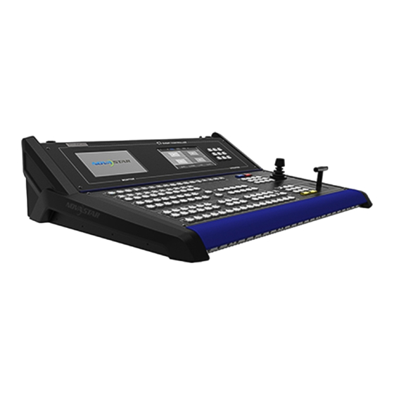
The C1 is an event controller of NovaStar specifically designed for video processing products and mainly used for live stage control. The C1 is designed with 2 LCD screens. One is used to monitor input sources. The other, together with buttons on the panel, is used to configure the layer size, layer position, input source, output resolution, layer border and input cropping. -
Page 5: Hardware Introduction
User Manual 2 Hardware Introduction Hardware Introduction Note Button operations mentioned in this document are as follows. Press: Press and immediately release the button. Hold down: Press and hold the button for 3 seconds or longer. 2.1 Appearance www.novastar.tech... -
Page 6: Front Panel
2.2 Front Panel LCD Screens The C1 is designed with 2 LCD screens for monitoring and operation configuration. The monitor screen on the left is used to monitor the input sources, PVW and PGM. You can view the input source content, real-time editing content in PVW, and current playback contents in PGM. - Page 7 CLONE: Press this button to copy a layer. Press a layer button, or select a layer on the right LCD screen and then − press CLONE button to clone a layer for the selected layer. The size of the www.novastar.tech...
- Page 8 − MAIN: Press this button to enter the programming page. PGM/PVW: Press this button to select PGM and hold down the button to select PVW. This button mainly works with the CAPTURE button to capture an image www.novastar.tech...
- Page 9 PGM or PVW, or works with the AUX button to set the PGM or PVW as the source of AUX output. Preset The C1 supports up to 32 presets. When a preset is selected by pressing the corresponding preset button, the button turns green. Figure 2-5 Preset selection buttons ...
- Page 10 DELETE CUSTOM together to delete all the custom presets at once. Layer The C1 supports up to 8 layers and 1 BKG. The layer buttons represent the numbers of the layers. When you press one of those buttons, the corresponding layer is selected and the button turns green.
- Page 11 Green: The input source is being used. Yellow: The input source is accessed to the device connected to the C1, but the source is not used. Off: No input source is accessed or the input source is abnormal.
- Page 12 The layer will fill the entire mosaic screen where the layer belongs to. H/V: Press this button to select the direction of adjusting a layer by using the joystick. After pressed, the button turns green. When you have fished the www.novastar.tech...
- Page 13 Transition The transition effect buttons in this area will turn green if they are pressed. Other buttons will turn green after they are pressed and then the button lights go back to normal status after the buttons are released. www.novastar.tech...
-
Page 14: Rear Panel
2. AC 100-240 V–50/60 Hz: AC power input 3. ETHERNET: An Ethernet port connecting to a device to be controlled by the 4. USB: A type-B USB port connecting to an upper computer to update the C1 program 5. U-DISK: A type-A USB port connecting to a USB drive to upgrade the C1 program and import the BKG files 6. - Page 15 Monitor LOOP: An HDMI-type monitoring loop output connector that connects to the monitoring connector of the device controlled by the C1. The C1 receives the input signal from the device and send the signal to another monitor. 8. RESET: A pinhole reset button used to restart the C1...
-
Page 16: Applications
User Manual 3 Applications Applications Note Note: The device must be powered off before connection. Figure 3-1 Application scenario www.novastar.tech... -
Page 17: Operations
Figure 4-1 Operation flowchart 4.1 Preparation Use an Ethernet cable to connect the controlled device to the C1 through Ethernet ports and then set IP address of the device (taking the N9 for example). www.novastar.tech... -
Page 18: Configuration
4 Operations Figure 4-2 Setting IP address of controlled device Set the IP address of the C1 and make sure the C1 and the N9 are on the same network segment. To set the IP address, choose Menu > Settings >... - Page 19 Step 2 On the touch operation panel, select the device to be added and then click Add. Figure 4-5 Adding devices After the devices are added, you can view the information of those added devices on the Device List page, as shown in the figure below. www.novastar.tech...
-
Page 20: Configuring Device Properties
Figure 4-6 Device list Note: The C1 automatically groups the added devices. Up to 50 devices can be found and up to 16 devices can be added. On device list page, tap the removing button (icon) to select the devices to be removed, and then tap the button again to remove the selected devices. -
Page 21: Input
VE7, the input sources from the VE7 will be displayed on the N9 with an Ex in front of each input source name. Step 1 Click Input to enter the list of connectors. Figure 4-8 Input source selection www.novastar.tech... - Page 22 Basic properties include source type, slot No., resolution and connector capacity. This is for viewing basic information of current connector. − Connector capacity: Denotes the level of resolution, including SL, DL and 4K. SL denotes 1920×1080, DL denotes 3840×1080, and 4K denotes 3840×2160. www.novastar.tech...
- Page 23 1920×1200, 1920×2160, 2048×640, 2048×1152, 2048×1536, 2304×1152, 2560×816, 2560×960, 2560×1600, 3840×1080, 3840×1600, 3840×2160 Standard refresh rates: 60Hz, 75Hz, 120Hz Figure 4-11 Standard EDID You can drag the sliders, tap the + or – button, or enter numbers to customize EDID. www.novastar.tech...
- Page 24 On the Input Color page, you can adjust the overall brightness, contrast, saturation and hue of the input source by dragging the sliders, tapping the + or – button, or entering numbers. When you tap Reset, parameters on this page can be reset to the default value 50. www.novastar.tech...
-
Page 25: Output
4 Operations Figure 4-13 Input color adjustment 4.2.2.2 Output Output settings allow you to view the information of output connectors, set output resolution, adjust output image quality, set test pattern and synchronization mode. Figure 4-14 Output settings Output connectors www.novastar.tech... - Page 26 This includes settings of resolution and refresh rate. You can either choose a standard resolution and refresh rate, or customize them. The standard resolutions and refresh rates are predefined in the C1.You can also drag the sliders, tap the + or – button, or enter numbers to customize a resolution and refresh rate.
- Page 27 On the Output Color page, you can adjust the overall brightness, contrast, saturation and hue of the output by dragging the sliders, tapping the + or – button, or entering numbers. When you tap Reset, parameters on this page can be reset to the default value 50. www.novastar.tech...
- Page 28 Test Pattern On this page, you can tap to expand the test pattern list to choose a test pattern. After you tap the Normal button in the settings area, the LED display will go back to normal display. www.novastar.tech...
- Page 29 You can choose either an input source or the Genlock source as the synchronous source. When you choose the former, current synchronous mode is internal synchronization. When you choose the latter, current synchronous mode is external synchronization. www.novastar.tech...
-
Page 30: Fast Mosaic
4.2.2.3 Fast Mosaic The C1 supports fast mosaic. By entering the screen width and height, the system will come up with a mosaic plan automatically. Step 1 Tap > next to Fast Mosaic to enter the fast mosaic page. -
Page 31: Advanced Mosaic
This mosaic mode allow you to select a proper mosaic mode according to the screen size. Step 1 Tap the drop-down box next to Mosaic Mode and choose a mosaic mode from the drop-down list. Mosaic mode: 1×1, 1×2, 2×1, 2×2, 1×3, 3×1, 1×4, 4×1 Step 2 Tap Next. www.novastar.tech... - Page 32 Advanced Mosaic page. Step 3 Select a mosaic screen and drag the sliders, tap the + or – button, or enter numbers to adjust the width and height of the mosaic screen. After adjustment, tap Apply. Figure 4-23 Adjusting mosaic screen www.novastar.tech...
-
Page 33: Programming
The programming function allows you to edit and clone a layer, save, load and clear preset data, set transition effects and BKG. Note: For the functions not supported by the device connected to the C1, the function buttons on the C1 will be unavailable. 4.3.1 Layer Adding Layers Step 1 Tap Programming to enter the programming page. - Page 34 LAYER area on the front panel or tapping a layer on the touch operation screen. After the layer is selected, tap Clear to clear the layer. Modifying Layer Properties To modify layer properties, on the tool bar of the programming page, choose Layer Settings > Properties to enter the layer properties page. www.novastar.tech...
- Page 35 To enter the Layer Color page, tap the Layer Color option or press the LAYER COLOR button in the LAYER area on the front panel. On this page, you can set the overall brightness or RGB brightness, contrast, saturation and hue. www.novastar.tech...
- Page 36 Input Crop option to enter its page and tap the toggle button. Or, press the CROP ON/OFF button in the LAYER area on the front panel. Then, you can adjust the width, height, X, and Y parameters to set the area to be cropped. www.novastar.tech...
-
Page 37: Transition Effects
13 effects. On the Effects page, you can tap < or > button to view the effects. After you tap an effect icon to select it, tap the drop-down box next to Time to set the transition duration. Value ranges: 0–2 seconds www.novastar.tech... -
Page 38: Bkg
Step 1 Insert the USB drive which stores images into the type-A USB port on the rear panel of the C1. Step 2 After the C1 identified the USB files automatically, a file import prompt box will be displayed. Tap Import in the box. The system will import the stored images to the C1. - Page 39 Figure 4-29 BKG settings Read: Read the information of the BKG files added by the controlled device and send the information to the C1. Load: Add the imported images to the BKG. Step 6 Tap Apply or press the APPLY button in the OPERATION area to apply the BKG file to PVW to PGM.
-
Page 40: Presets
A white preset name denotes the preset is blank and no layer data is saved in it. Saving Presets The C1 allows the edited PVW or PGM to be saved as a preset which can be loaded and applied directly. - Page 41 User Manual 4 Operations Figure 4-30 Saving presets Loading Presets The C1 allows custom presets and preset templates to be applied directly. Custom presets can be loaded on the LCD screen and preset templates can be applied with buttons. ...
-
Page 42: Aux
Tap Clear to clear the layers and BKG information in the editing area. 4.3.5 AUX The C1 supports up to 3 AUX configuration. Press the AUX button in the FCUNCTION area or tap AUX on Programming page to enter the AUX settings page as shown in the figure below. -
Page 43: Capturing
User Manual 4 Operations 4.3.6 Capturing The C1 allows you to capture the input sources and the captured images can be saved as BKG. In the FUNCTION area, hold down the Capture button, and it flashes green. Press the button of the input source you want to capture to capture its current frame. The Capture screen is displayed after capturing. -
Page 44: Device Status
User Manual 4 Operations Figure 4-34 Settings 4.4.1 Device Status Tap Device to view the temperature and voltage of the device. www.novastar.tech... -
Page 45: Program Update
The C1 can be updated via USB. You can save the update program file in a USB drive and insert it into the USB port on the rear panel of the C1. On the Program Update screen, tap Program Update. The system automatically searches the USB drive for the update program file and a pop-up window appears. -
Page 46: Usb Import And Export
Configuration files saved in a USB drive can be imported into the C1 and configuration files in the C1 can be exported to a USB drive so that the files can be imported into another C1 unit for quick use. -
Page 47: Communication Settings
Tap USB Import, the system will automatically import the configuration files into the C1. USB Export Insert a USB drive into the USB port on the rear panel of the C1. Choose Settings > USB Import and Export to enter the USB import and export screen. -
Page 48: Restoring Factory Settings
Figure 4-40 Language 4.4.6 Restoring Factory Settings The C1 allows itself as well as its controlled devices to be restored to factory settings. You can choose Restore Factory and Restore (Save IP), and choose to restore the terminal device to factory settings. -
Page 49: Self-Test
Figure 4-41 Restoring factory 4.4.7 Self-Test Test whether each component can work normally. If anything is wrong, please feedback to technical support team of Xi’an NovaStar Tech Co., Ltd. to solve the problem as soon as possible. 4.4.8 Manufacturer Information You can view the manufacturer information of the C1, including the official website and QR code. - Page 50 User Manual 4 Operations Figure 4-42 Manufacturer information www.novastar.tech...
Need help?
Do you have a question about the C1 and is the answer not in the manual?
Questions and answers