Table of Contents
Advertisement
Quick Links
ADV7611/ Eval Note
Eval Note
Evaluation Note
ADV7611 Evaluation
Board Rev. B
October 2010
Pr. A
Pr.A
Information furnished by Analog Devices is believed to be accurate and reliable. However, no
responsibility is assumed by Analog Devices for its use, nor for any infringements of patents or
other rights of third parties that may result from its use. Specifications subject to change without
notice. No license is granted by implication or otherwise under any patent or patent rights of
Analog Devices. Trademarks and registered trademarks are the property of their respective
owners.
Advertisement
Table of Contents

Subscribe to Our Youtube Channel
Related Manuals for Analog Devices Advantiv EVAL-ADV7611EB1Z


Summary of Contents for Analog Devices Advantiv EVAL-ADV7611EB1Z
- Page 1 Information furnished by Analog Devices is believed to be accurate and reliable. However, no responsibility is assumed by Analog Devices for its use, nor for any infringements of patents or other rights of third parties that may result from its use. Specifications subject to change without notice.
-
Page 2: Table Of Contents
Eval Note Table of Contents Table of Contents ............................2 Introduction ............................3 Evaluation Kit ............................3 Initial Hardware Configuration ......................4 Initial Hardware Configuration ......................5 XRC Installation ..........................5 ... -
Page 3: Introduction
Eval Note 1. Introduction This evaluation note is intended to provide application support for the ADV7611 evaluation board. It also provides details on the set up and manual configuration of the evaluation board. Software drivers are available for this evaluation board - a separate user guide is available for these software drivers. This note applies to board revision B. -
Page 4: Initial Hardware Configuration
Eval Note 3. Initial Hardware Configuration The ADV7611 evaluation board is a standalone evaluation platform used to demonstrate all features of the ADV7611 receiver. To assemble the platform, connect the female connector of the 7.5V DC power supply module supplied with the evaluation kit to the motherboard power connector, J8. To turn the evaluation platform on, flick the power switch (S5) to position “ON”. -
Page 5: Initial Hardware Configuration
Eval Note 4. Initial Hardware Configuration 4.1 XRC Installation Run ADI_Install_XRC_x file (where x is the version number to be installed e.g. 1.5) Review the license agreement and click “I Agree” if the terms of the agreement are acceptable Select the desired access links – desktop shortcut and/or start menu shortcut (see Figure 2) Figure 2 - Installation Options Press “Next>”... -
Page 6: Loading/Unloading Boards
Eval Note 4.2 Loading/Unloading Boards 4.2.1 Loading a Board The following steps must be performed to start a new XRC session by loading a new board. Click “Choose Board…” From the Board Selector window, select your attached system e.g. “ADV7611” as RX, “None” for MotherBoard and “ADV7511_ADV7341”... -
Page 7: Running Scripts
Eval Note 4.3 Running Scripts Scripts can be run by either of the following options: Select Scripts -> Project Name e.g. ADV7611 Follow the script tree as outlined in the expanding menus (see Figure 5) Select Scripts -> Run Script Open the script folder of the desired project Select the desired script and click “Open”... -
Page 8: Other Xrc Features
Eval Note 4.4 Other XRC Features 4.4.1 Register Control The following steps must be performed to use XRC Register Control: Select Tools -> Register Control Enter the Device Address in HEX (see Figure 6) Enter the desired register address in HEX Press the “Write”... -
Page 9: The Adv7611 Evaluation Platform In Depth
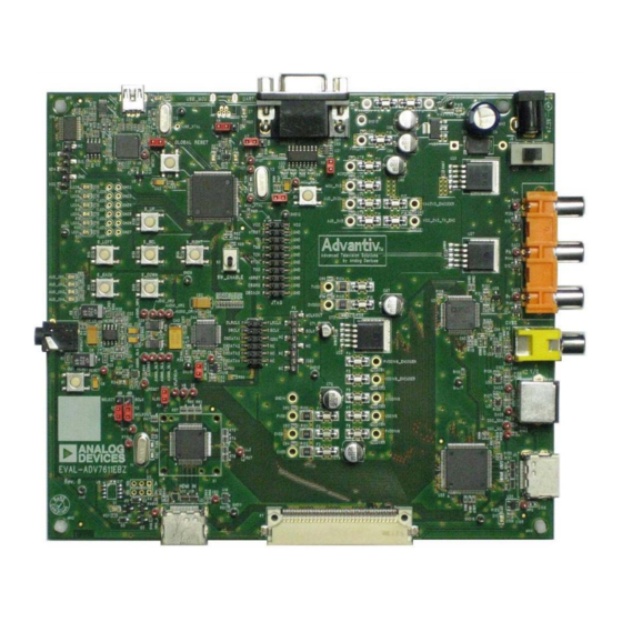
Eval Note 5. The ADV7611 Evaluation Platform in Depth 5.1 Hardware Overview The following features of the ADV7611 evaluation board should be noted 5.1.1 Connectors 1 x HDMI inputs (J2) 1 x HDMI output (J9) 1 x UART connector (J7) 1 x USB connector (J1) 1 x audio output (U58) 1 x S-video output (p5) - Page 10 Eval Note POWER RS-232 SUPPLY ADV7341 YPrPb OUTPUT ADV7341 AUDIO OUTPUT ADV7611 ADV7511 HDMI OUTPUT Figure 7 – ADV7611 Evaluation Platform HDMI INPUT Rev. PrA Page 10 of 31...
-
Page 11: Using The Adv7611 Evaluation Platform
Eval Note 5.2 Using the ADV7611 Evaluation Platform 5.2.1 Connecting an Input Video Source To connect an input video source to the ADV7611 evaluation board, use a HDMI cable and the input HDMI connector; J2. Do not use excessive force when connecting or disconnecting the cable as this may result in damage to the evaluation board. -
Page 12: Interfacing With The Software Driver
Eval Note 5.2.6 Interfacing with the Software Driver Jumper K8, when inserted, pulls the microcontroller reset low. To use the software driver, please ensure that K8 is removed. To stop and start the software driver (e.g. to allow access to the I2C over XRC), toggle the SW_ENABLE switch on the evaluation board. -
Page 13: Appendix 1 - Schematics
Eval Note 6. Appendix 1 – Schematics Figure 8 HDMI Inputs Schematics Page Rev. PrA Page 13 of 31... - Page 14 Eval Note Figure 9: USB + Reset Circuitry Schematics Page Rev. PrA Page 14 of 31...
- Page 15 Eval Note Figure 10: ADV7611 Schematics Page Rev. PrA Page 15 of 31...
- Page 16 Eval Note Figure 11: Power Schematics Page 1 of 2 Rev. PrA Page 16 of 31...
- Page 17 Eval Note Figure 12: Power Schematics Page 2 of 2 Rev. PrA Page 17 of 31...
- Page 18 Eval Note Figure 13: Microcontroller Schematics Page Rev. PrA Page 18 of 31...
- Page 19 Eval Note Figure 14: Encoder Schematics Page Rev. PrA Page 19 of 31...
- Page 20 Eval Note Figure 15: HDMI TX Schematics Page Rev. PrA Page 20 of 31...
- Page 21 Eval Note Figure 16: Audio Codec Schematics Page Rev. PrA Page 21 of 31...
-
Page 22: Appendix 2 - Layout
Eval Note 7. Appendix 2 – Layout Figure 17: Layout Silkscreen (Top) Rev. PrA Page 22 of 31... - Page 23 Eval Note Figure 18: Layout Layer 1 (Top) Rev. PrA Page 23 of 31...
- Page 24 Eval Note Figure 19: Layout Layer 2 (GND) Rev. PrA Page 24 of 31...
- Page 25 Eval Note Figure 20: Layout Layer 3 (PWR) Rev. PrA Page 25 of 31...
- Page 26 Eval Note Figure 21: Layout Layer 4 (Bottom) Rev. PrA Page 26 of 31...
- Page 27 Eval Note Figure 22: Layout Silkscreen (Bottom) Rev. PrA Page 27 of 31...
-
Page 28: Appendix 3 - Flash Magic
Eval Note 8. Appendix 3 – Flash Magic Software Setup: the Flashmagic tool can be downloaded from www.flashmagictool.com. Analog Devices does not take responsibility for the content of any external sites. Note: Please ensure the tool settings are configured to “Use DTR and RTS to control RST and ISP pin”. -
Page 29: Appendix 4 - Downloading From Ftp
Eval Note 9. Appendix 4 – Downloading from FTP Using an FTP client (e.g. Filezilla – http://filezilla-project.org/download.php?type=client - Analog Devices does not take responsibility for the content of any external sites), please log on to download the latest evaluation software. Host: ftp.analog.com Username: e.g. -
Page 30: Appendix 5 - Software Driver Controls
Eval Note 10. Appendix 5 – Software Driver Controls When using the software driver, please connect a UART terminal e.g. Hyperterminal or TeraTerm for feedback on the status of the software driver. Figure 24 - Software Driver Feedback Please use the following commands to interface with the software driver Print help help Print help... - Page 31 Eval Note Set TX output <hdmi, dvi, us or forced> port Select input port <a, b, c, d, e, f, g n(none) or t(auto)> reset Reset system Resume software stat Print system status stop Stop software vmute Video output mute <on or off> edidmod Update RX EDID <on or off>...
Need help?
Do you have a question about the Advantiv EVAL-ADV7611EB1Z and is the answer not in the manual?
Questions and answers