Table of Contents
Advertisement
Quick Links
One Technology Way • P.O. Box 9106 • Norwood, MA 02062-9106, U.S.A. • Tel: 781.329.4700 • Fax: 781.461.3113 • www.analog.com
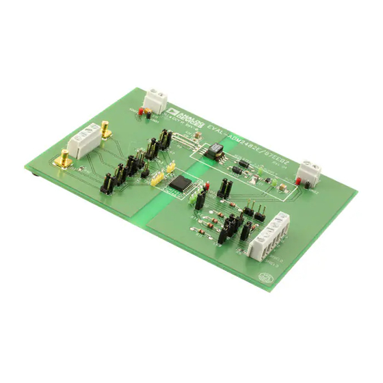
Evaluation Boards for the ADM2482E and ADM2487E Isolated RS-485 Transceivers
FEATURES
Easy evaluation of the
ADM2482E/ADM2487E
Isolated ground plane layout
Configurable as full duplex or half duplex
Evaluation of the
ADM2482E
Evaluation of the
ADM2487E
ADM2482E/ADM2487E
Isolated RS-485/RS-422 interfaces
Process field bus (PROFIBUS) networks
Industrial field networks
Multipoint data transmission systems
EVALUATION KIT CONTENTS
EVAL-ADM2482EEB3Z, EVAL-ADM2487EEB3Z,
EVAL-ADM2482EEB5Z, or EVAL-ADM2487EEB5Z
LOGIC
CONNECTOR
PLEASE SEE THE LAST PAGE FOR AN IMPORTANT
WARNING AND LEGAL TERMS AND CONDITIONS.
at 16 Mbps
at 500 kbps
APPLICATIONS
FUNCTIONAL BLOCK DIAGRAM
CENTER TAPPED
TRANSFORMER
POWER
CONNECTOR
V
DD1
GND
1
V
D1
D2
DD1
OSC
DE
TxD
RxD
RE
GND
1
Evaluation Board User Guide
GENERAL DESCRIPTION
The
ADM2482E/ADM2487E
ADM2482E/ADM2487E
quickly and easily evaluated. The evaluation board allows all of
the input and output functions to be exercised without the need
for external components.
The
ADM2482E/ADM2487E
driver that outputs a pair of square waves to an external trans-
former to provide isolated power. When the ADM2482E/
ADM2487E
are powered by 3.3 V on the logic side (V
former, U3, is required with a turns ratio of 1:1.5 (DA2303-AL).
This ensures that there is enough headroom for the
LDO to output a regulated 3.3 V output (EVAL-ADM2482EEB3Z
and EVAL-ADM2487EEB3Z).
When the
ADM2482E/ADM2487E
logic side, a transformer, U3, is required with a turns ratio of 1:1
(GA3157-AL) to give a 5 V input for the ADP3330, which regu-
lates an output of 3.3 V output (EVAL-ADM2482EEB5Z and
EVAL-ADM2487EEB5Z).
LDO
RECTIFIER
IN
ADP3330
SD
GND
GND
2
ADM2482E/ADM2487E
Figure 1.
Rev. A | Page 1 of 12
evaluation boards allow the
isolated RS-485 transceivers to be
feature an integrated transformer
are powered by 5 V on the
OUT
+3.3V ISO
V
DD2
BUS
CONNECTOR
Y
Z
A
R
T
B
GND
2
GND
2
UG-210
), a trans-
DD1
ADP3330
Advertisement
Table of Contents

Subscribe to Our Youtube Channel
Related Manuals for Analog Devices EVAL-ADM2482EEB3Z


Summary of Contents for Analog Devices EVAL-ADM2482EEB3Z
-
Page 1: Features
U3, is required with a turns ratio of 1:1.5 (DA2303-AL). Multipoint data transmission systems This ensures that there is enough headroom for the ADP3330 EVALUATION KIT CONTENTS LDO to output a regulated 3.3 V output (EVAL-ADM2482EEB3Z and EVAL-ADM2487EEB3Z). EVAL-ADM2482EEB3Z, EVAL-ADM2487EEB3Z, EVAL-ADM2482EEB5Z, or EVAL-ADM2487EEB5Z When the... -
Page 2: Table Of Contents
UG-210 Evaluation Board User Guide TABLE OF CONTENTS Features ....................1 Full Duplex, Bus Biasing And Termination Resistors on Receiver Input................3 ADM2482E/ADM2487E Applications .......... 1 Full Duplex, Bus Biasing And Termination Resistors on Evaluation Kit Contents..............1 ... -
Page 3: Evaluation Board Configurations
3.3 V EVALUATION BOARD Jumpers LK11, LK13, LK7, and LK9 must be inserted for this configuration. The EVAL-ADM2482EEB3Z and EVAL-ADM2487EEB3Z are A termination resistor can also be fitted on the transmitter shipped in a 3.3 V full-duplex configuration without any bus output by inserting RT1. -
Page 4: Changes To Table 1
UG-210 Evaluation Board User Guide Table 1. Board Configurations and Jumper Settings Configuration Jumpers Fitted Jumpers Open Full Duplex Configuration LK 15, LK16 Half-Duplex Configuration (A Connected to Y, B Connected to Z) LK15, LK16 No Biasing Resistors LK7, LK9, LK11, LK13 Bus Biasing Resistors on A/B only LK11, LK13 LK7, LK9... -
Page 5: Change To Figure 2
Evaluation Board User Guide UG-210 EVALUATION BOARD SCHEMATIC AND ARTWORK Figure 2. ADM2482E/ADM2487E Evaluation Board Circuit Diagram Rev. A | Page 5 of 12... -
Page 6: Changes To Figure 3
UG-210 Evaluation Board User Guide Figure 3. ADM2482E/ADM2487E Evaluation Board Silkscreen Rev. A | Page 6 of 12... -
Page 7: Changes To Figure 4
Evaluation Board User Guide UG-210 Figure 4. ADM2482E/ADM2487E Evaluation Board Component Side Rev. A | Page 7 of 12... -
Page 8: Changes To Figure 5
UG-210 Evaluation Board User Guide Figure 5. ADM2482E/ADM2487E Evaluation Board Solder Side Rev. A | Page 8 of 12... -
Page 9: Changes To Table 2 And Related Links Section
X555, GND1, GND2 Test point Vero 20-2137 SKD1, SKD2 ZPD10, DO35_P, Schottky diode Fairchild Semiconductor 1N5817 RS-485 transceiver, 16-lead SOIC_W Analog Devices ADM2482EBRWZ/ADM2487EBRWZ LDO, 6-lead SOT-23 Analog Devices ADP3330 SMT power transformer Coilcraft GA3157-AL/Coilcraft DA2303-AL Only one header is required per board. - Page 10 UG-210 Evaluation Board User Guide NOTES Rev. A | Page 10 of 12...
- Page 11 Evaluation Board User Guide UG-210 NOTES Rev. A | Page 11 of 12...
- Page 12 By using the evaluation board discussed herein (together with any tools, components documentation or support materials, the “Evaluation Board”), you are agreeing to be bound by the terms and conditions set forth below (“Agreement”) unless you have purchased the Evaluation Board, in which case the Analog Devices Standard Terms and Conditions of Sale shall govern. Do not use the Evaluation Board until you have read and agreed to the Agreement.
Need help?
Do you have a question about the EVAL-ADM2482EEB3Z and is the answer not in the manual?
Questions and answers