Table of Contents
Advertisement
Quick Links
One Technology Way • P.O. Box 9106 • Norwood, MA 02062-9106, U.S.A. • Tel: 781.329.4700 • Fax: 781.461.3113 • www.analog.com
Evaluating the
FEATURES
Fully featured evaluation board for the AD7606C-18
On-board power supplies
Standalone capability
SDP-H1
compatible
PC software for control and data analysis
Time and frequency domain
EVALUATION KIT CONTENTS
EVAL-AD7606C18FMCZ evaluation board
ADDITIONAL EQUIPMENT NEEDED
EVAL-SDP-CH1Z
(SDP-H1) high speed controller board
PC running Windows Vista SP2 (32-bit or 64-bit), Windows 7
SP1 (32-bit or 64-bit), Windows 8.1 (32-bit or 64-bit), or
Windows 10 (32-bit or 64-bit) with a USB 2.0 port
DC and ac signal source
SMB and USB cables
External supply (optional)
DOCUMENTS NEEDED
AD7606C-18 data sheet
ONLINE RESOURCES
ACE
software
AD7606C-18 ACE plugin (provided in the ACE software)
AD7606x Family Software Model
PLEASE SEE THE LAST PAGE FOR AN IMPORTANT
WARNING AND LEGAL TERMS AND CONDITIONS.
EVAL-AD7606C18FMCZ
AD7606C-18
8-Channel DAS with 18-Bit, 1 MSPS Bipolar Input,
Simultaneous Sampling ADC
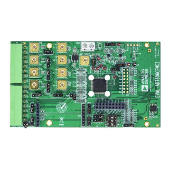
EVALUATION BOARD PHOTOGRAPH
Evaluation Board User Guide
EVALUATION BOARD DESCRIPTION
The EVAL-AD7606C18FMCZ is a fully featured evaluation
board that allows users to evaluate the features of the AD7606C-18
analog-to-digital converter (ADC). The EVAL-AD7606C18FMCZ
is controlled by the EVAL-SDP-CH1Z (SDP-H1) system
demonstration platform (SDP). The SDP-H1 controls the
EVAL-AD7606C18FMCZ through the USB port of a PC using
the Analysis | Control | Evaluation (ACE) software, which is
available to download from the ACE software page or the
AD7606C-18 product page.
The on-board components include the
low noise, low dropout (LDO) linear regulators and an
ADR4525
high precision, band gap voltage reference.
Figure 1 shows the evaluation board photograph. The printed
model number on the evaluation board is EVAL-AD7606CFMCZ.
For full details on the AD7606C-18, see the AD7606C-18 data
sheet, which must be consulted in conjunction with this user
guide when using the EVAL-AD7606C18FMCZ. In addition, full
details on the SDP-H1 are available on the SDP-H1 product page.
Figure 1.
Rev. 0 | Page 1 of 15
UG-1870
ADP7118
5 V and 3.3 V
Advertisement
Table of Contents

Related Manuals for Analog Devices EVAL-AD7606C18FMCZ


Summary of Contents for Analog Devices EVAL-AD7606C18FMCZ
-
Page 1: Features
PC software for control and data analysis demonstration platform (SDP). The SDP-H1 controls the Time and frequency domain EVAL-AD7606C18FMCZ through the USB port of a PC using the Analysis | Control | Evaluation (ACE) software, which is EVALUATION KIT CONTENTS... -
Page 2: Table Of Contents
UG-1870 EVAL-AD7606C18FMCZ Evaluation Board User Guide TABLE OF CONTENTS Features ....................1 Evaluation Board Software ...............6 Evaluation Kit Contents ..............1 Software Installation ..............6 Additional Equipment Needed ............1 Evaluation Board Setup Procedures ...........8 Documents Needed ................1 ACE Software Operation ..............9 Online Resources ................ -
Page 3: Evaluation Board Quick Start Guide
Subminiature Version B (SMB) Ensure that the link options are configured as detailed in connectors, J1 to J8. Table 2. Connect the SDP-H1 to the EVAL-AD7606C18FMCZ. By default, the power for the EVAL-AD7606C18FMCZ is Rev. 0 | Page 3 of 15... -
Page 4: Evaluation Board Hardware
Default Position Function software controls the STBY pin. When using the EVAL-AD7606C18FMCZ in standalone mode without running the ACE software, JP1 allows the selection of standby mode. In this case, change the R8 and R10 resistors to 0 Ω links. - Page 5 Inserting P16 connects the V7− line to ground. Open The ACE software controls the OS0, OS1, and OS2 pins. If using the EVAL-AD7606C18FMCZ in standalone mode, these switches select the logic level on the OS0, OS1, and OS2 pins. Rev. 0 | Page 5 of 15...
-
Page 6: Evaluation Board Software
Warning The ACE software and SDP-H1 drivers must be installed before connecting the EVAL-AD7606C18FMCZ and the SDP-H1 to the USB port of the PC to ensure that the evaluation system is properly recognized when it is connected to the PC. - Page 7 EVAL-AD7606C18FMCZ Evaluation Board User Guide UG-1870 software components to install are preselected (see Figure 5). Click Install. Figure 7. Installation in Progress When the installation is complete, click Next > (see Figure 8), and then click Finish to complete the installation process.
-
Page 8: Evaluation Board Setup Procedures
System Tools, click Device Manager. If the SDP-H1 EVAL-AD7606C18FMCZ. driver is installed and the SDP-H1 is properly connected to Connecting the EVAL-AD7606C18FMCZ and the SDP-H1 the PC, Analog Devices SDP-H1 is shown in the to a PC ADI Development Tools list in the Device Manager After the software is installed, take the following steps to window, as shown in Figure 9. -
Page 9: Ace Software Operation
From the Start menu of the PC, select All Programs > Clicking a dark blue block icon opens a configurable pop-up Analog Devices > ACE> ACE.exe to open the ACE window that allows customization for the data capture, as software main window shown in Figure 10. - Page 10 UG-1870 EVAL-AD7606C18FMCZ Evaluation Board User Guide Figure 11. AD7606C-18 Board View Figure 12. AD7606C-18 Chip View Window Rev. 0 | Page 10 of 15...
-
Page 11: Description Of Memory Map View Window
EVAL-AD7606C18FMCZ Evaluation Board User Guide UG-1870 Figure 13. Configurable Pop-Up Window Figure 14. AD7606C-18 Memory Map View Window DESCRIPTION OF MEMORY MAP VIEW WINDOW only. Click Apply Selected to write the new value on the selected register to the AD7606C-18. -
Page 12: Description Of Analysis Window
UG-1870 EVAL-AD7606C18FMCZ Evaluation Board User Guide Figure 15. AD7606C-18 Analysis View Window DESCRIPTION OF ANALYSIS WINDOW The Oversampling Ratio (Software) pulldown menu in the Device Configuration section can be set between 2 and 64 (in Click Proceed to Analysis in the AD7606C-18 chip view... -
Page 13: Histogram Tab
To perform the automated test for the AD7606C-18, see the The RESULTS pane displays the information related to the dc AD7606C ACE Remote Control page on the Analog Devices, performance. Inc., website and follow the instructions to operate the The Histogram graph displays the number of hits per code within hardware and software, set up the Python/MATLAB the sampled data (see Figure 17). - Page 14 UG-1870 EVAL-AD7606C18FMCZ Evaluation Board User Guide Figure 16. Waveform Tab Figure 17. Histogram Tab Rev. 0 | Page 14 of 15...
- Page 15 By using the evaluation board discussed herein (together with any tools, components documentation or support materials, the “Evaluation Board”), you are agreeing to be bound by the terms and conditions set forth below (“Agreement”) unless you have purchased the Evaluation Board, in which case the Analog Devices Standard Terms and Conditions of Sale shall govern. Do not use the Evaluation Board until you have read and agreed to the Agreement.
Need help?
Do you have a question about the EVAL-AD7606C18FMCZ and is the answer not in the manual?
Questions and answers