Table of Contents
Advertisement
Quick Links
One Technology Way • P.O. Box 9106 • Norwood, MA 02062-9106, U.S.A. • Tel: 781.329.4700 • Fax: 781.461.3113 • www.analog.com
Evaluating the
FEATURES
Supports the detection of UART
UDP transfer capability
ADPD1080/ADPD1081
full configuration
Register level
High level
Graph view
Time graph
Frequency graph
EVALUATION KIT CONTENTS
EVAL-ADPD1081Z-PPG evaluation board
Ribbon cable
ADDITIONAL EQUIPMENT NEEDED
PC running Windows 7 or Windows 10 operating system
EVAL-ADPDUCZ
microcontroller board
ONLINE RESOURCES
ADPD1080/ADPD1081
data sheet
Applications Wavetool software package
PLEASE SEE THE LAST PAGE FOR AN IMPORTANT
WARNING AND LEGAL TERMS AND CONDITIONS.
ADPD1080/ADPD1081
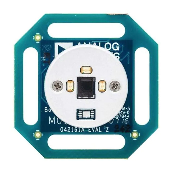
EVAL-ADPD1081Z-PPG EVALUATION BOARD PHOTOGRAPH
EVAL-ADPD1081Z-PPG
Photometric Front Ends
GENERAL DESCRIPTION
The EVAL-ADPD1081Z-PPG evaluation board provides users
with a simple means of evaluating the
photometric front end with an optimized discrete optical design
for vital signs monitoring applications. The evaluation system
includes the Applications Wavetool graphical user interface (GUI)
that provides users with low level and high level configurability,
real-time frequency and time domain analysis, and user datagram
protocol (UDP) transfer capability so the evaluation board can
easily interface to the user development system.
The EVAL-ADPD1081Z-PPG is powered through the ribbon
cable from the
EVAL-ADPDUCZ
(obtained separately). The evaluation board provides three green
light emitting diodes (LEDs) and a 7 mm
design of the evaluation board is optimized for wrist-based
photoplethysmography (PPG) measurements.
For additional information on the functionality of the ADPD1080/
ADPD1081, refer to the
Figure 1.
Rev. 0 | Page 1 of 9
User Guide
UG-1255
ADPD1080/ADPD1081
microcontroller board
2
photodiode (PD). The
ADPD1080/ADPD1081
data sheet.
Advertisement
Table of Contents

Subscribe to Our Youtube Channel
Related Manuals for Analog Devices EVAL-ADPD1081Z-PPG


Summary of Contents for Analog Devices EVAL-ADPD1081Z-PPG
-
Page 1: Features
Frequency graph protocol (UDP) transfer capability so the evaluation board can easily interface to the user development system. EVALUATION KIT CONTENTS The EVAL-ADPD1081Z-PPG is powered through the ribbon EVAL-ADPD1081Z-PPG evaluation board cable from the EVAL-ADPDUCZ microcontroller board Ribbon cable (obtained separately). -
Page 2: Table Of Contents
Optimizing and Running the ADPD1080/ ADPD1081 ...6 Installing the Applications Wavetool ......... 3 Evaluation Board Schematics and Artwork ........7 Connecting the EVAL-ADPDUCZ Microcontroller Board and the EVAL-ADPD1081Z-PPG Evaluation Board ....3 REVISION HISTORY 2/2018—Revision 0: Initial Version Rev. 0 | Page 2 of 9... -
Page 3: Getting Started
Connect the USB cable to the EVAL-ADPDUCZ evaluation board, click ApplicationsWavetool. connect the ribbon cable to the EVAL-ADPD1081Z-PPG board, INSTRUCTIONS TO LOAD THE FIRMWARE and switch the power switch to the ON position (see Figure 3). EVAL-ADPDUCZ microcontroller board may have an older When the USB cable is connected, the second LED below the version of the firmware installed during manufacture. -
Page 4: Usb Uart Connection
UG-1255 EVAL-ADPD1081Z-PPG User Guide If the firmware must be updated, take the following steps: Click the Upgrade button and follow the prompts to upgrade the firmware of the EVAL-ADPDUCZ microcontroller board. Download and install the latest DfuSe USB device firmware upgrade software. -
Page 5: Acquiring Data
ACQUIRING DATA SELECTING THE PROPER VIEW LOAD CONFIGURATION The EVAL-ADPD1081Z-PPG is intended for wrist-based PPG In the upper right corner of the data view window, click the ADPD measurements. Select the ADPD Device data view (see Figure 10). Config button to open the ADPD Config (see Figure 11). Click This view opens a window that allows the user to run the Load DCFG to select a configuration file. -
Page 6: Optimizing And Running The Adpd1080/ Adpd1081
UG-1255 EVAL-ADPD1081Z-PPG User Guide OPTIMIZING AND RUNNING THE ADPD1080/ drive currents, TIA gain, and AFE timing or by using different operating modes that may be more optimal for a specific set of ADPD1081 conditions, for example, using float mode for very low current After the configuration file is loaded, the settings can be further transfer ratio (CTR). -
Page 7: Evaluation Board Schematics And Artwork
EVAL-ADPD1081Z-PPG User Guide UG-1255 EVALUATION BOARD SCHEMATICS AND ARTWORK Figure 13. EVAL-ADPD1081Z-PPG Schematic Rev. 0 | Page 7 of 9... - Page 8 UG-1255 EVAL-ADPD1081Z-PPG User Guide Figure 14. EVAL-ADPD1081Z-PPG Primary Layer Figure 15. EVAL-ADPD1081Z-PPG Secondary Layer Rev. 0 | Page 8 of 9...
- Page 9 By using the evaluation board discussed herein (together with any tools, components documentation or support materials, the “Evaluation Board”), you are agreeing to be bound by the terms and conditions set forth below (“Agreement”) unless you have purchased the Evaluation Board, in which case the Analog Devices Standard Terms and Conditions of Sale shall govern. Do not use the Evaluation Board until you have read and agreed to the Agreement.
Need help?
Do you have a question about the EVAL-ADPD1081Z-PPG and is the answer not in the manual?
Questions and answers