Table of Contents
Advertisement
Quick Links
Advertisement
Table of Contents

Related Manuals for Innosonix MAXX Series


Summary of Contents for Innosonix MAXX Series
- Page 1 MANUAL...
-
Page 2: Table Of Contents
INDEX 1. SAFETY INSTRUCTIONS ............ ... - Page 3 6.1.2. SAVE INTERNAL STORAGE ......... . . ...
- Page 4 6.9. MUTEGROUPS ............ ...
-
Page 5: Safety Instructions
MAXX/HP² Chapter 1. SAFETY INSTRUCTIONS 1.1. GENERAL Chapter 1. SAFETY INSTRUCTIONS 1.1. GENERAL Before using the product, please read this manual and follow all Safety Instructions. They are used to protect you, help to avoid equipment defects and damages resulting from improper use. - Page 6 After switching off the device, wait 30 minutes till touching the device. In the following cases it is necessary to return the amplifier for examination to the manufacturer. Contact details can be found on our website: www.innosonix.de • The unit has been dropped, mechanically damaged or treated improperly. ...
-
Page 7: Ventilation And Cooling
MAXX/HP² Chapter 1. SAFETY INSTRUCTIONS 1.2. VENTILATION AND COOLING 1.2. VENTILATION AND COOLING Built-in and 19-inch racks must be ventilated adequately. The active cooling system inside the device creates front to back ventilation. Figure 1. MAXX/HP² Ventilation 2023-01-05 | Rev. 3.17.0 1.2. -
Page 8: Operating Conditions
MAXX/HP² Chapter 1. SAFETY INSTRUCTIONS 1.3. OPERATING CONDITIONS 1.3. OPERATING CONDITIONS Enviromental 0 - 40°C operating temperature Thermal dissipation Fan, variable speed, temperature controlled front to rear airflow 32 CH @230V @110V amps power off 31 kcal/h 123 BTU/h 31 kcal/h 123 BTU/h idle 84 kcal/h... -
Page 9: Technical Specification
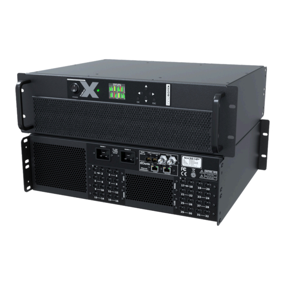
MAXX/HP² Chapter 2. TECHNICAL SPECIFICATION 2.1. MAxx/HP² front view Chapter 2. TECHNICAL SPECIFICATION 2.1. MAxx/HP² front view Figure 2. MA32/HP² front view Table 1. DEVICE ELEMENTS FRONT DESRIPTION NOTE POWER SWITCH Hard disconnect Mains POWER LED POWER LED DISPLAY DISPLAY / BUTTONS BUTTONS DISPLAY / BUTTONS VENTILATION GRILLS... - Page 10 MAXX/HP² Chapter 2. TECHNICAL SPECIFICATION 2.2. MAxx/HP² back view Figure 3. MA32/HP² back view Figure 4. MA24/HP² back view Table 2. DEVICE ELEMENTS BACK DESRIPTION NOTE MAINS SUPPLY MAINS SUPPLY MADI MADI (AES10) / AES3 ETHERNET/DANTE ETHERNET / DANTE AMP OUTPUTS AMP OUTPUT 2023-01-05 | Rev.
-
Page 11: Dimensions & Weight
MAXX/HP² Chapter 2. TECHNICAL SPECIFICATION 2.3. DIMENSIONS & WEIGHT 2.3. DIMENSIONS & WEIGHT Figure 5. MAXX/HP² dimensions Dimensions W 482.60mm (19") H132.55mm (3 RU), D 389.29mm 32CH 24CH Weight 19.6 kg 18.3 kg 2023-01-05 | Rev. 3.17.0 2.3. DIMENSIONS & WEIGHT | 7/86... -
Page 12: Connections & Cable
MAXX/HP² Chapter 2. TECHNICAL SPECIFICATION 2.4. CONNECTIONS & CABLE 2.4. CONNECTIONS & CABLE Control input connectors RJ45 ( 100Mbit/s Ethernet ) Audio signal input connectors RJ45 ( DANTE ), BNC 75R ( MADI Coax, AES3id ), SC Optic ( MADI Fibre ) Speaker connector Wuerth Elektronik 691352710002 Phoenix Contact MSTB 2,5/ 2-ST - 1754449... - Page 13 MAXX/HP² Chapter 2. TECHNICAL SPECIFICATION 2.4. CONNECTIONS & CABLE amps power off idle 1/8 power @ 4 Ohm 1145W 1150W The devices contains an internal fuse see: FUSES The Amplifier comes with a power cord according to the planned place of use. There are two separate power supplies in the amplifier.
-
Page 14: Available Power Cords
MAXX/HP² Chapter 2. TECHNICAL SPECIFICATION 2.4. CONNECTIONS & CABLE 2.4.2. AVAILABLE POWER CORDS DESRIPTION 3-pin Schuko CEE 7/7 3-pin GB BS 1363A IEC-LOCK C19 To release the cable from the amplifier, the red Button has to be pulled to the back. 2023-01-05 | Rev. -
Page 15: Ethernet / Dante
MAXX/HP² Chapter 2. TECHNICAL SPECIFICATION 2.4. CONNECTIONS & CABLE 2.4.3. ETHERNET / DANTE There are two differnet network devices inside the amplifier, the Control Module and Module. There are three different network modes that determine which device can be reached at which network port. ... - Page 16 MAXX/HP² Chapter 2. TECHNICAL SPECIFICATION 2.4. CONNECTIONS & CABLE To change the network modes, use the DEVICE page DANTE SETTINGS. Alternatively, the Dante Contoller Software can be used. (DOWNLOAD HERE) Open the Dante Controller and go to Device View: Figure 7. Dante Controller The Device View Popup appears: Figure 8.
-
Page 17: Dante Ip Settings
MAXX/HP² Chapter 2. TECHNICAL SPECIFICATION 2.4. CONNECTIONS & CABLE seconds till the Dante Device is back online. DANTE IP SETTINGS To control and change IP Settings of DANTE, use the DEVICE page DANTE SETTINGS, or Dante Device View. CONTROL IP SETTINGS There are several ways to change the IP of an Amplifier. -
Page 18: Madi (Aes10) / Aes3
MAXX/HP² Chapter 2. TECHNICAL SPECIFICATION 2.4. CONNECTIONS & CABLE 2.4.4. MADI (AES10) / AES3 MADI (Multichannel Audio Digital Interface) or AES10 is a standard that defines electrical characteristics and the data format of an interface that carries multiple channels of digital audio. There are two Coaxial Inputs available, which also can be used as AES3 Inputs, one optical input and an optical output. -
Page 19: Amp Output
MAXX/HP² Chapter 2. TECHNICAL SPECIFICATION 2.5. AMP OUTPUT 2.5. AMP OUTPUT To connect speakers, use 2-Pol Terminal Blocks. Output Power (EIA J Test 4Ω 8Ω 8Ω Bridge-Mode Standard 1kHz 1% THD) 280W 140W 500W Max output Voltage 52 V 104 V peak peak Max output Current Limited... -
Page 20: Bridge Mode
MAXX/HP² Chapter 2. TECHNICAL SPECIFICATION 2.5. AMP OUTPUT 2.5.1. Bridge Mode In bridge mode, only adjacent channels can be used together, like 1/2, 3/4, 5/6, … 31/32. The + Pin of both channels has to be connected to the speaker, the - stays unused in this mode. -
Page 21: Power Distribution
MAXX/HP² Chapter 2. TECHNICAL SPECIFICATION 2.6. POWER DISTRIBUTION 2.6. POWER DISTRIBUTION • The power supply can deliver 5000W continuous power. To ensure a stable operation in overload situations, the MAXX/HP² involves an overall power limiter. With an attack time of 100ms and a release of 3s the limiter softly reduces the gain of all channels simultaneously not to exceed the maximum available power. -
Page 22: Idfm (Firmware Update And Ip Control)
3.1. DISCOVERY Chapter 3. IDFM (FIRMWARE UPDATE AND IP CONTROL) The IDFM (Innosonix Discovery and Firmware Manager) is available for Windows 10, MAC OSX and Linux. Have a look at our Download Area It is desinged to discover MAXX Devices across subnets and across network modes. It also handles Firmware updates of MAXX Devices. - Page 23 MAXX/HP² Chapter 3. IDFM (FIRMWARE UPDATE AND IP CONTROL) 3.1. DISCOVERY Download / Import Firmware Files FIRMWARE Update Devices UPDATE Device not in same Subnet ⇒ cannot be updated Actual Device Status (Update Status) 2023-01-05 | Rev. 3.17.0 3.1. DISCOVERY | 19/86...
-
Page 24: Ip Settings
MAXX/HP² Chapter 3. IDFM (FIRMWARE UPDATE AND IP CONTROL) 3.2. IP SETTINGS 3.2. IP SETTINGS After clicking on the IP Address in IDFM Discovery view, following popup appears to change IP Settings. IP Settings are described here Control IP Figure 10. IDFM IP Settings 2023-01-05 | Rev. -
Page 25: Firmware Storage
MAXX/HP² Chapter 3. IDFM (FIRMWARE UPDATE AND IP CONTROL) 3.3. FIRMWARE STORAGE 3.3. FIRMWARE STORAGE To update the firmware of a MAXX Device, the correct Firmware must be available in the firmware storage. If there is no Internet connection available, the newest firmware cannot be loaded from our server . -
Page 26: Firmware Update
MAXX/HP² Chapter 3. IDFM (FIRMWARE UPDATE AND IP CONTROL) 3.4. FIRMWARE UPDATE 3.4. FIRMWARE UPDATE After loading a correct firmware file to the FIRMWARE STORAGE, the firmware can be selected in the firmware update popup. If no Firmware is selected, the device will be ignored. -
Page 27: Dsp (Internal)
MAXX/HP² Chapter 4. DSP (internal) Chapter 4. DSP (internal) A DSP is a digital signal processing chain inside the FPGA that calculates the volume control, filtering and limiting parameters on the selected Input Source. There are as many DSP channels as amplifier outputs on the MAXX device. DSPs are "hardwired" to the corresponding amplifier, e.g. -
Page 28: Frontpannel
MAXX/HP² Chapter 5. Frontpannel 5.1. DISPLAY / BUTTONS Chapter 5. Frontpannel 5.1. DISPLAY / BUTTONS 5.1.1. DISPLAY MENU Figure 14. MENU STRUCTURE Table 4. MENU PAGES DESCRIPTION Overview Page with Hostname, IP and Channel Status (see. OVERVIEW) Status Page with Temperatures and PSU Load and Fan Speeds Info Page with Model, Serial, Software Version and Software Options Network Settings Page to change IP type and address 2023-01-05 | Rev. -
Page 29: Overview
MAXX/HP² Chapter 5. Frontpannel 5.1. DISPLAY / BUTTONS 5.1.2. OVERVIEW Figure 15. OVERVIEW EXAMPLES The Overview Page appears at startup, and after a 30 seconds timeout, if another page is selected and no user input occurs. Every channel has its own Levelmeter from -60dBFS to 0dBFS with PEAK as a bar and HOLD as a horizontal line. -
Page 30: Power Led
MAXX/HP² Chapter 5. Frontpannel 5.2. POWER LED 5.2. POWER LED Table 5. POWER LED states COLOR DESRIPTION GREEN everything is ok ORANGE system is booting up one or more channels are in error state BLUE Mains dropout, by pulling the mains cable or press the power switch 2023-01-05 | Rev. -
Page 31: Website
MAXX/HP² Chapter 6. WEBSITE 6.1. HEADER Chapter 6. WEBSITE To open the control page, use a regular web browser like Chrome, Firefox, Safari and enter the IP address or hostname into the address line. Like http://192.168.0.100 or by using the hostname http://AMP1.local The website is the main User Interface to control every setting and get status informations of the amplifier. -
Page 32: Pages
MAXX/HP² Chapter 6. WEBSITE 6.1. HEADER 6.1.1. PAGES Table 6. PAGES IDENTIFIER DESCRIPTION REFERENCE OVERVIEW status and settings of amp channel OVERVIEW INTERFACES device interface status and config INTERFACES DEVICE device specific settings DEVICE MUTEGROUPS mutegroup settings MUTEGROUPS PRESETS device/channel preset edit/save/call/store PRESETS LOGGING syslog with syslog server settings... -
Page 33: Amp Status
MAXX/HP² Chapter 6. WEBSITE 6.1. HEADER 6.1.4. AMP STATUS The Amp Status shows all currently applicable errors. To see the chronological sequence of errors see LOGGING. DESCRIPTION REFERENCE device errors channel errors severity level SEVERITY LEVEL error code ERROR CODES error text 2023-01-05 | Rev. -
Page 34: Footer
MAXX/HP² Chapter 6. WEBSITE 6.2. FOOTER 6.2. FOOTER On the footer, a temperature overview can be seen, which shows the FPGA temperature as well as the maximum temperature on all amp modules. If the AMP temperature exceeds 80°C, a showdown of all amplifier ... -
Page 35: Overview
MAXX/HP² Chapter 6. WEBSITE 6.3. OVERVIEW 6.3. OVERVIEW All channel setting can be done to single and multi-channel (see SELECTION AND GROUPING for multi-channel selection details). DESCRIPTION REFERENCE click to set master volume change master volume by moving the slider click to toggle master mute click opens channel settings modal CHANNEL SETTINGS... - Page 36 MAXX/HP² Chapter 6. WEBSITE 6.3. OVERVIEW If the ANALYZER has detected a valid speaker impedance, the minimum impedance in ohms of the whole spectrum range is indicted in the small speaker icon. Figure 17. Speaker minimum impedance 2023-01-05 | Rev. 3.17.0 6.3.
-
Page 37: Selection And Grouping
MAXX/HP² Chapter 6. WEBSITE 6.4. SELECTION AND GROUPING 6.4. SELECTION AND GROUPING Multiple channels can be selected by clicking on . This feature enables the "multi- channel edit" functionality indicated by the active headline buttons (SETTINGS, POWER, …). The headline buttons open the corresponding modal. The saved selection groups will be used as mute groups MUTEGROUPS ... -
Page 38: Modal Header
MAXX/HP² Chapter 6. WEBSITE 6.5. MODAL HEADER 6.5. MODAL HEADER DESCRIPTION Shows the current selected channels. The "PREV / ALL / NEXT" allows cycling through the selected channels to allow an easy single channel edit. Select a selection group. (see. SELECTION AND GROUPING) Loads the selected group to the selection. -
Page 39: Channel Settings
MAXX/HP² Chapter 6. WEBSITE 6.6. CHANNEL SETTINGS 6.6. CHANNEL SETTINGS 6.6.1. NAME DESCRIPTION Set channel prefix, which will be concatenated with the "INDEX" as final channel name. Set an optional index which is incremented for each selected channel. (only available in multi-edit) Execute changes. -
Page 40: Bridge Mode
MAXX/HP² Chapter 6. WEBSITE 6.6. CHANNEL SETTINGS 6.6.2. BRIDGE MODE DESCRIPTION Indicates summarized state of selected channels. Enable bridge mode for selected channels. Disable bridge mode for selected channels. States for all selected channels. Only adjacent channel pairs can be set to bridge mode, channel 1/2 or 3/4 ... -
Page 41: Dc Coupling
MAXX/HP² Chapter 6. WEBSITE 6.6. CHANNEL SETTINGS 6.6.3. DC COUPLING Figure 19. DC COUPLING Some scientific measurements require the amplifier to output a common DC voltage to bias the speaker coil. By enabling DC COUPLING in internal DC, servo filters are frozen and allow passing DC in the input signal to the amplifier output stage. -
Page 42: Power
MAXX/HP² Chapter 6. WEBSITE 6.6. CHANNEL SETTINGS 6.6.4. POWER Power-off a channel which will stop the class-d amp from switching to save power. Figure 20. POWER 2023-01-05 | Rev. 3.17.0 6.6. CHANNEL SETTINGS | 38/86... -
Page 43: Auto Standby
MAXX/HP² Chapter 6. WEBSITE 6.6. CHANNEL SETTINGS 6.6.5. AUTO STANDBY This feature allows additional power savings by automatically powering down individual channels when no more input signal is present for a configurable amount of time. Power up, after detecting an input level, will require some milliseconds, so ... - Page 44 MAXX/HP² Chapter 6. WEBSITE 6.6. CHANNEL SETTINGS Figure 24. STANDBY on OVERVIEW page 2023-01-05 | Rev. 3.17.0 6.6. CHANNEL SETTINGS | 40/86...
-
Page 45: Input
MAXX/HP² Chapter 6. WEBSITE 6.6. CHANNEL SETTINGS 6.6.6. INPUT Each DSP channel has its own 16x1 input mixer which allows a summation of up to 16 different sources with individual gains. SINGLE CHANNEL DESCRIPTION Select a input interface or test tone (depends on your hard- and software-options). Select channel of interface type. - Page 46 MAXX/HP² Chapter 6. WEBSITE 6.6. CHANNEL SETTINGS MULTI CHANNEL DESCRIPTION Select a input interface or test tone (depends on your hard- and software-options). Select channel of interface type. Gain for the selected source channel. Increments input channel through patch. Appends selected patching to existing patches on the channels. Execute the patch command.
-
Page 47: Mute
MAXX/HP² Chapter 6. WEBSITE 6.6. CHANNEL SETTINGS 6.6.7. MUTE DESCRIPTION Indicates summarized state of selected channels. Unmutes all selected channels. Mutes all selected channels. Shows states of all selected channels. 2023-01-05 | Rev. 3.17.0 6.6. CHANNEL SETTINGS | 43/86... -
Page 48: Channel Volume
MAXX/HP² Chapter 6. WEBSITE 6.6. CHANNEL SETTINGS 6.6.8. CHANNEL VOLUME DESCRIPTION Decreases volume of selected channels by 1 dB. Indicates summarized the state of selected channels. Increases volume of selected channels by 1 dB. Channel volume to set. Apply Settings. Shows vales of selected channels. -
Page 49: Phase
MAXX/HP² Chapter 6. WEBSITE 6.6. CHANNEL SETTINGS 6.6.9. PHASE DESCRIPTION Indicates summarized state of selected channels. Set normal phase. Set reverse phase. Shows vales of selected channels. 2023-01-05 | Rev. 3.17.0 6.6. CHANNEL SETTINGS | 45/86... -
Page 50: Delay
MAXX/HP² Chapter 6. WEBSITE 6.6. CHANNEL SETTINGS 6.6.10. DELAY In the CONFIG column, the current value for all selected channels can be seen. In the upper half of the pop-up, a dedicated value can be set to all selected channels. The delay units is either m (meters), ms (milliseconds) or samples. -
Page 51: Peq
MAXX/HP² Chapter 6. WEBSITE 6.6. CHANNEL SETTINGS 6.6.11. PEQ There are 32 EQ slots that can be set with several EQ types. Some EQ types need more than one EQ slot. 18dB/24dB Low/High passes require two, while 48dB Low/High require four slots. When values are changed but not set to the device, the EQ is in preview mode which is indicated by PREVIEW in the HEADLINE, and the PEQ plot ... -
Page 52: Peq Add / Remove
MAXX/HP² Chapter 6. WEBSITE 6.6. CHANNEL SETTINGS Figure 26. PEQ Fullscreen The Plot shows the overall EQ for this channel, indicated by the white OUTPUT curve. It’s the result of PEQs and ADVANCED EQs. All EQs parameters are shown in the list below the plot, where each parameter can be manually adjusted. - Page 53 MAXX/HP² Chapter 6. WEBSITE 6.6. CHANNEL SETTINGS Figure 27. Drag & Drop Removing a PEQ by dragging its ribbon below the plot on the bin icon or pressing the icon next to the EQ in the overall list below. 2023-01-05 | Rev. 3.17.0 6.6.
- Page 54 MAXX/HP² Chapter 6. WEBSITE 6.6. CHANNEL SETTINGS Figure 28. Remove an EQ 2023-01-05 | Rev. 3.17.0 6.6. CHANNEL SETTINGS | 50/86...
-
Page 55: Advanced Eq (Fir)
MAXX/HP² Chapter 6. WEBSITE 6.6. CHANNEL SETTINGS ADVANCED EQ (FIR) The ADVANCED EQ currently supports loading FIR impulse responses to be convoluted over the output signal. (see: Supported File Formats) Once a file is loaded, it the FIR filter engine can be ENABLED/DISABLED via the toggle button. - Page 56 MAXX/HP² Chapter 6. WEBSITE 6.6. CHANNEL SETTINGS Supported File Formats The Range of each coefficient is limited -4.0 to 3.999 due to the internal fix point representation. The maximum number of Taps is 2048. WAV The WAV File has to be 32Bit Float 48kHz Coefficient File line in file coefficient...
-
Page 57: Copy To / Copy From
MAXX/HP² Chapter 6. WEBSITE 6.6. CHANNEL SETTINGS COPY TO / COPY FROM Both PEQ and ADVANCED can be copied from different channels into the currently selected one, or can be copied to others channels. The Copy to / Copy From pop-up can be opened by pressing the COPY PEQ or COPY ADVANCED. -
Page 58: Limit
MAXX/HP² Chapter 6. WEBSITE 6.6. CHANNEL SETTINGS 6.6.12. LIMIT Each channel offers four limiters, 1x CURRENT, 2x VOLTAGE, 1x POWER. All thresholds are configured in peak values, for simple sine wave signals, the corresponding RMS value can be calculated by peak / sqrt(2). On a single-channel edit, all level meters are shown simultaneously. -
Page 59: Look Ahead Delay
MAXX/HP² Chapter 6. WEBSITE 6.6. CHANNEL SETTINGS subs since, for regular speakers, the actual RMS power is really low with music. Disabled limiters are set to the maximum threshold internally. Due to the internal headroom, it is still possible to see some reduction if the maximum thresholds are reached. -
Page 60: Speaker Settings
MAXX/HP² Chapter 6. WEBSITE 6.6. CHANNEL SETTINGS 6.6.13. SPEAKER SETTINGS SINGLE EDIT Figure 31. SPEAKER SINGLE CHANNEL EDIT VIEW DESCRIPTION Metadata of the active speaker preset. Remove the speaker preset. Download the speaker preset file to share it or apply to others channels. Load a speaker preset file from your computer. - Page 61 MAXX/HP² Chapter 6. WEBSITE 6.6. CHANNEL SETTINGS Figure 32. WEBPAGE SPEAKER PRESET CREATE To create a speaker preset, tune your speaker with the channel DSP settings to your needs. The parameter which can be used inside the speaker preset are: VOLUME, PHASE, DELAY, 32x PEQ, ADVANCED EQ (FIR Filters with 512 Taps), LIMIT.
- Page 62 MAXX/HP² Chapter 6. WEBSITE 6.6. CHANNEL SETTINGS Figure 33. WEBPAGE SPEAKER PRESET LOAD DESCRIPTION Since the channel DSP will be overwritten by the speaker preset values, a backup of the currently loaded settings can be downloaded as channel preset. If a speaker preset is created with a password, the password is required to load the data to the channel 2023-01-05 | Rev.
- Page 63 MAXX/HP² Chapter 6. WEBSITE 6.6. CHANNEL SETTINGS MULTI EDIT Figure 34. SPEAKER MULTI CHANNEL EDIT VIEW DESCRIPTION Mixed speaker preset indicator (different speakers presets are loaded on the selected channel) Delete the currently loaded speaker preset from all selected channels. Load a speaker preset file from your computer to all selected channels.
-
Page 64: Analyzer
MAXX/HP² Chapter 6. WEBSITE 6.6. CHANNEL SETTINGS 6.6.14. ANALYZER The integrated impedance analyzer performs a continuous measurement of the connected speaker impedance over the full frequency spectrum based on the supplied music signal. It’s enabled when the sec_webpage_channel_power of the corresponding channel is active. -
Page 65: Measurement
MAXX/HP² Chapter 6. WEBSITE 6.6. CHANNEL SETTINGS On the DETAIL view, the output of the two complexes FFTs can be seen, which are just for information. The spectrum plots are not intended as a reference for the audio performance of the actual output stage, which is much better than the simple measurements ADCs used to collect the data for the FFTs. - Page 66 MAXX/HP² Chapter 6. WEBSITE 6.6. CHANNEL SETTINGS Figure 37. SWEEP done After the measurement is finished (or any time when the spectrum is completely built up by music), the GREEN impedance curve could be saved as a REFERENCE curve which is persistent during reboots.
- Page 67 MAXX/HP² Chapter 6. WEBSITE 6.6. CHANNEL SETTINGS Figure 38. REFERENCE saved 2023-01-05 | Rev. 3.17.0 6.6. CHANNEL SETTINGS | 63/86...
-
Page 68: Interfaces
MAXX/HP² Chapter 6. WEBSITE 6.7. INTERFACES 6.7. INTERFACES 6.7.1. INTERFACE STATUS Select the interface to derive the audio clock source. In most applications, only one interface like MADI or DANTE is used to supply audio data AND the audio clock. In the SYNC SELECT column, the preferred interface is selected. -
Page 69: Input
MAXX/HP² Chapter 6. WEBSITE 6.7. INTERFACES 6.7.2. INPUT The INPUT pop-up allows the labelling of all channels of each input interface and shows individual stream status. The most interesting part is the DANTE tab, which allows assigning streams to the Dante module. -
Page 70: Madi Fibre/Dante Output
MAXX/HP² Chapter 6. WEBSITE 6.7. INTERFACES 6.7.3. MADI FIBRE/DANTE OUTPUT Figure 40. WEBPAGE INTERFACES OUTPUT DESCRIPTION Select Output to Config Select the source of the MADI FIBRE TX jack. This can either be "INTERNAL TX" which uses the internal MADI transmitter, or any of the other MADI RX jacks. -
Page 71: Device
MAXX/HP² Chapter 6. WEBSITE 6.8. DEVICE 6.8. DEVICE The DEVICE page offers different global settings that affect the amplifier device. 6.8.1. SETTINGS The HOSTNAME is used in DNS for IP resolving. LOCATION is just a string to add some additional information to the device, like where is it located. When IDENTIFY is active, the device will visually identify itself by blinking leds. -
Page 72: Time
MAXX/HP² Chapter 6. WEBSITE 6.8. DEVICE It’s pretty handy to use the SYNC WITH HOSTNAME option, which will use the amplifier’s HOSTNAME and append -DANTE to it, which is used as Dante IDENTITY. 6.8.3. TIME Set system time and time zone. If the device is connected to the internet, it will try to synchronize its RTC (real time clock) to an NTP time-server. -
Page 73: Housing
MAXX/HP² Chapter 6. WEBSITE 6.8. DEVICE 6.8.5. HOUSING FAN MODE NORMAL is the recommended mode to keep all components as cool as possible to improve lifetime. When not much output power is required, the FAN MODE could be changed to SILENT or PASSIVE (LP² only) which will use different fan speeds to reduce noise. -
Page 74: Remote Mute
6.8.8. REMOTE MUTE Enable remote mute, this will provide a GPI interface to mute the entire device, also known as dead man switch. Which require an external Innosonix Remote Mute Server, multiple devices can share one server. 6.8.9. DEVICE REBOOT Simply performs a complete reboot of the device. -
Page 75: Mutegroups
MAXX/HP² Chapter 6. WEBSITE 6.9. MUTEGROUPS 6.9. MUTEGROUPS Mute groups assignment are derived from selection groups (SELECTION AND GROUPING). DESCRIPTION Only enabled mute groups are taken into account when the final mute result is calculated. Mute / unmute mute group. If solo auto clear is activated, only one solo can be active. -
Page 76: Presets
MAXX/HP² Chapter 6. WEBSITE 6.10. PRESETS 6.10. PRESETS DESCRIPTION Load all device settings to the preset editor ( ). Device presets do include fixed mapping of parameters to specific channels. Load setting from one specific channel to preset editor ( Upload a file from your computer to the editor ( ) . -
Page 77: Logging
MAXX/HP² Chapter 6. WEBSITE 6.11. LOGGING 6.11. LOGGING DESCRIPTION select syslog lines to load refresh syslog table export complete syslog from device delete syslog files on the device chronological errors config connection to external syslog server 2023-01-05 | Rev. 3.17.0 6.11. -
Page 78: Metering
MAXX/HP² Chapter 6. WEBSITE 6.12. METERING 6.12. METERING DESCRIPTION input level after input mixer measured current, voltage and power with limiter reductions output level with hardware reduction (sum of PSU Limit and Thermo Limit) 2023-01-05 | Rev. 3.17.0 6.12. METERING | 74/86... -
Page 79: Error Codes
MAXX/HP² Chapter 7. ERROR CODES Chapter 7. ERROR CODES Table 9. SEVERITY LEVEL TYPE DESCRIPTION EMERGENCY system is unusable ALERT action must be taken immediately CRITICAL critical conditions ERROR error conditions WARNING warning conditions NOTICE normal but significant condition INFO informational Table 10. - Page 80 MAXX/HP² Chapter 7. ERROR CODES SEVERITY DESCRIPTION ALERT FAN controller no longer available, please try to restart the device Overtemp emergency shutdown init, all Fans will turn up, till temperature out of CRITICAL critical range ALERT PSU monitoring no longer available, please try to restart the device ERROR No settings file available ⇒...
-
Page 81: Restful Api
MAXX/HP² Chapter 8. RESTful API Chapter 8. RESTful API There is a RESTful API with JSON data implemented on the device. Every Parameter can be set, and every status can be read over this Interface. All available commands are documented at REST API DOC on the webpage. -
Page 82: Get Device Infomrations
MAXX/HP² Chapter 8. RESTful API 8.1. GET DEVICE INFOMRATIONS 8.1. GET DEVICE INFOMRATIONS COMMAND info/device TYPE CURL-COMMAND curl ${HOST_IP}/rest-api/info/device RESPONSE "model_name": "MA32LP2", "channel": 32, "options": ["D1","D2","IF1","M1","IF3"], "psu_fan": true, "housing_fan": true, "sd_card": true, "rtc": true, ... -
Page 83: Get Channel Volume Options
MAXX/HP² Chapter 8. RESTful API 8.3. GET CHANNEL VOLUME OPTIONS 8.3. GET CHANNEL VOLUME OPTIONS COMMAND settings/channel/{channel_id}/dsp/volume TYPE OPTIONS CURL-COMMAND curl -X OPTIONS ${HOST_IP}/rest-api/settings/channel/1/dsp/volume RESPONSE {"value": [-72.0, 24.0, 0.1 , "dB"]} {"value": [MIN , MAX , STEP, UNIT]} 8.4. REMOVE PRESET WITH NAME TEST COMMAND preset/storage/{preset_name} TYPE... -
Page 84: Service
MAXX/HP² Chapter 9. SERVICE 9.1. FUSES Chapter 9. SERVICE CAUTION - THESE SERVICING INSTRUCTIONS ARE FOR USE BY QUALIFIED SERVICE PERSONNEL ONLY. TO REDUCE THE RISK OF ELECTRIC SHOCK DO NOT PERFORM ANY SERVICING OTHER THAN THAT CONTAINED IN THE OPERATING INSTRUCTIONS UNLESS YOU ARE QUALIFIED TO DO SO. -
Page 85: Spare Parts
Clean the filter with compressed air and put it back together. 9.4. SPARE PARTS Table 12. SPARE PARTS INNOSONIX PART DESRIPTION REFERENCE NUMBER 12578 2-Pol Speaker Connector CONNECTIONS &... - Page 86 MAXX/HP² Chapter 9. SERVICE 9.4. SPARE PARTS INNOSONIX PART DESRIPTION REFERENCE NUMBER 13358 power cord C19 Typ G 2m (IEC-LOCK C13 to 3-pin GB BS 1363A) AVAILABLE POWER CORDS 2023-01-05 | Rev. 3.17.0 9.4. SPARE PARTS | 82/86...
-
Page 87: Disposing
MAXX/HP² Chapter 10. DISPOSING Chapter 10. DISPOSING Electrical and electronic equipment must be disposed of separately from normal waste at the end of its operational lifetime. Please dispose of this product according to the respective national regulations or contractual agreements. If there are any further questions concerning the disposal of this product, please contact the manufacturer. -
Page 88: Eu Declaration Of Conformity
Chapter 11. EU Declaration of Conformity 11.1. EN 55032:2012 Chapter 11. EU Declaration of Conformity The company Innosonix GmbH declares under sole responsibility that the products MA24/HP² and MA32/HP² complies with the following directives and standards • EMC Directive 2014/30/EU • Low Voltage Directive 2014/35/EU •... -
Page 89: 62368-1:2014/Ac:2015
Chapter 11. EU Declaration of Conformity 11.3. EN 62368-1:2014/AC:2015 11.3. EN 62368-1:2014/AC:2015 Audio/video, information and communication technology equipment Part 1: Safety requirements 11.4. MANUFACTURER Innosonix GmbH Hauptstraße 35 D - 96482 Ahorn 2023-01-05 | Rev. 3.17.0 11.3. EN 62368-1:2014/AC:2015 | 85/86... -
Page 90: Fcc Declaration Of Conformity
MAXX/HP² Chapter 12. FCC Declaration of Conformity Chapter 12. FCC Declaration of Conformity This equipment has been tested and found to comply with the limits for a Class A digital device, pursuant to Part 15 of the FCC Rules. These limits are designed to provide reasonable protection against harmful interference when the equipment is operated in a commercial environment.
Need help?
Do you have a question about the MAXX Series and is the answer not in the manual?
Questions and answers