Table of Contents
Advertisement
Quick Links
Advertisement
Table of Contents

Related Manuals for Innosonix MAXX Series


Summary of Contents for Innosonix MAXX Series
-
Page 2: Table Of Contents
INDEX 1. SAFETY INSTRUCTIONS ............ ... - Page 3 METERING ............ ...
-
Page 4: Safety Instructions
MA32/D Chapter 1. SAFETY INSTRUCTIONS Chapter 1. SAFETY INSTRUCTIONS Before using the product, please read this manual and follow all Safety Instructions. They are used to protect you, help to avoid equipment defects and damages resulting from improper use. Keep this manual in a safe place. CAUTION: THE POWER SUPPLY CORD IS USED AS THE MAIN DISCONNECT DEVICE, ENSURE THAT THE SOCKET-OUTLET IS LOCATED/INSTALLED NEAR THE EQUIPMENT AND IS EASILY ACCESSIBLE... - Page 5 After switching off the device, wait 30 minutes till touching the device. In the following cases it is necessary to return the amplifier for examination to the manufacturer. Contact details can be found on our website: www.innosonix.de • The unit has been dropped, mechanically damaged or treated improperly. ...
-
Page 6: Installation Instructions
MA32/D Chapter 1. SAFETY INSTRUCTIONS 1.1. INSTALLATION INSTRUCTIONS 1.1. INSTALLATION INSTRUCTIONS All devices can be installed in a 19-inch rack. Screw the devices at each of the two Mounting holes of the mounting bracket on the front. Use Screws with a sufficiently large head diameter and lock washers. -
Page 7: Hardware
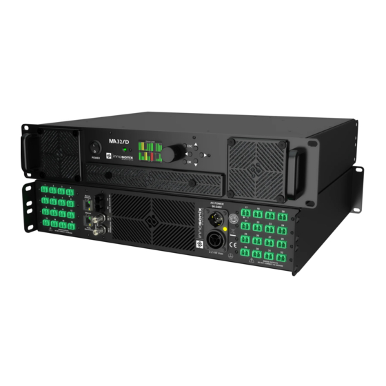
MA32/D Chapter 2. HARDWARE 2.1. CONTROLS Chapter 2. HARDWARE 2.1. CONTROLS 100 - 240V, ~50/60Hz Element Nr. Function Power switch disconnects the unit from the mains Ventilation grille. Please clean to ensure an unhindered airflow through the device Power LED. Red, Yellow or Green TFT Display Encoder knob for adjusting values Keys to enter values and menu navigation... -
Page 8: Ethernet
MA32/D Chapter 2. HARDWARE 2.2. ETHERNET Element Nr. Function MADI (AES10) BNC Secondary. Connection for 75Ohm coaxial cable, e.g. RG59 MADI (AES10) BNC Primary. Connection for 75Ohm coaxial cable, e.g. RG59 Ventilation grills (front to back ventilation) Mains Connection. Neutrik Powercon True 1 with Loop- through facility. -
Page 9: Gain
MA32/D Chapter 2. HARDWARE 2.4. GAIN • Power 16 Ohm → 68W RMS (1% THD+N), 140W Peak 8 Ohm → 130W RMS (1% THD+N), 280W Peak 4 Ohm → 270W RMS (1% THD+N), 530W Peak POWER DISTRIBUTION • The power supply can deliver 2000W continuous power. To ensure a stable operation in overload situations, the MA32 involves an overall power limiter. -
Page 10: Amp Chip / Channel Mapping
MA32/D Chapter 2. HARDWARE 2.5. PROTECTION CIRCUITS Protection Function Description Temperature An assembly consisting of 8 channels shuts down at 85°C heat sink temperature. The remaining 24 stay active. With a Hysteresis of 25 ° C, i.e., at 60 ° C, the affected group turns on again. -
Page 11: Speaker Connection
MA32/D Chapter 2. HARDWARE 2.6. SPEAKER CONNECTION 2.6. SPEAKER CONNECTION The speaker terminal is a connector from Wuerth Elektronik. It is a 2-pin connector with 5mm grid and item number 691352710002. Phoenix contact MSTB 2,5/ 2-ST - 1754449 can be used, too. In procurement problems, please feel free to contact us. We recommend a cable with a cross-section of at least 1.0 mm²... -
Page 12: Heat Generation And Dissipation
MA32/D Chapter 3. HEAT GENERATION AND DISSIPATION Chapter 3. HEAT GENERATION AND DISSIPATION The idle power dissipation of the amplifier is approx 165W. The maximum arise of heat is about 640 W. This has to be considered in the planning of ventilation and air conditioning as "worst case". -
Page 13: Software
4.1. IDFM (FIRMWARE UPDATE AND IP CONTROL) Chapter 4. SOFTWARE 4.1. IDFM (FIRMWARE UPDATE AND IP CONTROL) The IDFM (Innosonix Discovery and Firmware Manager) is available for Windows 10, MAC OSX and Linux. Have a look at our Download Area It is desinged to discover MAXX Devices across subnets and across network modes (See ETHERNET). -
Page 14: Discovery
MA32/D Chapter 4. SOFTWARE 4.1. IDFM (FIRMWARE UPDATE AND IP CONTROL) 4.1.1. DISCOVERY The Discovery process starts after opening the IDFM Tool. All available Devices will appear in the list view. Be sure the firewall allows TCP and UDP connections. Figure 1. -
Page 15: Ip Settings
MA32/D Chapter 4. SOFTWARE 4.1. IDFM (FIRMWARE UPDATE AND IP CONTROL) 4.1.2. IP SETTINGS After clicking on the IP Address in IDFM Discovery view, following popup appears to change IP Settings. IP Settings are described here Control IP Figure 2. IDFM IP Settings 2021-10-20 | Rev. -
Page 16: Firmware Storage
MA32/D Chapter 4. SOFTWARE 4.1. IDFM (FIRMWARE UPDATE AND IP CONTROL) 4.1.3. FIRMWARE STORAGE To update the firmware of a MAXX Device, the correct Firmware must be available in the firmware storage. If there is no Internet connection available, the newest firmware cannot be loaded from our server . -
Page 17: Firmware Update
MA32/D Chapter 4. SOFTWARE 4.1. IDFM (FIRMWARE UPDATE AND IP CONTROL) 4.1.4. FIRMWARE UPDATE After loading a correct firmware file to the FIRMWARE STORAGE, the firmware can be selected in the firmware update popup. If no Firmware is selected, the device will be ignored. -
Page 18: Dsp (Internal)
MA32/D Chapter 4. SOFTWARE 4.2. DSP (internal) 4.2. DSP (internal) The internal signal path of a MAXX Device depends on the following software and hardware options: • Opt. M1 Speaker Monitoring Monitoring of the connected speakers using 20kHz pilot tone to detect defective speakers or failure in the supply cable to the speaker. -
Page 19: User Interfaces
MA32/D Chapter 4. SOFTWARE 4.3. USER INTERFACES Figure 5. DSP Block Image DSP Features Architecture FPGA based 32-bit fixed point Inputs 16 x input matrix sine, white- pink- brown-noise Mute, Volume, Phase Filter per channel 32 x EQ / Highpass / Lowpass Filter types bell, notch, highshelf, lowshelf High- Lowpass types... -
Page 20: Display Menu
MA32/D Chapter 4. SOFTWARE 4.3. USER INTERFACES DISPLAY MENU Figure 6. MENU STRUCTURE Table 2. MENU PAGES DESCRIPTION Overview Page with Hostname, IP and Channel Status (see. OVERVIEW) Status Page with Temperatures and PSU Load and Fan Speeds Info Page with Model, Serial, Software Version and Software Options Network Settings Page to change IP type and address 2021-10-20 | Rev. -
Page 21: Overview
MA32/D Chapter 4. SOFTWARE 4.3. USER INTERFACES OVERVIEW Figure 7. OVERVIEW EXAMPLES The Overview Page appears at startup, and after a 30 seconds timeout, if another page is selected and no user input occurs. Every channel has its own Levelmeter from -60dBFS to 0dBFS with PEAK as a bar and HOLD as a horizontal line. -
Page 22: Power Led
MA32/D Chapter 4. SOFTWARE 4.3. USER INTERFACES 4.3.2. POWER LED FRONT VIEW Table 3. POWER LED states COLOR DESRIPTION GREEN everything is ok ORANGE system is booting up one or more channels are in error state 2021-10-20 | Rev. 3.7.5 4.3. -
Page 23: Website
MA32/D Chapter 4. SOFTWARE 4.3. USER INTERFACES 4.3.3. WEBSITE To get to the website, open the IP or open the mDNS name. The website is the main User Interface to control every setting and get status informations of the amplifier. ... -
Page 24: Pages
MA32/D Chapter 4. SOFTWARE 4.3. USER INTERFACES PAGES WEBPAGE HEADER Table 4. PAGES IDENTIFIER DESCRIPTION REFERENCE OVERVIEW status and settings of amp channel OVERVIEW INTERFACES device interface status and config INTERFACES DEVICE device specific settings DEVICE MUTEGROUPS mutegroup settings MUTEGROUPS PRESETS device/channel preset edit/save/call/store PRESETS... -
Page 25: Amp Status
MA32/D Chapter 4. SOFTWARE 4.3. USER INTERFACES AMP STATUS The Amp Status shows all currently applicable errors. To see the chronological sequence of errors see LOGGING. DESCRIPTION REFERENCE device errors channel errors severity level SEVERITY LEVEL error code ERROR CODES error text 2021-10-20 | Rev. -
Page 26: Footer
MA32/D Chapter 4. SOFTWARE 4.3. USER INTERFACES FOOTER DESCRIPTION REFERENCE Amp and FPGA temperatures (at 80°C the Amplifier executes emergency shutdown) device serial number software version navigate to license page navigate to rest api doc RESTful API navigate to legacy api doc 2021-10-20 | Rev. -
Page 27: Overview
MA32/D Chapter 4. SOFTWARE 4.3. USER INTERFACES OVERVIEW All channel setting can be done to single and multi-channel (see SELECTION AND GROUPING for multi-channel selection details). DESCRIPTION REFERENCE click to set master volume change master volume by moving the slider click to toggle master mute click opens channel settings modal CHANNEL SETTINGS... - Page 28 MA32/D Chapter 4. SOFTWARE 4.3. USER INTERFACES SELECTION AND GROUPING Multiple channels can be selected by clicking on . This feature enables the "multi- channel edit" functionality indicated by the active headline buttons (SETTINGS, POWER, …). The headline buttons open the corresponding modal. The saved selection groups will be used as mute groups MUTEGROUPS ...
- Page 29 MA32/D Chapter 4. SOFTWARE 4.3. USER INTERFACES MODAL HEADER DESCRIPTION Shows the current selected channels. The "PREV / ALL / NEXT" allows cycling through the selected channels to allow an easy single channel edit. Select a selection group. (see. SELECTION AND GROUPING) Loads the selected group to the selection.
- Page 30 MA32/D Chapter 4. SOFTWARE 4.3. USER INTERFACES CHANNEL SETTINGS CHANNEL NAME DESCRIPTION Set channel prefix, which will be concatenated with the "INDEX" as final channel name. Set an optional index which is incremented for each selected channel. (only available in multi-edit) Execute changes.
- Page 31 MA32/D Chapter 4. SOFTWARE 4.3. USER INTERFACES BRIDGE MODE DESCRIPTION Indicates summarized state of selected channels. Enable bridge mode for selected channels. Disable bridge mode for selected channels. States for all selected channels. Only adjacent channel pairs can be set to bridge mode, channel 1/2 or 3/4 ...
- Page 32 MA32/D Chapter 4. SOFTWARE 4.3. USER INTERFACES CHANNEL POWER Power-off a channel will stop the class-d amp from switching to save idle power. DESCRIPTION Indicates summarized state of selected channel. Activate all selected channels. Deactivate all selected channels. States for all selected channels. 2021-10-20 | Rev.
- Page 33 MA32/D Chapter 4. SOFTWARE 4.3. USER INTERFACES CHANNEL INPUT Each DSP channel has its own 16x1 input mixer which allows a summation of up to 16 different sources with individual gains. SINGLE CHANNEL DESCRIPTION Select a input interface or test tone (depends on your hard- and software-options). Select channel of interface type.
- Page 34 MA32/D Chapter 4. SOFTWARE 4.3. USER INTERFACES MULTI CHANNEL DESCRIPTION Select a input interface or test tone (depends on your hard- and software-options). Select channel of interface type. Gain for the selected source channel. Increments input channel through patch. Appends selected patching to existing patches on the channels. Execute the patch command.
- Page 35 MA32/D Chapter 4. SOFTWARE 4.3. USER INTERFACES CHANNEL MUTE DESCRIPTION Indicates summarized state of selected channels. Unmutes all selected channels. Mutes all selected channels. Shows states of all selected channels. 2021-10-20 | Rev. 3.7.5 4.3. USER INTERFACES | 32/60...
- Page 36 MA32/D Chapter 4. SOFTWARE 4.3. USER INTERFACES CHANNEL VOLUME DESCRIPTION Decreases volume of selected channels by 1 dB. Indicates summarized the state of selected channels. Increases volume of selected channels by 1 dB. Channel volume to set. Apply Settings. Shows vales of selected channels. 2021-10-20 | Rev.
- Page 37 MA32/D Chapter 4. SOFTWARE 4.3. USER INTERFACES CHANNEL PHASE DESCRIPTION Indicates summarized state of selected channels. Set normal phase. Set reverse phase. Shows vales of selected channels. 2021-10-20 | Rev. 3.7.5 4.3. USER INTERFACES | 34/60...
- Page 38 MA32/D Chapter 4. SOFTWARE 4.3. USER INTERFACES CHANNEL DELAY DESCRIPTION Indicates summarized delay of selected channels. When setting the delay in meters, an air temperature has to be specified to calculate the speed of sound. Delay can be set in different units, like samples, meters, milliseconds. Shows vales of selected channels.
- Page 39 MA32/D Chapter 4. SOFTWARE 4.3. USER INTERFACES CHANNEL EQ There are 32 EQ slots that can be set with several EQ types. Some EQ types need more than one EQ slot. 18dB/24dB Low/High passes require two, while 48dB Low/High require four slots. When values are changed but not set to the device, the EQ is in preview ...
- Page 40 MA32/D Chapter 4. SOFTWARE 4.3. USER INTERFACES DESCRIPTION Enables fullscreen mode. Toggle visibility of peq sum plot. Toggle visibility of advanced eq plot. Indicates preview mode. Drag the grab point with the mouse to change frequency/gain, use the mouse wheel to change the quality. Switch between the PEQ / ADVANCED EQ settings.
- Page 41 MA32/D Chapter 4. SOFTWARE 4.3. USER INTERFACES ADVANCED EQ (FIR) DESCRIPTION Enable/disable the FIR filter on the selected channel. Name of the loaded FIR filter. Taps of the loaded FIR filter. Internal calculated CRC over the fixed point coefficients to indicate even single bit differences in the loaded filters.
- Page 42 MA32/D Chapter 4. SOFTWARE 4.3. USER INTERFACES CHANNEL LIMIT DESCRIPTION Shows reduction and measured input level (Vp, Ap, or W) of each limiter. Set threshold attack and release of individual limiter. Reduction level disabled in multi-edit, each limiter can be selected and is highlighted by the blue line. Shows limiter values of the selected limiter and selected channels.
- Page 43 MA32/D Chapter 4. SOFTWARE 4.3. USER INTERFACES CHANNEL SPEAKER SETTINGS SINGLE EDIT Figure 10. SPEAKER SINGLE CHANNEL EDIT VIEW DESCRIPTION Metadata of the active speaker preset. Remove the speaker preset. Download the speaker preset file to share it or apply to others channels. Load a speaker preset file from your computer.
- Page 44 MA32/D Chapter 4. SOFTWARE 4.3. USER INTERFACES Figure 11. WEBPAGE SPEAKER PRESET CREATE To create a speaker preset, tune your speaker with the channel DSP settings to your needs. The parameter which can be used inside the speaker preset are: VOLUME, PHASE, DELAY, 32x PEQ, ADVANCED EQ (FIR Filters with 512 Taps), LIMIT.
- Page 45 MA32/D Chapter 4. SOFTWARE 4.3. USER INTERFACES Figure 12. WEBPAGE SPEAKER PRESET LOAD DESCRIPTION Since the channel DSP will be overwritten by the speaker preset values, a backup of the currently loaded settings can be downloaded as channel preset. If a speaker preset is created with a password, the password is required to load the data to the channel 2021-10-20 | Rev.
- Page 46 MA32/D Chapter 4. SOFTWARE 4.3. USER INTERFACES MULTI EDIT Figure 13. SPEAKER MULTI CHANNEL EDIT VIEW DESCRIPTION Mixed speaker preset indicator (different speakers presets are loaded on the selected channel) Delete the currently loaded speaker preset from all selected channels. Load a speaker preset file from your computer to all selected channels.
-
Page 47: Interfaces
MA32/D Chapter 4. SOFTWARE 4.3. USER INTERFACES INTERFACES Figure 14. WEBPAGE INTERFACES DESCRIPTION Select an interface to synchronize the internal audio word clock generation. Interface name. Interface status see. SYNC STATUS Sampling rate. Available channel on this interface. Select the source of the MADI FIBRE TX jack. This can either be "INTERNAL TX" which uses the internal MADI transmitter, or any of the other MADI RX jacks. - Page 48 MA32/D Chapter 4. SOFTWARE 4.3. USER INTERFACES OUTPUT PRESETS Channel assignments on MADI TX and Dante TX are the same. available Output presets MADI FIBRE (Ch. 1 - 64) MADI FIBRE (Ch. 33 - 64) MADI COAX 1 (Ch. 1 - 64) MADI COAX 1 (Ch.
-
Page 49: Device
Master Volume ramp-up-time in seconds, if enabled. Enable remote mute, this will provide a GPI interface to mute the entire device, also known as dead man switch. Which require an external Innosonix Remote Mute Server, multiple devices can share one server. 2021-10-20 | Rev. 3.7.5... - Page 50 MA32/D Chapter 4. SOFTWARE 4.3. USER INTERFACES The "HOSTNAME" is used in DNS for IP resolving. "LOCATION" is just a string to add some additional information to the device, like where is it located. Set IP setting, this will disconnect the web page. Manually connect to the new IP or HOSTNAME in your browser. "VOLTAGE REFERENCE"...
-
Page 51: Mutegroups
MA32/D Chapter 4. SOFTWARE 4.3. USER INTERFACES MUTEGROUPS Mute groups assignment are derived from selection groups (SELECTION AND GROUPING). DESCRIPTION Only enabled mute groups are taken into account when the final mute result is calculated. Mute / unmute mute group. If solo auto clear is activated, only one solo can be active. -
Page 52: Presets
MA32/D Chapter 4. SOFTWARE 4.3. USER INTERFACES PRESETS DESCRIPTION Load all device settings to the preset editor ( ). Device presets do include fixed mapping of parameters to specific channels. Load setting from one specific channel to preset editor ( Upload a file from your computer to the editor ( ) . -
Page 53: Logging
MA32/D Chapter 4. SOFTWARE 4.3. USER INTERFACES LOGGING DESCRIPTION select syslog lines to load refresh syslog table export complete syslog from device delete syslog files on the device chronological errors config connection to external syslog server 2021-10-20 | Rev. 3.7.5 4.3. -
Page 54: Metering
MA32/D Chapter 4. SOFTWARE 4.3. USER INTERFACES METERING DESCRIPTION input level after input mixer measured current, voltage and power with limiter reductions output level with hardware reduction (sum of PSU Limit and Thermo Limit) 2021-10-20 | Rev. 3.7.5 4.3. USER INTERFACES | 51/60... -
Page 55: Error Codes
MA32/D Chapter 4. SOFTWARE 4.3. USER INTERFACES 4.3.4. ERROR CODES Table 5. SEVERITY LEVEL TYPE DESCRIPTION EMERGENCY system is unusable ALERT action must be taken immediately CRITICAL critical conditions ERROR error conditions WARNING warning conditions NOTICE normal but significant condition INFO informational Table 6. - Page 56 MA32/D Chapter 4. SOFTWARE 4.3. USER INTERFACES SEVERITY DESCRIPTION ALERT FAN controller no longer available, please try to restart the device Overtemp emergency shutdown init, all Fans will turn up, till temperature out of CRITICAL critical range ALERT PSU monitoring no longer available, please try to restart the device ERROR No settings file available ⇒...
-
Page 57: Restful Api
MA32/D Chapter 4. SOFTWARE 4.3. USER INTERFACES 4.3.5. RESTful API There is a RESTful API with JSON data implemented on the device. Every Parameter can be set, and every status can be read over this Interface. All available commands are documented at REST API DOC on the webpage. -
Page 58: Get Device Infomrations
MA32/D Chapter 4. SOFTWARE 4.3. USER INTERFACES GET DEVICE INFOMRATIONS COMMAND info/device TYPE CURL-COMMAND curl ${HOST_IP}/rest-api/info/device RESPONSE "model_name": "MA32LP2", "channel": 32, "options": ["D1","D2","IF1","M1","IF3"], "psu_fan": true, "housing_fan": true, "sd_card": true, "rtc": true, "sw_revision": "3.3.0", ... -
Page 59: Get Channel Volume Options
MA32/D Chapter 4. SOFTWARE 4.3. USER INTERFACES GET CHANNEL VOLUME OPTIONS COMMAND settings/channel/{channel_id}/dsp/volume TYPE OPTIONS CURL-COMMAND curl -X OPTIONS ${HOST_IP}/rest-api/settings/channel/1/dsp/volume RESPONSE {"value": [-72.0, 24.0, 0.1 , "dB"]} {"value": [MIN , MAX , STEP, UNIT]} REMOVE PRESET WITH NAME TEST COMMAND preset/storage/{preset_name} TYPE DELETE... -
Page 60: Dimensions And Weight
MA32/D Chapter 5. DIMENSIONS AND WEIGHT 5.1. DIMENSIONS Chapter 5. DIMENSIONS AND WEIGHT 5.1. DIMENSIONS 465,00 482,60 5.2. WEIGHT 15.0 kg Electrical and electronic equipment must be disposed of separately from normal waste at the end of its operational lifetime. Please dispose of this product according to the respective national regulations or contractual agreements. - Page 61 MA32/D Chapter 5. DIMENSIONS AND WEIGHT 5.2. WEIGHT 2021-10-20 | Rev. 3.7.5 5.2. WEIGHT | 58/60...
-
Page 62: Eu Declaration Of Conformity
Chapter 6. EU DECLARATION OF CONFORMITY 6.1. EN 55032:2012 Chapter 6. EU DECLARATION OF CONFORMITY The company Innosonix GmbH declares under sole responsibility that the product MA32/D complies with the following directives and standards • EMC Directive 2014/30/EU • Low Voltage Directive 2014/35/EU •... -
Page 63: 62368-1:2014/Ac:2015
Chapter 6. EU DECLARATION OF CONFORMITY 6.3. EN 62368-1:2014/AC:2015 6.3. EN 62368-1:2014/AC:2015 Audio/video, information and communication technology equipment Part 1: Safety requirements 6.4. MANUFACTURER Innosonix GmbH Hauptstraße 35 D - 96482 Ahorn 2021-10-20 | Rev. 3.7.5 6.3. EN 62368-1:2014/AC:2015 | 60/60...
Need help?
Do you have a question about the MAXX Series and is the answer not in the manual?
Questions and answers