Sign In
Upload
Download
Table of Contents
Contents
Add to my manuals
Delete from my manuals
Share
URL of this page:
HTML Link:
Bookmark this page
Add
Manual will be automatically added to "My Manuals"
Print this page
×
Bookmark added
×
Added to my manuals
Manuals
Brands
Innosonix Manuals
Amplifier
MA16 D2
Manual
Innosonix MA16 D2 Manual
Hide thumbs
1
Table Of Contents
2
3
4
5
6
7
8
9
10
11
12
13
14
15
16
17
18
19
20
21
22
23
24
25
26
27
28
29
30
31
32
33
34
35
36
37
38
39
40
41
42
43
44
45
46
47
48
49
50
51
52
53
54
55
56
57
58
59
60
61
62
63
64
65
66
67
68
69
70
71
72
73
74
75
76
77
78
79
80
81
82
83
84
85
86
87
88
89
90
91
92
93
94
95
96
97
98
99
100
page
of
100
Go
/
100
Contents
Table of Contents
Bookmarks
Table of Contents
Table of Contents
1 Safety Instructions
General
Ventilation and Cooling
Operating Conditions
2 Technical Specification
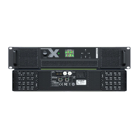
Maxx/D² Front View
Maxx/D² Back View
Dimensions & Weight
Connections & Cable
Mains Supply
Available Power Cords
Ethernet / Dante
Network Modes
Dante Ip Settings
Control Ip Settings
Hostname
Network Services
Madi (Aes10) / Aes3
MADI Optical
MADI Coaxial / AES3
Amp Output
Bridge Mode
Overcurrent Behaviour
Power Distribution
3 Idfm (Firmware Update and Ip Control)
Discovery
Ip Settings
Firmware Storage
Firmware Update
4 DSP (Internal)
5 Frontpannel
Display
Overview
Display Device Lock
Display Menu
Mute
General
Network
Channel
Power Led
6 Website
Header
Pages
Save Internal Storage
Psu Limit
Amp Status
Footer
Overview
Selection and Grouping
Modal Header
Channel Settings
Name
Identify
Bridge Mode
DC Coupling
Power
Auto Standby
Input
Stream
Mute
Channel Volume
Phase
Delay
Peq
PEQ Add / Remove
Advanced Eq (Fir)
Copy to / Copy from
Limit
Look Ahead Delay
Example Settings
Speaker Settings
Analyzer
Measurement
Interfaces
Interface Status
Input
Madi Fibre/Dante Output
Device
Settings
Dante Settings
Time
Psu
Housing
Voltage Reference
Device Mute
Remote Mute
Website Password
Device Reboot
Mutegroups
Presets
Logging
Metering
7 Error Codes
8 Restful API
Get Device Infomrations
Set Channel Mute
Get Channel Volume Options
Remove Preset with Name Test
9 Service
Fuses
Firmware Update
Filter Cleaning
Spare Parts
10 Disposing
11 EU Declaration of Conformity
55032:2012
55103-2
62368-1:2014/Ac:2015
Manufacturer
12 FCC Declaration of Conformity
Advertisement
Quick Links
Download this manual
MAXX SERIES
MA32 D
2
2
2
MA16 D
MA24 D
MA N UA L
+49 (0) 9561 74599-80
innosonix.de
info@innosonix.de
Table of
Contents
Previous
Page
Next
Page
1
2
3
4
5
Advertisement
Table of Contents
Need help?
Do you have a question about the MA16 D2 and is the answer not in the manual?
Ask a question
Questions and answers
Subscribe to Our Youtube Channel
Related Manuals for Innosonix MA16 D2
Amplifier Innosonix MA16 LP2 Manual
(102 pages)
Amplifier Innosonix MA16 HP2 Manual
(100 pages)
Amplifier Innosonix MAXX Series Manual
Digital power amplifiers (91 pages)
Amplifier Innosonix MAXX Series User Manual
(64 pages)
Amplifier Innosonix MA32 LP2 Manual
(102 pages)
Amplifier Innosonix MA32 D2 Manual
(100 pages)
This manual is also suitable for:
Maxx series
Ma24 d2
Ma32 d2
Table of Contents
Print
Rename the bookmark
Delete bookmark?
Delete from my manuals?
Login
Sign In
OR
Sign in with Facebook
Sign in with Google
Upload manual
Upload from disk
Upload from URL


Need help?
Do you have a question about the MA16 D2 and is the answer not in the manual?
Questions and answers