Table of Contents

Subscribe to Our Youtube Channel
Related Manuals for Fluke Biomedical Impulse 6000D


Summary of Contents for Fluke Biomedical Impulse 6000D
- Page 1 Impulse 6000D Defibrillator Analyzer Impulse 7000DP Defibrillator/Transcutaneous Pacer Analyzer Users Manual August 2007, Rev. 1, 1/08 © 2007 Fluke Corporation, All rights reserved. All product names are trademarks of their respective companies.
- Page 2 Fluke Biomedical warrants this instrument against defects in materials and workmanship for one year from the date of origi- nal purchase OR two years if at the end of your first year you send the instrument to a Fluke Biomedical service center for calibration.
- Page 3 Copyright Release Fluke Biomedical agrees to a limited copyright release that allows you to reproduce manuals and other printed materials for use in service training programs and other technical publications. If you would like other reproductions or distributions, submit a written request to Fluke Biomedical.
- Page 4 All items being returned (including all warranty-claim shipments) must be sent freight-prepaid to our factory location. When you return an instrument to Fluke Biomedical, we recommend using United Parcel Service, Federal Express, or Air Parcel Post. We also recommend that you insure your shipment for its actual replacement cost.
- Page 5 Certification This instrument was thoroughly tested and inspected. It was found to meet Fluke Biomedical’s manufacturing specifications when it was shipped from the factory. Calibration measurements are traceable to the National Institute of Standards and Technology (NIST). Devices for which there are no NIST calibra- tion standards are measured against in-house performance standards using accepted test procedures.
- Page 6 Restrictions and Liabilities Information in this document is subject to change and does not represent a commitment by Fluke Biomedical. Changes made to the information in this document will be incorporated in new editions of the publication. No responsibility is assumed by Fluke Biomedical for the use or reliability of software or equipment that is not supplied by Fluke Biomedical, or by its affiliated dealers.
-
Page 7: Table Of Contents
Table of Contents Title Page Defibrillator Analyzer .......................1 Introduction ........................1 Intended Use ........................1 Unpacking the Analyzer ....................1 Safety Information ......................2 Instrument Familiarization ....................4 Turning the Analyzer On and Off..................7 Accessing the Analyzer Tests ..................8 Analyzing Defibrillators....................8 Testing Energy Levels ....................8 Testing Defibrillator Synchronization .................10 Testing Defibrillator Charge Time ................11 Analyzing Pacemakers (7000DP only) ................12... - Page 8 7000DP, 6000D Users Manual Performing a Pacer Demand Test................15 Performing a Pacer Sensitivity Test ................16 Performing a Pacer Refractory Period Test .............. 17 Simulating ECG Signals....................18 Connecting to the ECG Terminals................19 Setting a Normal Sinus Rhythm ECG Signal ............19 Setting a Performance ECG Signal................
- Page 9 Contents (continued) Appendix A - Impulse 6000D/7000DP Remote Operation .............41 Ansur Test Guide ......................41 Defibrillator Tests ......................43 Energy Measurement Test ..................43 Charge Time Test......................45 Sync Time Test......................45 Pacemaker Tests ......................46 Pacer Parameter Test ....................46 Pacer Refractory Test....................46 Pacer Sensitivity Test ....................47 Pacer Demand Mode Test..................47...
- Page 10 7000DP, 6000D Users Manual Energy Measurement Test..................60 Charge Time Test ..................... 62 Synchronization Time Test..................63 Using Pacemaker Test Elements (Impulse 7000DP only) ..........64 Pacer Parameter Test ....................64 Pacer Refractory Test ....................66 Pacer Sensitivity Test....................67 ECG Pacer Interactive Test ..................
- Page 11 List of Tables Table Title Page Symbols..........................2 Top-Panel Controls and Connections..................5 Rear-Panel Connections ....................... 7 Accessories ........................... 29 Energy Measurement Test Measurements................61 Energy Measurement Test Custom Parameters ..............61 Charge Time Test Measurements ..................62 Charge Time Test Custom Parameters ................. 63 Synchronization Time Test Measurements ................
- Page 12 7000DP, 6000D Users Manual Pacer Demand Mode Test Custom Parameters ..............70 Normal Sinus Wave Simulation Test Custom Parameters ............ 71 Arrhythmia Wave Advisory Test Custom Parameters ............72 Performance Wave Simulation Test Custom Parameters ............. 73 ECG R-Wave Test Custom Parameters ................74 ECG Noise Immunity Test Custom Parameters..............
- Page 13 List of Figures Figure Title Page Top-Panel Controls and Connections..................4 Rear-Panel Connections ....................... 6 Analyzer Ready Display ......................7 Defibrillator Menu ........................8 Cursor Navigation Example....................8 Defibrillator Test Connections ....................9 Defibrillator Energy Test ......................10 Defibrillator Synchronization Test ..................10 Defibrillator Charge Time Test....................
- Page 14 7000DP, 6000D Users Manual ECG Main Menu ........................19 Normal Sinus Rhythm Rate Selection................... 19 ECG Connections ......................... 20 Performance Wave Selection....................21 Pacer Simulation Interactive Setup Screen................21 Ventricular Parameter Selection ................... 22 TV Paced Selection ......................23 AV Sequential Screen ......................23 R Wave Detection Screen.....................
-
Page 15: Defibrillator Analyzer
Defibrillator Analyzer Introduction Unpacking the Analyzer The Impulse 6000D and 7000DP (hereafter the Analyzer) Carefully unpack all items from the box and check that are portable, battery-powered precision instruments for you have the following items: testing external defibrillators. The 7000DP has the added •... -
Page 16: Safety Information
Impulse 6000D, 7000DP Users Manual Table 1. Symbols Safety Information In this manual, a Warning identifies hazardous conditions Symbol Description and actions that could cause bodily harm or death. A Important information; refer to manual. Caution identifies conditions and actions that could... - Page 17 Defibrillator/Transcutaneous Pacemaker Analyzer Safety Information • Do not operate the Analyzer with the battery eliminator connected, unless connected directly to mains power. During battery operation, completely remove the battery eliminator/charger from both the Analyzer and wall socket. • Do not connect the Analyzer to a patient or equipment connected to a patient.
-
Page 18: Instrument Familiarization
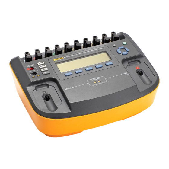
Impulse 6000D, 7000DP Users Manual Instrument Familiarization Figure 1 and Table 2 describes the top-panel controls and connections of the Analyzer. 275 V MAX DEFIBRILLATOR 5000 Vp MAX fak07.eps Figure 1. Top-Panel Controls and Connections... - Page 19 Defibrillator/Transcutaneous Pacemaker Analyzer Instrument Familiarization Table 2. Top-Panel Controls and Connections Item Name Description Outputs of low-level ECG signals (RA/R, LL/F, LA/L, RL/N, V1/C1, V2/C2, V3/C3, V4/C4, ECG lead connectors V5/C5, and V6/C6). Backlight button Turns the LCD display backlight on and off. Power button Turns the Analyzer on and off.
- Page 20 Impulse 6000D, 7000DP Users Manual Figure 2 and Table 3 describes the rear-panel connections of the Analyzer. CHARGE ST ATUS SERIAL NUMBER SCOPE HIGH LEVEL ECG OUTPUT OUTPUT COMPUTER 15 VDC / 1.5 A FLUKE BIOMEDICAL PORT 6920 SEAWAY BLVD EVERETT, WA 98203 www.flukebiomedical.com...
-
Page 21: Turning The Analyzer On And Off
Defibrillator/Transcutaneous Pacemaker Analyzer Turning the Analyzer On and Off Table 3. Rear-Panel Connections Item Name Description Indicates RED while battery is charging. Indicates GREEN when the battery is fully Charge Status LED charged and the charger is still connected. Battery Charger Input connector for attaching the battery charger to the Analyzer. -
Page 22: Accessing The Analyzer Tests
Impulse 6000D, 7000DP Users Manual Accessing the Analyzer Tests The Analyzer uses a series of menus to access various Analyzer functions and setup variables. As shown in Figure 4, the Analyzer indicates three different defibrillator fak03.eps tests (Energy, Sync, and Charge Time) along the bottom Figure 5. - Page 23 Defibrillator/Transcutaneous Pacemaker Analyzer Analyzing Defibrillators DEFIB Defibrillator/Pacer PACER fak11.eps Figure 6. Defibrillator Test Connections...
-
Page 24: Testing Defibrillator Synchronization
Impulse 6000D, 7000DP Users Manual depending on the defibrillator type tested. For dc Monophasic: peak voltage, peak current and pulse width. For dc bi-phasic: peak and average voltage, peak and average current, pulse width, interphase delay, and overall tilt. For ac bi-phasic: all dc bi-phasic data and ac carrier base frequency and duty cycle. -
Page 25: Testing Defibrillator Charge Time
Defibrillator/Transcutaneous Pacemaker Analyzer Analyzing Defibrillators the time from the ECG heart beat ‘R’ wave to the onset of From the Defibrillator main menu, press the softkey the defibrillator pulse. labeled Charge Time. As shown in Figure 9, the waveform selection is already set and Measure Charge If the waveform characteristics are not correct, then Time…... -
Page 26: Analyzing Pacemakers (7000Dp Only)
Impulse 6000D, 7000DP Users Manual The Analyzer senses the discharge and the charge time Setting Up the Analyzer for Pacer Testing appears in the display. Press the softkey labeled Measure W Caution to perform another charge time test. To avoid damage to the Analyzer or... - Page 27 Defibrillator/Transcutaneous Pacemaker Analyzer Analyzing Pacemakers (7000DP only) Defibrillator/Pacer 7000DP Only DEFIB PACER 50 Ω Only 50 - 1500 Ω Caution To avoid damage to the Analyzer or defibrillator, do not apply defibrillator pulses to the pacer inputs. fak10.eps Figure 11. Connecting a Pacemaker to the Analyzer...
-
Page 28: Performing A Pacer Asynchronous Test
Impulse 6000D, 7000DP Users Manual When all three pacer setup variables are set to their Press the softkey labeled Brand to activate the brand list desired values, press the softkey labeled Done. The and scroll through the list using G or H. When the correct... -
Page 29: Performing A Pacer Demand Test
Defibrillator/Transcutaneous Pacemaker Analyzer Analyzing Pacemakers (7000DP only) When testing the attached pacemaker, operating in the above the Underdrive softkey label. To change the underdrive rate, press G or H. continuous (or non-demand) mode, output should be active (ON) when either the “underdrive” ECG signal or The Summary softkey appears after changing the output “overdrive”... -
Page 30: Performing A Pacer Sensitivity Test
Impulse 6000D, 7000DP Users Manual Next, press the softkey labeled Demand. Pressing the increased in very small steps until the pacemaker senses softkey labeled Overdrive causes the Analyzer’s ECG it and inhibits the output pulse. signal to jump to the rate shown above the Overdrive To perform a Pacer Sensitivity test, press the softkey softkey label. -
Page 31: Performing A Pacer Refractory Period Test
Defibrillator/Transcutaneous Pacemaker Analyzer Analyzing Pacemakers (7000DP only) labeled Summary displays a summary of the test which Pacing Rate Interval can be uploaded to a PC. @ 80 BPM=750 mS Performing a Pacer Refractory Period Test This test is composed of two related quantifiable tests that determine the demand mode pacemaker’s ability to sense Cardiac Test Pulse ECG activity immediately following either a paced event... -
Page 32: Simulating Ecg Signals
Impulse 6000D, 7000DP Users Manual Sensed Refractory Period (SRP) Pacing Rate Interval The Analyzer next generates a second simulated ECG Reset > 750 mS signal immediately trailing the first simulated ECG signal used to determine the PRP. See Figure 17. This coupling interval is slowly extended until the simulated ECG signal falls outside the PRP. -
Page 33: Connecting To The Ecg Terminals
Defibrillator/Transcutaneous Pacemaker Analyzer Simulating ECG Signals Note If noise is present in the ECG with the battery charger plugged in, unplug it from the charger to correct the problem. fak19.eps Figure 19. Normal Sinus Rhythm Rate Selection To set the amplitude of the ECG signal, press the softkey labeled Amplitude. - Page 34 Impulse 6000D, 7000DP Users Manual ECG Monitor fak09.eps Figure 20. ECG Connections...
-
Page 35: Setting Pacer Interactive Ecg Waves (7000Dp Only)
Defibrillator/Transcutaneous Pacemaker Analyzer Simulating ECG Signals Setting the ECG Signal for an Interactive ECG/Pacer The performance signal controls consist of a waveform Demand Mode Simulation selection, amplitude, and frequency or rate settings. To select a performance waveform, press the softkey labeled From the ECG main menu, press the softkey labeled Wave Form. -
Page 36: Selecting Ecg Arrhythmias
Impulse 6000D, 7000DP Users Manual Setting the Analyzer for an Interactive ECG/Pacer the softkey labeled More. Three arrhythmia selections are Asystole Mode Simulation displayed above the softkeys: Supraventricular, Premature, and Ventricular. Pressing the softkey labeled From the ECG main menu, press the softkey labeled More again, displays the Conduction arrhythmia Pacer Interactive. -
Page 37: Selecting Tv Paced
Defibrillator/Transcutaneous Pacemaker Analyzer Simulating ECG Signals amplitude, press the softkey labeled Amplitude and use G or H to scroll through the amplitude selections. Pressing the softkey labeled Back moves back to the ECG main menu. fak22.eps Selecting TV Paced Figure 25. AV Sequential Screen From the ECG main menu, press the softkey labeled More Testing R Wave Detection twice to display the TV Paced selection over one of the... -
Page 38: Performing A Noise Immunity Test
Impulse 6000D, 7000DP Users Manual Performing a Noise Immunity Test The softkey labeled Line Frequency toggles the frequency of the noise signal between 50 and 60 Hz. This qualitative test verifies the pacemaker’s ability to filter line frequency noise at either 50 or 60 Hz, and sense a Pressing the softkey labeled Amplitude, activates the simultaneously applied simulated ECG signal. -
Page 39: Setting Up The Display
Defibrillator/Transcutaneous Pacemaker Analyzer Setting Analyzer Setup Functions or more hours and the charge value indicates less than 95%. To train the battery, the Analyzer will need to be plugged into the battery charger for up to 15 hours without being used. -
Page 40: Setting Up Sound
Impulse 6000D, 7000DP Users Manual Setting the Display Contrast Next, pressing the softkey labeled Beeper simply toggles the beeper on or off. Pressing the softkey labeled Volume The Analyzer’s display contrast can be set in one of two opens a scroll box above the softkey label. Use G or H ways. -
Page 41: Maintenance
Cleaning the Analyzer simulators supported by an Ansur plug-in. W Caution When you purchase a new Fluke Biomedical analyzer or simulator, you can update your existing Ansur software by Do not pour fluid onto the Analyzer surface; installing a new plug-in. Each plug-in module allows you to... -
Page 42: Maintaining Peak Battery Condition
Impulse 6000D, 7000DP Users Manual W Caution Do not use spray cleaners on the Analyzer; such action may force cleaning fluid into the Analyzer and damage electronic components. Clean the Analyzer occasionally utilizing a damp cloth and mild detergent. Take care to prevent the entrance of liquids. -
Page 43: Accessories
Defibrillator/Transcutaneous Pacemaker Analyzer Accessories Accessories Table 4 lists the accessories for the Analyzer. Table 4. Accessories Fluke Biomedical Model Item Number GE Medical RESPONDER1500/1700 4mm 3065423 Internal Defib Pdl Contacts 2/set 4mm 3065438 R2 Darox MRL/MDE/NK/Kimberly Clark 4mm 3065450 Med ERS /PhysioControl QUIK COMBO 4mm... -
Page 44: Specifications
Impulse 6000D, 7000DP Users Manual Specifications General Specifications Temperature ° ° Operating ............10 °C to 40 °C (50 F to 104 ° ° Storage..............-20 °C to +60 °C (-4 F to +140 Humidity..............10 % to 90 % non-condensing Display ..............LCD display Communications ...........USB device port for computer control... -
Page 45: Defibrillator Analyzer Specifications
Defibrillator/Transcutaneous Pacemaker Analyzer Specifications Defibrillator Analyzer Specifications Energy Output Measurement Compatible Defibrillator Waveshapes....Lown, Edmark, Trapezoidal, DC Bi-phasic, and AC Pulsed Bi-phasic Note AC Pulsed Bi-Phasic waveform has not been approved in the United States. Autoranged Measurement ........0.1 to 600 J Accuracy 0.1 to 360 J .............±(1 % of reading + 0.1 J) 360 to 600 J ............±(1 % of reading + 0.1 J), typical... - Page 46 Impulse 6000D, 7000DP Users Manual Sample rate............250 kHz (4 μs sample) Maximum Average Power........12 W, equivalent to 10 defib pulses of 360 J every 5 minutes Oscilloscope Output Autorange............2000:1, 400:1 and 80:1: dependant on the range Waveform Playback Output .............BNC Output impedance...........50 Ω...
- Page 47 Defibrillator/Transcutaneous Pacemaker Analyzer Specifications Automated Defibrillator Test ECG Waves Normal Sinus............30 to 300 (by 1) BPM Ventricular Fibrillation..........Coarse and fine Monomorphic Ventricular Tachycardia....120 to 300 (by 5) BPM Polymorphic Ventricular Tachycardia....5 types Asystole...............Flat line ECG Waves ECG General Lead configuration..........12-lead simulation. RA, LL, LA, RL, V1-6 with independent outputs Lead to lead impedance ........1000 Ω...
- Page 48 Impulse 6000D, 7000DP Users Manual Lead V1............24 Lead V2............48 Lead V3............100 Lead V4............120 Lead V5............112 Lead V6............80 ECG Normal Sinus Rates..............10 to 360 (by 1) BPM ECG High Level Output (BNC Jack) Amplitude ............0.2 V/mV of Lead I amplitude Accuracy .............±5 %. 2 Hz Square Wave Output Impedance..........50 Ω...
- Page 49 Defibrillator/Transcutaneous Pacemaker Analyzer Specifications Noise Immunity Wave ..............Sine Line Frequency............50 or 60 Hz (± 0.5 Hz) Amplitude ............0.0 to 10.0 (by 0.5) mV Accuracy..............± 5% Transvenous Pacer Pulse Simulation Widths Range..............0.1, 0.2, 0.5, 1.0, and 2.0 ms Accuracy............±5 % of setting Amplitudes............0 (off) and ±2, ±4, ±6, ±8, ±10, ±12, ±14, ±16, ±18, ±20, ±50, ±100, ±200, ±500, and ±700 mV Accuracy..............±...
- Page 50 Impulse 6000D, 7000DP Users Manual Paroxysmal Atrial Tachycardia (PAT) Nodal Rhythm Supraventricular Tachycardia Premature Atrial PAC Nodal PNC PVC1 Left Ventricle PVC1 LV Early PVC1 LV R on T PVC2 Right Ventricle PVC2 RV Early PVC2 RV R on T...
- Page 51 Defibrillator/Transcutaneous Pacemaker Analyzer Specifications Asystole Conduction 1° Block 2° Block Type I 2° Block Type II 3° Block Right Bundle Branch Block RBBB Left Bundle Branch Block LBBB Transvenous Paced with selectable pacer spike amplitudes and widths Atrial 80 BPM Async 75 BPM Demand with frequent sinus beats Demand with occasional sinus beats...
-
Page 52: Transcutaneous Pacemaker Analyzer Specifications (Impulse 7000Dp Only)
Impulse 6000D, 7000DP Users Manual Transcutaneous Pacemaker Analyzer Specifications (Impulse 7000DP only) Test Load Selections Defibrillator Input Fixed Load ............50 Ω Accuracy .............±1 %, non-inductive (<2 μH) Power Rating............10 defib pulses of 360 J every 5 minutes Pacemaker Input Variable Load ............50 to 1500 Ω in 50 Ω steps Accuracy .............±1 %, non-inductive (<2 μH) - Page 53 Defibrillator/Transcutaneous Pacemaker Analyzer Specifications Pulse Rate Range..............5.0 to 800 PPM Accuracy..............±(0.5% of reading + 0.1 PPM) Pulse Width Range..............1.00 to 100.0 ms Accuracy..............±(0.5% of reading + 0.01 ms) Energy Range..............1 µJ to 2.00 J Accuracy..............±(4% of reading + 10 µJ) Demand and Asynchronous Mode Test Input Pacer pulse rates.........30 to 200 PPM ECG NSR wave...
- Page 54 Impulse 6000D, 7000DP Users Manual Sensitivity Test Automatic Interactive Threshold Detection Compatible pacer rates ........30 to 120 PPM ECG R wave: Waveforms ............Square, Triangle, Sine Width ..............1 to 19 (by 1) ms 20 to 95 (by 5) ms 100 to 300 (by 25) ms Accuracy .............±...
-
Page 55: Appendix A - Impulse 6000D/7000Dp Remote Operation
Analyzer. energy level for the DUT, in this case a defibrillator. Press When a test is executed with the Impulse 6000D/7000DP Start on the TEST GUIDE toolbar to begin the test. Plug-in, the TEST GUIDE window opens. Use the TEST... - Page 56 Impulse 6000D, 7000DP Users Manual fcz06.bmp Figure 30. Ansur Test Guide Window...
-
Page 57: Defibrillator Tests
Wait for Ansur to finish configuring the Defibrillator Tests Analyzer. The Impulse 6000D/7000DP Plug-in allows testomg of When configuration is complete, a window displays defibrillator performance using a PC running the Ansur the prompt to discharge the defibrillator. - Page 58 Impulse 6000D, 7000DP Users Manual fcz07.bmp Figure 31. Graph of Discharge Curve...
-
Page 59: Charge Time Test
Defibrillator/Transcutaneous Pacemaker Analyzer Defibrillator Tests When charging is complete, discharge the Charge Time Test defibrillator. Test results appear in the Test results The Charge Time test measures how long it takes to pane. charge the defibrillator to a specified energy level. This Sync Time Test test should use the defibrillator’s maximum available energy level. -
Page 60: Pacemaker Tests
Impulse 6000D, 7000DP Users Manual Discharge the defibrillator. Results of the test appear Click Stop in the TEST GUIDE toolbar to conclude in the Test results pane. the test. Click Next to proceed or click Start to run the test Pacemaker Tests again. -
Page 61: Pacer Sensitivity Test
Defibrillator/Transcutaneous Pacemaker Analyzer Pacemaker Tests vary in rate and making several timing When the Analyzer has completed measurements, measurements on how the pacer responds. For this Ansur retrieves the results and displays them in the reason, the test typically takes 1 - 2 minutes to Test results pane. -
Page 62: Asynchronous Mode Test
Impulse 6000D, 7000DP Users Manual Asynchronous Mode Test ECG Waveform Simulation Tests This test follows the same procedure as the Pacer The ECG Waveform tests are used to verify the correct Demand Mode but is run with the pacer in non-demand operation of an ECG monitor. -
Page 63: Arrhythmia Wave Test
Defibrillator/Transcutaneous Pacemaker Analyzer ECG Waveform Simulation Tests the BPM is outside the limits specified in the test Performance Wave Simulation procedure, the test is automatically marked as failed. The Performance Wave simulation tests the integrity of a defibrillator monitor using a variety of additional waveform Arrhythmia Wave Test shapes such as square, triangle, sine, and pulse. -
Page 64: Ecg Noise Immunity Test
Impulse 6000D, 7000DP Users Manual Click the Test passed checkbox or the Test failed Battery Capacity Test checkbox to record the observed result of the test. The Battery Capacity test can be used to check whether a battery-powered defibrillator can deliver a certain number... -
Page 65: Defib Pulse Repetition Test
Defibrillator/Transcutaneous Pacemaker Analyzer Battery Performance Tests When charging is complete, discharge the Set the defibrillator to the energy level indicated in defibrillator. The first test result briefly appears in the the information block in the right pane of the TEST right pane of the TEST GUIDE window. - Page 66 Impulse 6000D, 7000DP Users Manual...
-
Page 67: Appendix B - Impulse 6000D/7000Dp Test Templates
Ansur by the user. This chapter introduces the template capabilities of the To build a test template, take the following actions, Impulse 6000D/7000DP Plug-In and provides guidance beginning from the Main Application window: for customizing test templates. Creating Test Templates... - Page 68 Impulse 6000D, 7000DP Users Manual fcz08.bmp Figure 32. Test Template with Selected Test Element...
- Page 69 Defibrillator/Transcutaneous Pacemaker Analyzer Creating Test Templates In the middle of the Test Template window are Test element properties consist of multiple pages, located the following tabs to allow definition of the described below. properties of the highlighted test element. Click the General setup tab. A screen opens, •...
- Page 70 Impulse 6000D, 7000DP Users Manual Note Click the Apply when tab to assign report levels, standards, and service events to test elements. The Expected results page is unavailable when test elements do not return measurement data. Click the Expected results tab to view or change the measurement limits for tests, as shown in Figure 34.
- Page 71 Defibrillator/Transcutaneous Pacemaker Analyzer Creating Test Templates • X + (X * Y%) – calculated as a percentage To define how Ansur calculates the limit values for deviance from the preset value certain measurements, click the Operand field to open a drop-down menu, as shown in Figure 2-35. When the operand is not an absolute limit, the (dynamic) icon appears in the left column, as The operand can be set to any of the following:...
- Page 72 Impulse 6000D, 7000DP Users Manual To add or delete limits, right click one of the rows of up menu, as shown in Figure 36. the Expected results page and select from the pop- fcz12.bmp Figure 36. Add or Delete Limits Pop-up Menu...
- Page 73 Defibrillator/Transcutaneous Pacemaker Analyzer Creating Test Templates Not Applicable (NA) while the tests run. The Skip and Click the Custom setup tab to view and define the NA buttons, shown below, are enabled by default. If parameters used in tests. Test elements have unique a setting is enabled, the corresponding Skip or NA custom setups for the capabilities they provide.
-
Page 74: Using Defibrillator Test Elements
Impulse 6000D, 7000DP Users Manual Note Defibrillator tests also have available the Auto Advance option that is disabled by default. This This test element supports the Auto Advance option advances the Test Guide to the next Test Guide Setting. defibrillator test step automatically. If this option is... - Page 75 Defibrillator/Transcutaneous Pacemaker Analyzer Using Defibrillator Test Elements Table 5. Energy Measurement Test Measurements Measurement Unit of Measure Description Energy Joules Amount of energy discharged by the defibrillator Peak Voltage Volts Peak voltage detected during the discharge Peak Current Amperes Peak current detected during the discharge Pulse Width 50% milliseconds The width of the pulse at 50% of its peak...
-
Page 76: Charge Time Test
Impulse 6000D, 7000DP Users Manual measurements taken for this test. Custom parameters Charge Time Test available for the Charge Time tests are listed in Table 8. The Charge Time test measures how long a defibrillator Note takes to charge up to a specified energy level. Typically,... -
Page 77: Synchronization Time Test
Defibrillator/Transcutaneous Pacemaker Analyzer Using Defibrillator Test Elements Table 8. Charge Time Test Custom Parameters Parameter Description Preset Energy The energy (in Joules) used for the test The field user is prompted to set the defibrillator to this value. ECG Waveform The ECG waveform that the Analyzer should simulate during the test listed in Table 9. -
Page 78: Using Pacemaker Test Elements (Impulse 7000Dp Only)
Tables Pacemaker tests confirm the basic operation of external 11 and 12 list the Pacer Parameter test measurements transcutaneous pacemakers by measuring various and custom parameters. pacemaker outputs and timing. These tests do not operate with the Impulse 6000D analyzer. - Page 79 Defibrillator/Transcutaneous Pacemaker Analyzer Using Pacemaker Test Elements (Impulse 7000DP only) Table 11. Pacer Parameter Test Measurements Measurement Unit of Measure Description Pacer Rate Pulses/minute Number of pacer pulses detected by the Analyzer during the test Pulse Amplitude milliamperes Peak current detected during the test Pulse Width milliseconds Pacer pulse width as measured by the Analyzer...
-
Page 80: Pacer Refractory Test
Impulse 6000D, 7000DP Users Manual Pulsed Refractory Period (PRP) and the Sensed Pacer Refractory Test Refractory Period (SRP) timings as measured by the The Pacer Refractory test checks the ability of the Analyzer. Tables 13 and 14 list the Pacer Refractory test pacemaker to interact with cardiac activity when the measurements and custom parameters. -
Page 81: Pacer Sensitivity Test
Defibrillator/Transcutaneous Pacemaker Analyzer Using Pacemaker Test Elements (Impulse 7000DP only) Table 14. Pacer Refractory Test Custom Parameters Parameter Description Input Jacks Specifies where the pacer leads are attached on the Impulse 7000 Choose between pacer jacks or defib jacks. Pacer Load Defines load used for the test If defib jacks are used for the test, a 50 Ω... -
Page 82: Ecg Pacer Interactive Test
Impulse 6000D, 7000DP Users Manual Table 16. Pacer Sensitivity Test Custom Parameters Parameter Description Input Jacks Specifies where the pacer leads are attached on the Impulse 7000DP Choose between pacer jacks or defibrillator jacks. Pacer Load Defines load used for the test If defibrillator jacks are used for the test, a fixed 50 Ω... - Page 83 Defibrillator/Transcutaneous Pacemaker Analyzer Using Pacemaker Test Elements (Impulse 7000DP only) Table 17. ECG Pacer Interactive Test Custom Parameters Parameter Description Response Waveform The type of patient response to simulate: • Demand: Normal sinus rhythm at specified rate. Pacer in demand mode can interact so it paces when the normal rate is too slow.
-
Page 84: Pacer Demand Mode Test
Impulse 6000D, 7000DP Users Manual Note Pacer Demand Mode Test This is a visual / audible test; the Analyzer takes The Pacer Demand Mode test is used to verify demand no measurements during this test. mode pacing over a range of BPM rates. This test is conducted as a pass/fail test. -
Page 85: Asynchronous Mode Test
Defibrillator/Transcutaneous Pacemaker Analyzer Using ECG Waveform Simulation Test Elements Using ECG Waveform Simulation Test Asynchronous Mode Test Elements The Asynchronous Mode Test element requires the same parameters as the Pacer Demand Mode Test, but this Normal Sinus Wave Simulation test element is used for testing a non-demand mode The Analyzer can generate a normal sinus wave between pacer. -
Page 86: Arrhythmia Wave Test
Impulse 6000D, 7000DP Users Manual Note Arrhythmia Wave Test This is a visual / audible test; the Analyzer takes This test is typically used to verify the shock advisory no measurements during this test. capability of a defibrillator in response to various arrhythmia waveforms. -
Page 87: Performance Wave Simulation
Defibrillator/Transcutaneous Pacemaker Analyzer Using ECG Waveform Simulation Test Elements Note Performance Wave Simulation This is a visual / audible test; the Analyzer takes The Performance Wave simulation can be used to test no measurements during this test. the integrity of a defibrillator monitor with a variety of additional waveform shapes, such as square, triangle, sine, and pulse. -
Page 88: Ecg R-Wave Test
Impulse 6000D, 7000DP Users Manual Note ECG R-Wave Test This is a visual / audible test; the Analyzer takes The ECG R-Wave test checks the ability of the ECG no measurements during this test. monitor to detect an R-Wave over a range of R-Wave widths and amplitudes. -
Page 89: Ecg Noise Immunity Test
Defibrillator/Transcutaneous Pacemaker Analyzer Using Battery Performance Test Elements Note ECG Noise Immunity Test This is a visual / audible test; the Analyzer takes The ECG Noise Immunity test checks the ability of the no measurements during this test. ECG monitor to reject AC line frequency noise. The custom parameters for this test are listed in table 23. - Page 90 Impulse 6000D, 7000DP Users Manual Table 24. Battery Capacity Test Measurements Measurement Unit of Measure Description Charge Time seconds How long it took for the defibrillator to charge to the preset energy specified The test stores multiple charge times – one per discharge.
-
Page 91: Defib Pulse Repetition Test
Defibrillator/Transcutaneous Pacemaker Analyzer Using Battery Performance Test Elements number of discharges within a specified amount of time. Defib Pulse Repetition Test Tables 26 and 27 list the Defib Pulse Repetition test The Defib Pulse Repetition test is used to determine if a measurements and custom parameters. - Page 92 Impulse 6000D, 7000DP Users Manual...
Need help?
Do you have a question about the Impulse 6000D and is the answer not in the manual?
Questions and answers