Table of Contents
Advertisement
Quick Links
A l l t e s t I n s t r u me n t s , I n c .
5 0 0 C e n t r a l A v e .
F a r mi n g d a l e , N J 0 7 7 2 7
P : ( 7 3 2 ) 9 1 9 - 3 3 3 9
F : ( 7 3 2 ) 9 1 9 - 3 3 3 2
a l l t e s t . n e t
s s a l e s @ a l l t e s t . n e t
T h e t e s t & me a s u r e me n t
e q u i p me n t y o u n e e d a t
t h e p r i c e y o u w a n t .
A l l t e s t c a r r i e s t h e w o r l d ' s l a r g e s t s e l e c t i o n o f
u s e d / r e f u r b i s h e d b e n c h t o p t e s t & me a s u r e me n t
e q u i p me n t a t 5 0 % t h e p r i c e o f n e w .
O O u r e q u i p me n t i s g u a r a n t e e d w o r k i n g , w a r r a n t i e d , a n d
a v a i l a b l e w i t h c e r t i f i e d c a l i b r a t i o n f r o m o u r i n - h o u s e s t a f f
o f t e c h n i c i a n s a n d e n g i n e e r s .
• 1 0 + f u l l t i me t e c h n i c i a n s w i t h o v e r 1 5 0 y e a r s o f
s p e c i a l i z a t i o n
• 9 0 d a y w a r r a n t y & 5 d a y r i g h t o f r e t u r n o n a l l
e q u i p me n t
• • 1 - 3 y e a r w a r r a n t i e s f o r n e w a n d
p r e mi u m- r e f u r b i s h e d e q u i p me n t
• E v e r y u n i t t e s t e d t o O E M s p e c i f i c a t i o n s
• S a t i s f a c t i o n g u a r a n t e e d
Y o u h a v e p l a n s , w e w i l l h e l p y o u a c h i e v e t h e m.
A n y p r o j e c t . A n y b u d g e t .
t
G e t a q u o t e t o d a y !
C C a l l ( 7 3 2 ) 9 1 9 - 3 3 3 9 o r e ma i l s a l e s @a l l t e s t . n e t .
Advertisement
Table of Contents

Related Manuals for Fluke Biomedical UW 5


Summary of Contents for Fluke Biomedical UW 5
- Page 1 T h e t e s t & me a s u r e me n t e q u i p me n t y o u n e e d a t t h e p r i c e y o u w a n t . A l l t e s t I n s t r u me n t s , I n c .
- Page 4 UW 5 Digital Ultrasound Wattmeter FBC Products Manual P/N 2635738 February 26, 2006 © 2006 Fluke Corporation, All rights reserved. Printed in USA All product names are trademarks of their respective companies.
- Page 6 Fluke Biomedical. This warranty does not apply if the product has been damaged by accident or misuse or as the result of service or modification by other than Fluke Biomedical. IN NO EVENT SHALL FLUKE BIOMEDICAL BE LIABLE FOR CONSEQUENTIAL DAMAGES.
- Page 7 All Rights Reserved © Copyright 2006, Fluke Biomedical. No part of this publication may be reproduced, transmitted, transcribed, stored in a retrieval system, or translated into any language without the written permission of Fluke Biomedical. Copyright Release Fluke Biomedical agrees to a limited copyright release that allows you to reproduce manuals and other printed materials for use in service training programs and other technical publications.
- Page 8 Biomedical Corporation. Changes made to the information in this document will be incorporated in new editions of the publication. No responsibility is assumed by Fluke Biomedical Corporation for the use or reliability of software or equipment that is not supplied by Fluke Biomedical Corporation, or by its affiliated dealers.
-
Page 9: Safety Considerations
Use of this instrument is restricted to qualified personnel who recognize shock hazards and are familiar with safety precautions used when operating electrical equipment. Read the manual carefully before operating the UW 5. ∗ The following warning and informational symbols may be found on the UW 5: Symbol Description... -
Page 10: Hazard Warnings
UW 5 Hazard Warnings ∗ Warning! Power Rating. The UW 5's mains power input must be connected to an external power transformer that provides voltage and current within the specified rating for the system. Use of an incompatible power transformer may produce electrical shock and fire hazards. -
Page 11: Electromagnetic Interference And Susceptibility
UW 5 Electromagnetic Interference and Susceptibility ∗ USA FCC CLASS A Changes or modifications to this unit not expressly approved by the Warning: manufacturer could void the user's authority to operate the equipment. This equipment has been tested and found to comply with the limits for a Class A digital device, pursuant to Part 15 of the FCC Rules. -
Page 12: Ec Directive 73/23/Eec Low Voltage (User Safety)
UW 5 Based on the testing standards below, this device bears the mark. EC Directive 04/108/EEC Electromagnetic Compatibility ∗ Emissions - CLASS A The system has been type tested by an independent, accredited testing laboratory and found to meet the requirements of EN 61326-1:1998 for Radiated Emissions and Line Conducted Emissions. - Page 13 “Safety Requirements for Electrical Equipment for Measurement, Control and Laboratory Use, Part 1: General requirements” (including amendments 1 & 2). viii...
-
Page 14: Table Of Contents
Safety, Maintenance and Storage..........4-1 Recommended Procedures and Precautions................4-3 Calibration Check Procedures...................... 4-3 Maintenance ..........................4-4 Service............................4-5 Returning the UW 5 for Calibration ..................4-5 Battery Replacement......................4-6 Storage ............................4-6 Repackaging and Shipping......................4-7 Appendix A Troubleshooting ................A-1... -
Page 16: Chapter 1: General Information
Chapter 1: General Information Inside This Chapter • Summary of Features • Ultrasound and its Applications • Patient Treatment with Therapeutic Ultrasound... -
Page 18: Summary Of Features
The instrument measures output through a strain gauge bridge transducer. After the initial output is verified, the UW 5 is used to accurately calibrate the ultrasound unit under test. In addition, the UW 5: •... -
Page 19: Ultrasound And Its Application
Ultrasound and Its Applications Human perception of sound waves is limited to frequencies of fewer than 20,000 vibrations per second. Higher frequency vibrations — between 0.7 and 3.3 MHz — are used for ultrasound therapy. (Most ultrasound equipment produces an output of between 1 and 3.3 MHz.) An ultrasound unit produces electrical oscillations at a specified frequency that cause the transducer in the ultrasound applicator... -
Page 20: Patient Treatment With Therapeutic Ultrasound
another and of changing the tensile strength of tendons, thereby increasing their extensibility. The physiological benefits from ultrasound therapy are numerous. Ultrasound therapy affects the peripheral nerves by chemically changing the conduction velocity (this has been shown clinically in situ). Ultrasound alters the diffusion of Na+ and K+ (sodium and potassium) across red blood cell membranes. -
Page 22: Chapter 2: Description
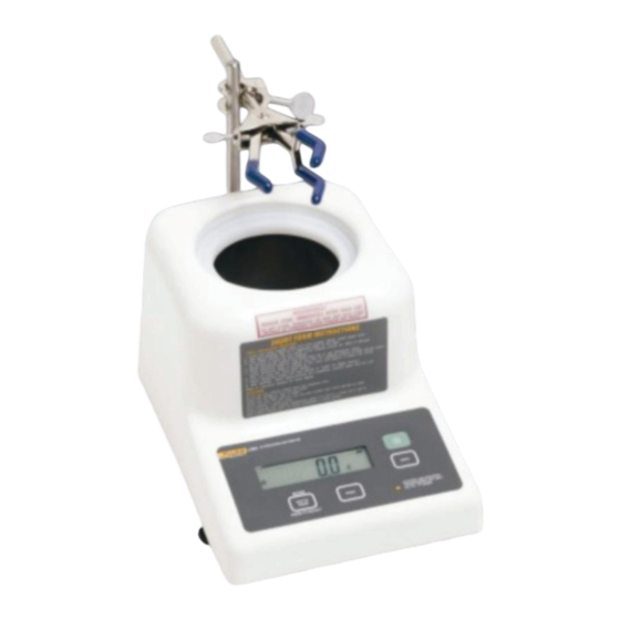
Chapter 2: Description Inside This Chapter • Specifications • Overall Unit Layout • Front Panel Description • Back Panel Description • Standard Accessories • Optional Accessories... - Page 24 7 ½” (10 ¾” with Clamp Post) Case Kydex ® Overall Unit Layout The top of the UW 5 Ultrasound Wattmeter is shown in Figure 2-1. It includes the following components. • Front Panel: Includes LCD readout and keyboard. •...
- Page 25 Front Panel Description The front panel of the UW 5 ultrasound wattmeter is shown in Figure 2-2. It includes the following components. • LCD Display: Indicates the meter reading in watts or grams.
- Page 26 Print Button: Sends the text on screen to the RS-232 port for printing or recording Back Panel Description The back panel of the UW 5 is shown in Figure 2-3. It includes the following components: • Battery Compartment: Allows access to the instrument's 9 V dc battery.
-
Page 27: Bottom Panel Description
Bottom Panel Description The bottom panel of the UW 5 is shown in Figure 2.4. It includes the following components: • Leveling Jacks: There are three support legs located on the bottom panel, two of which are threaded to be able to act as leveling jacks for the height adjustment to level the unit. - Page 28 • Calibration Check Weight: A 100 gram OMIL class M1 weight is included. This to be used to ensure the unit is operating properly and is in allowable calibration range. • Calibration support ring: This ring provides a platform for the 100 gram check weight when checking the unit's calibration and performance.
-
Page 29: Optional Accessories
Optional Accessories • Dissolved Oxygen Test Kit: Tests the dissolved oxygen content of the degassed water. To order this kit, request Fluke PN 2212811. • RS-232 Cable: Used for hooking the unit up to a computer or a serial printer. PN 2238659. •... -
Page 30: Chapter 3: Installation & The Operating Environment
Chapter 3: Installation & The Operating Environment Inside This Chapter • Unpacking and Inspection • Operation • UW 5 Systems Check • Beginning Ultrasound Power Measurements • Ultrasound Unit Testing • Using the RS232 Port... -
Page 32: Unpacking And Inspection
(Refer to Chapter 4 for shipping instructions.) If there is no shipping damage, continue removing the carrying case, with the UW 5 in it, from the shipping case. Then check the carrying case for the following accessories that are shipped with every UW 5: •... - Page 33 • Clamp Support Post • Hook Clamp • 100 gram calibration check weight • Calibration weight adapter pedestal • Centering Rings (3) • 9 Volt Battery • Power Transformer • Manual • Carrying Case...
-
Page 34: Operation
• Do not apply more than 30 W of input power to the UW 5. • Do not operate the UW 5 for more than 1 hour during testing. Change water after one hour of use. • Remove the cone when the test is complete. - Page 35 45 minutes. Exposure to air makes this water lose its excellent coupling property; therefore, the bottles should not be opened until tests with the UW 5 are ready to begin. Be sure to allow water to come to room temperature before use.
-
Page 36: Uw 5 Systems Check
Transformer Unit power jack 3. Allow sufficient time for the UW 5 to fully adjust to room temperature. If the unit is not at room temperature, the transducer will be slowly warming or cooling and will cause the readings to shift. - Page 37 5. Open the bottle of degassed water. When the vacuum seal is broken you should be able to hear it. If you do not hear or feel the vacuum, discard the water. 6. Use a Dissolved Oxygen Test kit to ensure that the oxygen content of the water is less than 2 ppm.
-
Page 38: Beginning Ultrasound Power Measurements
45 minutes to 1 hour. 2. Turn on the UW 5 using the ON switch on the front panel. Ensure that the unit is in the Watts mode (displayed units will read 0). - Page 39 Remove the tube from its clip and raise the tube end above the level of water in the tank before removing the drain cap, to avoid getting wet. 8. Dispose of any water left in the opened bottle of degassed and distilled water. The water will absorb oxygen over time, rendering it ineffective as a coupling medium.
-
Page 40: Using The Universal Transducer Clamp Assembly And Centering Rings
Using the Universal Transducer Clamp Assembly and Centering Rings The universal transducer clamp assembly frees the operator from holding the transducer treatment (radiating) head in the coupling water and prevents transducer movement, ensuring more accurate and stable readings. The centering rings help to properly center and aim the transducer head in the tank. -
Page 41: Ultrasound Unit Testing
Use some form of performance record labels or sheets for record keeping during testing. Testing Using Discrete Values (Method I) 1. Follow the procedures in this section on operating the UW 5. Review the Precautions. 2. Affix a record performance label to the ultrasound unit. -
Page 42: Using The Rs232 Port
4. Record these values under Ultrasound Setting on the label. 5. Measure the output on the UW 5. 6. Record the UW 5 reading under Actual Output in Watts on the performance label. Testing Using Exact Meter Settings (Method II) When this method is used, an exact meter setting is obtained for each power desired. - Page 43 Communications Protocol Communication with the UW 5 is full duplex. There are two commands that may be sent to the UW 5 in the form of two byte 7- bit ASCII strings: Escape P returns the current LCD contents as 22 characters including terminating return and linefeed characters.
-
Page 44: Chapter 4: Safety, Maintenance & Storage
Chapter 4: Safety, Maintenance & Storage Inside This Chapter Recommended Procedures and Precautions Calibration Check Procedures Maintenance Service Returning the UW 5 for Calibration Battery Replacement Storage Repackaging and Shipping... -
Page 46: Recommended Procedures And Precautions
Do not spill water on the front or rear panel. Do not apply more than 30 W of input power to the UW 5. Do not operate the UW 5 for more than 1 hour during testing. Change the water between hour-long tests. -
Page 47: Maintenance
Maintenance Maintenance of the UW 5 Wattmeter is straightforward, requiring little more than keeping it clean. It is important to keep dust and dirt out of the transducer tank. Rinsing the tank with very clean water before use, along with proper storage in the carrying case, is all that is required. -
Page 48: Service
5 and can be performed only at the factory or designated distributor. For service, pack the UW 5 according to the Storage and Shipping instructions in this chapter. Failure to do so may void warranty. Call Fluke Customer Service at 1-888-993-5853 for shipping instructions. -
Page 49: Battery Replacement
Storage The UW 5 must be stored in an upright position on a flat surface that is relatively free of vibration. The unit should be stored in the carrying bag supplied with the unit. The storage environment should be free of dust and other foreign particles. -
Page 50: Repackaging And Shipping
Repackaging and Shipping When the UW 5 is shipped to Fluke for service or repair, the unit should be shipped in its carrying case and the original box with foam inserts. If this original packaging has been damaged or lost, it is strongly recommended that the unit be taken to a professional Pack and Ship service so that it will be adequately cushioned to protect the delicate instrumentation. - Page 51 Transducer Cone. DO NOT SHIP THE UNIT WITH THE CONE IN THE TANK. PERMANENT DAMAGE MAY RESULT AND VOID THE WARRANTY! Place the gray foam-padding insert around the UW 5 unit in the carrying bag. Protective Foam storage ring Operator’s Manual...
- Page 52 4-7. Before the UW 5 is returned to Fluke, make sure you have addressed each item in the following checklist: Obtain a Return Authorization Number from Fluke’s Service Department (1-888-993-5853).
- Page 53 4-10...
-
Page 54: Appendix A: Troubleshooting Guide
Appendix A: Troubleshooting Guide... -
Page 55: Error Codes
Error Codes The UW 5 will display an error code if improper use or an abnormal condition is detected. Consult the following table for possible error codes, the probable cause, and corrective action. Error Description Corrective Action Code Indicates that an under-load is sensed. -
Page 56: Other Problems
RS-232 Port Communication failures between the UW 5 and a printer or a PC are usually caused by the serial cable or incorrect parameter settings. Troubleshoot as follows: 1. Verify that the correct serial cable is being used. The correct cable is Fluke part number 2238659 or equivalent 9-pin “straight-through”... - Page 57 Service Menu Codes, and your unit’s calibration and communications setups could be affected. Call Fluke Biomedical Service Center 1-888-993- 5853 for how to get out of the Service Menu Codes without affecting the operation of your UW 5 and voiding the warranty.
- Page 59 1-888-993-5853...
Need help?
Do you have a question about the UW 5 and is the answer not in the manual?
Questions and answers