Table of Contents

Related Manuals for Fluke Biomedical ESA620


Summary of Contents for Fluke Biomedical ESA620
- Page 1 ESA620 Electrical Safety Analyzer PN 2814971 January 2008, Rev. 3, 5/15 © 2008-2015 Fluke Corporation. All rights reserved. Specifications are subject to change without notice. All product names are trademarks of their respective companies.
- Page 2 Fluke Biomedical warrants this instrument against defects in materials and workmanship for one year from the date of original purchase OR two years if at the end of your first year you send the instrument to a Fluke Biomedical service center for calibration.
- Page 3 Copyright Release Fluke Biomedical agrees to a limited copyright release that allows you to reproduce manuals and other printed materials for use in service training programs and other technical publications. If you would like other reproductions or distributions, submit a written request to Fluke Biomedical.
- Page 4 Fluke Biomedical, we recommend using United Parcel Service, Federal Express, or Air Parcel Post. We also recommend that you insure your shipment for its actual replacement cost. Fluke Biomedical will not be responsible for lost shipments or instruments that are received in damaged condition due to improper packaging or handling.
- Page 5 Restrictions and Liabilities Information in this document is subject to change and does not represent a commitment by Fluke Biomedical. Changes made to the information in this document will be incorporated in new editions of the publication. No responsibility is assumed by Fluke Biomedical for the use or reliability of software or equipment that is not supplied by Fluke Biomedical, or by its affiliated dealers.
-
Page 7: Table Of Contents
Table of Contents Title Page Introduction ........................1 Safety Information ......................3 Intended Use ........................4 Unpacking the Analyzer ....................5 Instrument Familiarization ....................6 Connecting to Line Power ....................9 Connecting a DUT to the Analyzer ................. 9 Turning the Analyzer On ....................11 Adjusting the Display’s Contrast .................. - Page 8 ESA620 Getting Started Manual Specifications ........................ 17 Detailed Specifications ....................18...
- Page 9 List of Tables Table Title Page Symbols ..........................2 Top-Panel Controls and Connections ..................7 Rear-Panel Connections ....................... 9 Replaceable Parts ......................... 14 Accessories ........................... 16...
- Page 10 ESA620 Getting Started Manual...
- Page 11 List of Figures Figure Title Page Top-Panel Controls and Connections ..................6 Rear-Panel Connections ....................... 8 DUT Connections to the Analyzer ..................10 Analyzer Ready for Operation ....................11 Leakage Current Menu ......................11 DUT Ground Resistance Measurement................. 12...
- Page 12 ESA620 Getting Started Manual...
-
Page 13: Introduction
Introduction • Earth (Ground) leakage The Fluke Biomedical ESA620 Electrical Safety Analyzer • Enclosure (Chassis) leakage (hereafter the Analyzer) is a full-featured, compact, • Patient (Lead to Ground) and patient auxiliary portable analyzer, designed to verify the electrical safety (Lead to Lead) leakage of medical devices. -
Page 14: Symbols
ESA620 Getting Started Manual Table 1. Symbols Symbol Description WARNING.RISK OF DANGER. WARNING. HAZARDOUS VOLTAGE. Risk of electric shock. Certified by CSA Group to North American safety standards. Conforms to relevant Australian EMC standards. Conforms to European Union directives ... -
Page 15: Safety Information
Electrical Safety Analyzer Safety Information • Inspect the Analyzer before using it. Do Safety Information not use the Analyzer if abnormal In this manual, a Warning identifies conditions and conditions of any sort are noted (such as procedures that are dangerous to the user. A Caution a faulty display, broken case, etc.) identifies conditions and procedures that can cause •... -
Page 16: Intended Use
ESA620 Getting Started Manual • The Analyzer must be properly earthed. Intended Use Only use a supply socket that has a The Analyzer is intended for use by trained service protective earth contact. If there is any technicians to perform periodic inspections on a wide doubt as to the effectiveness of the range of medical equipment. -
Page 17: Unpacking The Analyzer
This • ESA620 Product is not intended to be used to calibrate medical • Getting Started Manual equipment. -
Page 18: Instrument Familiarization
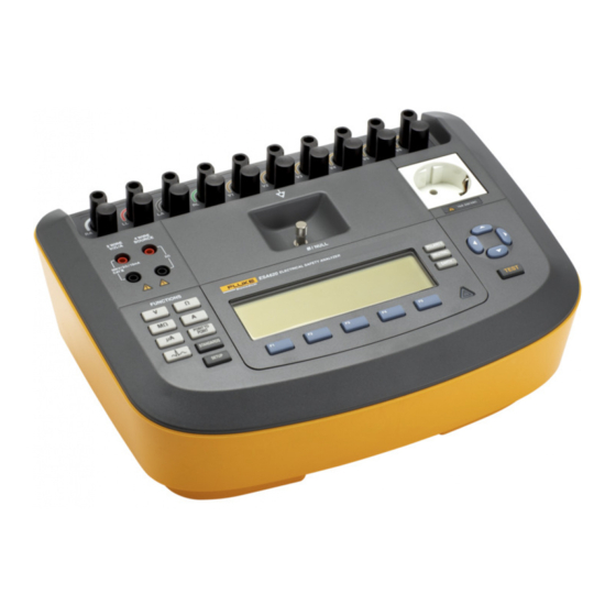
ESA620 Getting Started Manual Instrument Familiarization Figure 1 and Table 2 describe the top-panel controls and connections of the Analyzer. faw02.eps Figure 1. Top-Panel Controls and Connections... -
Page 19: Top-Panel Controls And Connections
Electrical Safety Analyzer Instrument Familiarization Table 2. Top-Panel Controls and Connections Item Name Description Connection posts for Device Under Test (DUT) leads, like ECG leads. Used to test for ECG/Applied Parts leakage current through leads and to supply ECG signals and performance waveforms to a ... -
Page 20: Rear-Panel Connections
ESA620 Getting Started Manual Figure 2 and Table 3 describe the rear-panel connections of the Analyzer. faw01.eps Figure 2. Rear-Panel Connections... -
Page 21: Connecting To Line Power
Electrical Safety Analyzer Connecting to Line Power Table 3. Rear-Panel Connections Item Name Description AC Power Switch Turns ac power on and off A grounded male three-prong (IEC 320 C20) connector that accepts the AC Power Input Connector line-power cord. -
Page 22: Dut Connections To The Analyzer
ESA620 Getting Started Manual faw03.eps Figure 3. DUT Connections to the Analyzer... -
Page 23: Turning The Analyzer On
If the ground is open, the Analyzer displays this fault. If the mains voltage is too high or too low, the Analyzer displays this fault and does not continue until the supply voltage is corrected and the ESA620 power cycled off and then on again. -
Page 24: Dut Ground Resistance Measurement
ESA620 Getting Started Manual In addition to the function softkeys, the Analyzer test Ensure the power cord from the DUT is plugged into functions may require using the navigation buttons to the Analyzer’s test receptacle. select parameters as well. In the example above, the Press ... -
Page 25: What To Do Next
Do not pour fluid onto the Analyzer surface; For more information on how to use the Analyzer, refer to fluid seepage into the electrical circuitry may the ESA620 Users Manual contained on the cause the Analyzer to fail. accompanying CD. -
Page 26: Replaceable Parts
ESA620 Getting Started Manual Replaceable Parts Table 4 list the parts and part numbers of the replaceable parts. Table 4. Replaceable Parts Item Fluke Biomedical Part Number ESA620 Getting Started Manual 2814971 ESA620 Users Manual CD 2814967 2238680 2238596 Australia... - Page 27 Electrical Safety Analyzer Replaceable Parts Table 4. Replaceable Parts (cont.) Item Fluke Biomedical Part Number Null Post Adapter 3326842 Carrying Case 2814980 Data Transfer Cable 1626219 T20A 250V Fuse (Time Lag), 1¼ in x ¼ in 2183691 T10A 250V Fuse (Time Lag), 5 x 20 mm 3046641 ...
-
Page 28: Accessories
Test Leads with retractable sheath 1903307 Kelvin Test Lead Set for 4-wire ground 2067864 Ground Pin Adapters 2242165 ESA620 USA/AUS/ISR Accessory Kit: Test Lead Set 3111008 TP1 Test Probe Set AC285 Alligator Clip Set ESA620 EUR Accessory Kit: Test Lead Set... - Page 29 Electrical Safety Analyzer Specifications Specifications Temperature Operating ............10 °C to 40 °C (50 °F to 104 °F) Storage ..............-20 °C to 60 °C (-4 °F to 140 °F) Humidity ..............10 % to 90 % non-condensing Altitude ..............To 5,000 meters @ 115 V ac mains and ≤150 V measurements To 2,000 meters @ 230 V ac mains and ≤300 V measurements Display ..............
- Page 30 ESA620 Getting Started Manual Class A: Equipment is suitable for use in all establishments other than domestic and those directly connected to a low-voltage power supply network that supplies buildings used for domestic purposes. There may be potential difficulties in ensuring electromagnetic compatibility in other environments due to conducted and radiated disturbances.
- Page 31 Electrical Safety Analyzer Detailed Specifications Accuracy Two Terminal Mode Test current >200 mA ac into 500 mΩ ..±(2 % of reading + 0.015 Ω) for 0.0 to 2.0 Ω Test current 1-16 A ac ......... ±(2 % of reading + 0.015 Ω) for 0.0 to 0.2 Ω ±(5 % of reading + 0.015 Ω) for 0.2 to 2.0 Ω...
- Page 32 ESA620 Getting Started Manual Equipment Current Range ..............0 – 20 A ac rms Accuracy ............. 5 % of reading ±(2 counts or 0.2 A, whichever is greater) Duty cycle ............15 A to 20 A, 5 min. on/5 min. off 10 A to 15 A, 7 min.
- Page 33 Electrical Safety Analyzer Detailed Specifications Mains on applied part test voltage ...... 110 % ±5 % of Mains, current limited to 7.5 mA ±25 % @ 230 V for IEC 60601 100 % ±5 % of Mains for AAMI, current limited to 1 mA ±25 % @ 115 V per AAMI 100 % ±5 % of Mains for 62353 current limited to 3.5 mA ±25 % @ 230 V per 62353 Note For Alternative and Direct applied parts leakage tests, the leakage values are compensated for nominal mains as...
- Page 34 ESA620 Getting Started Manual ECG Performance Waveforms Accuracy ............. ±2 % ±5 % for amplitude of 2 Hz square wave only, fixed @ 1 mV Lead II configuration Waveforms ECG Complex ..........30, 60, 120, 180, and 240 BPM Ventricular Fibrillation Square wave (50 % duty cycle) ......
Need help?
Do you have a question about the ESA620 and is the answer not in the manual?
Questions and answers