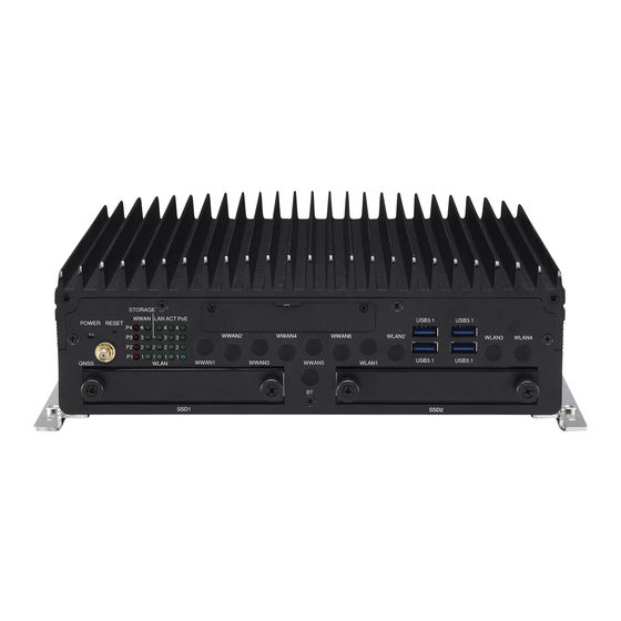
Sign In
Upload
Manuals
Brands
Nexcom Manuals
Desktop
nROK 7251 Series
Nexcom nROK 7251 Series Manuals
Manuals and User Guides for Nexcom nROK 7251 Series. We have
1
Nexcom nROK 7251 Series manual available for free PDF download: User Manual
Nexcom nROK 7251 Series User Manual (105 pages)
Railway Computer
Brand:
Nexcom
| Category:
Desktop
| Size: 10.87 MB
Table of Contents
Table of Contents
2
Acknowledgements
5
Copyright
5
Declaration of Conformity
5
Disclaimer
5
Preface
5
Regulatory Compliance Statements
5
Rohs Compliance
6
Warranty and RMA
7
Conventions Used in this Manual
10
Technical Support and Assistance
10
Global Service Contact Information
11
Package Contents
13
Ordering Information
15
Chapter 1: Product Introduction
16
Nrok 7251-7C4 Physical Features
16
Front View
16
Rear View
16
Nrok 7251-7A Physical Features
17
Front View
17
Rear View
17
Nrok 7251-WI-7C4IP Physical Features
18
Front View
18
Rear View
18
Nrok 7251 Series Hardware Specifications
19
Connector Numbering
22
Nrok 7251-7C4 Front View
22
Nrok 7251-7C4 Rear View
22
Nrok 7251-7A Front View
23
Nrok 7251-7A Rear View
23
Nrok 7251-WI-7C4IP Front View
24
Nrok 7251-WI-7C4IP Rear View
24
Chapter 2: External Connectors Pinout Description
25
Power LED
25
Reset Button
25
LED Indicators (Nrok 7251-7C4/7251-WI-7C4IP)
26
LED Indicators (Nrok 7251-7A)
26
SIM1-1/1-2 to SIM4-1/4-2 Mini-SIM Sockets
27
USB 3.1 Ports
27
M12 Audio Connector
28
HDMI Connector
28
M12 LAN1/2 Connectors (LAN2 for Nrok 7251-7A)
29
Poe1 to Poe4 M12 Connectors (Nrok 7251-7C4 and Nrok 7251-WI-7C4IP)
29
VGA Connector
30
M12 USB 2.0 Connector
30
DIO Connector
31
COM1 RS232 Connector
31
COM2 RS232 Connector
32
COM3 RS232/RS422/RS485 Connector
32
DC Input (Nrok 7251-WI-7C4IP)
33
DC Input (Nrok 7251-7C4 and Nrok 7251-7A)
33
Chapter 3: Jumpers and Switches
34
Before You Begin
34
Precautions
34
Jumper Settings
35
Nrok 7251 Series Connector Specification & Jumper Setting
36
Locations of the Jumpers and Connectors for the Carrier Board
36
DIP Switch and Jumper Settings
37
RTC Clear Selection
37
Input Voltage Setup Selection
37
GPIO Pull Power
38
Internal Connectors
39
GPS Wire to Board Connector
39
GPS Wafer Connector
39
GPS Battery Connector
40
GPS DR in Connector
40
RTC Battery Connector
41
GPIO Connector
41
COM1 RS232 DB9 Connector
42
COM2 RS232 DB9 Connector
42
COM3 RS232/RS422/RS485 DB9 Connector
43
USB Connectors (Reserved)
43
USB Connector (for USB M12 Connector)
44
SATA Connectors
44
MCU Debug Port
45
MCU Download Port
45
DC in Connector
46
Audio Connectors
46
VGA Connector
47
SIM1-1/SIM1-2 to SIM4-1/SIM4-2 Mini-SIM Slots
47
M.2 3042/3050/3052 Key B Socket (USB 2.0, USB 3.1 Gen2) for LTE/5G NR Module with 2 X External SIM
48
M.2 3042/3050/3052 Key B Socket (USB 2.0, USB 3.1 Gen2) for LTE/5G NR Module with 2 X External SIM
49
Full Size Mini-Pcie Socket (USB 2.0) for LTE Module with 2 X External SIM
50
(BOM Optional)
51
M.2 3042 Key B Socket (USB 2.0, USB 3.1 Gen2) for LTE/5G NR Module with 2 X External SIM
51
Full Size Mini-Pcie Socket (USB 2.0, Pcie 3.0/SATA 3.0 [BIOS Selection])
52
Full Size Mini-Pcie Socket (USB 2.0, Pcie 3.0/SATA 3.0 [BIOS Selection])
53
Chapter 4: System Setup
54
Removing the Chassis Cover
54
Installing a SSD/HDD Drive
58
Installing a SO-DIMM Memory Module
60
Removing the Storage Trays before Installing Modules
63
Installing a WLAN Module
65
Installing a WWAN Module (Mini-Pcie)
65
Installing a WWAN Module (M.2)
66
Installing an Msata Module
68
Installing a GPS Module
68
Inserting the SIM Cards
69
Appendix A: Software Demo Utility for I/O Ports of Function Control
70
Menu Screen
70
System 1
70
System 2
72
I/O
73
Module
75
G-Sensor
77
Poe (Nrok 7251-7C4 and Nrok 7251-WI-7C4IP)
78
Event
79
Appendix B: GPS Feature
80
Ublox-NEO M8 Overview
80
Technical Specifications
80
Appendix C: GPS with Dead Reckoning Feature
82
Ublox-NEO M8L Overview
82
Technical Specifications
83
Appendix D: Signal Connection of MCU DI/DO
85
GPIO Pinout Description
85
Digital Input
86
Digital Output
87
CN16 Wlan/Msata Setup
89
Power-On Delay Setting
89
Power-Off Delay Setting
91
CN16 Signal Setting
93
Appendix F: Pin Definition for the Multiport Cable
94
P1 Connector Pinout
95
P2 Connector Pinout
95
GPIO Connector
95
P2 Connector Pinout
97
P1 and P3 Connector Pinouts
97
Green (Line-Out) Connector
97
Pink (MIC-In) Connector
98
CN1 Connector Pinout
100
CN2 and CN3 Connector Pinouts
100
USB Connector
100
USB Connector
101
Appendix G: Power Consumption
102
Advertisement
Advertisement
Related Products
Nexcom nROK 500
Nexcom nROK 6222
Nexcom nROK 1031 Series
Nexcom NISE 104
Nexcom nTUF 600
Nexcom NISE 300
Nexcom NIFE 105 Series
Nexcom NISE 51
Nexcom NISE 108
Nexcom NISE-50-4G-32G
Nexcom Categories
Motherboard
Desktop
Industrial PC
Network Hardware
Digital Signage
More Nexcom Manuals
Login
Sign In
OR
Sign in with Facebook
Sign in with Google
Upload manual
Upload from disk
Upload from URL