Juniper Core Router T Series Hardware Manual
Hide thumbs
Also See for Core Router T Series:
- Monitoring and troubleshooting manual (812 pages) ,
- Handling instructions manual (12 pages)

Related Manuals for Juniper Core Router T Series


Summary of Contents for Juniper Core Router T Series
- Page 1 T320 Core Router Hardware Guide Modified: 2018-07-09 Copyright © 2018, Juniper Networks, Inc.
- Page 2 END USER LICENSE AGREEMENT The Juniper Networks product that is the subject of this technical documentation consists of (or is intended for use with) Juniper Networks software. Use of such software is subject to the terms and conditions of the End User License Agreement (“EULA”) posted at https://www.juniper.net/support/eula/.
-
Page 3: Table Of Contents
Fan Trays ............26 Copyright © 2018, Juniper Networks, Inc. - Page 4 T320 FPC Components ......... . 62 Copyright © 2018, Juniper Networks, Inc.
- Page 5 Ports ............104 Copyright © 2018, Juniper Networks, Inc.
- Page 6 Reinstalling T320 Front Fan Trays ....... . . 149 Reinstalling the T320 Cable Management System ....149 Copyright © 2018, Juniper Networks, Inc.
- Page 7 Removing a Rear T320 Air Filter ........195 Copyright © 2018, Juniper Networks, Inc.
- Page 8 Installing a T320 PIC Cable ........246 viii Copyright © 2018, Juniper Networks, Inc.
- Page 9 Maintaining the T320 SIBs ......... . 286 Copyright © 2018, Juniper Networks, Inc.
- Page 10 Definition of Safety Warning Levels ........325 General Safety Guidelines for Juniper Networks Devices ....327...
- Page 11 T320 General Laser Safety Guidelines ....... . . 343 Laser Safety Warnings for Juniper Networks Devices ..... . 343 Class 1 Laser Product Warning .
- Page 12 DC Power Wiring Terminations Warning ......360 Site Electrical Wiring Guidelines for Juniper Networks Devices ....361 Distance Limitations for Signaling .
- Page 13 Figure 30: T320 Power Supply ........83 Copyright © 2018, Juniper Networks, Inc.
- Page 14 Figure 61: Console and Auxiliary Ports on the CIP ......158 Copyright © 2018, Juniper Networks, Inc.
- Page 15 Figure 100: Installing a PC Card ........228 Figure 101: Removing a T320 Standard Control Board ..... 230 Copyright © 2018, Juniper Networks, Inc.
- Page 16 Figure 134: SIB Serial Number Label ........317 Copyright © 2018, Juniper Networks, Inc.
- Page 17 General Safety Guidelines and Warnings ......325 Figure 135: Placing a Component into an Electrostatic Bag ....330 Copyright © 2018, Juniper Networks, Inc. xvii...
- Page 18 T320 Core Router Hardware Guide xviii Copyright © 2018, Juniper Networks, Inc.
- Page 19 Table 34: T1600 Routing Engines ........57 Copyright © 2018, Juniper Networks, Inc.
- Page 20 Table 60: T320 Open-Frame Rack Mounting Hole Locations ....115 Table 61: T320 Four-Post or Cabinet Rack Mounting Hole Locations ..120 Copyright © 2018, Juniper Networks, Inc.
- Page 21 Table 70: SIB Alarm Messages ........305 Copyright © 2018, Juniper Networks, Inc.
- Page 22 T320 Core Router Hardware Guide xxii Copyright © 2018, Juniper Networks, Inc.
-
Page 23: About The Documentation
® To obtain the most current version of all Juniper Networks technical documentation, see the product documentation page on the Juniper Networks website at https://www.juniper.net/documentation/ If the information in the latest release notes differs from the information in the documentation, follow the product Release Notes. -
Page 24: Table 1: Notice Icons
RFC 1997, BGP Communities Attribute Italic text like this Represents variables (options for which Configure the machine’s domain name: you substitute a value) in commands or [edit] configuration statements. root@# set system domain-name domain-name xxiv Copyright © 2018, Juniper Networks, Inc. -
Page 25: Documentation Feedback
We encourage you to provide feedback, comments, and suggestions so that we can improve the documentation. You can provide feedback by using either of the following methods: Online feedback rating system—On any page of the Juniper Networks TechLibrary site , simply click the stars to rate the https://www.juniper.net/documentation/index.html content, and use the pop-up form to provide us with information about your experience. -
Page 26: Requesting Technical Support
7 days a week, 365 days a year. Self-Help Online Tools and Resources For quick and easy problem resolution, Juniper Networks has designed an online self-service portal called the Customer Support Center (CSC) that provides you with the following features: Find CSC offerings: https://www.juniper.net/customers/support/... - Page 27 About the Documentation For international or direct-dial options in countries without toll-free numbers, see https://www.juniper.net/support/requesting-support.html Copyright © 2018, Juniper Networks, Inc. xxvii...
- Page 28 T320 Core Router Hardware Guide xxviii Copyright © 2018, Juniper Networks, Inc.
-
Page 29: Overview
Cooling System Components and Descriptions on page 25 Host Subsystem Components and Descriptions on page 29 Line Card Components and Descriptions on page 61 Power System Components and Descriptions on page 83 Switch Fabric Components and Descriptions on page 85 Copyright © 2018, Juniper Networks, Inc. - Page 30 T320 Core Router Hardware Guide Copyright © 2018, Juniper Networks, Inc.
-
Page 31: System Overview And Architecture
Junos OS to handle routing protocols, traffic engineering, policy, policing, monitoring, and configuration management. Forwarding operations in the router are performed by the Packet Forwarding Engines, which consist of hardware, including ASICs, designed by Juniper Networks. Copyright © 2018, Juniper Networks, Inc. -
Page 32: T320 Component Redundancy
T320 Switch Interface Boards (SIBs) Description on page 85 T320 Host Subsystem Description on page 29 T320 SONET Clock Generator (SCG) Description on page 19 T320 Power System Description on page 83 T320 Cooling System Description on page 25 Copyright © 2018, Juniper Networks, Inc. -
Page 33: System Architecture Description For T Series Routers
Packet Forwarding Engine. The design of the ASICs allow the forwarding table in the Packet Forwarding Engine to be updated without interrupting forwarding performance. Copyright © 2018, Juniper Networks, Inc. -
Page 34: Figure 2: Control Packet Handling For Routing And Forwarding Table Updates
Related System Architecture Description for T Series Routers on page 5 Documentation Packet Forwarding Engine Architecture for T Series Routers on page 7 Copyright © 2018, Juniper Networks, Inc. -
Page 35: Packet Forwarding Engine Architecture For T Series Routers
To ensure the efficient movement of data, the router is designed so that ASICs on the hardware components handle the forwarding of data. Data flows through the router in the following sequence (see Figure 3 on page Copyright © 2018, Juniper Networks, Inc. -
Page 36: Figure 3: Data Flow Through The Router
Engine. In this case, the notification is sent back to the Switch Interface ASIC facing the outgoing ports, and the packets are sent to the outgoing port without passing through the switch fabric (see Step 13). Copyright © 2018, Juniper Networks, Inc. - Page 37 Layer 2 encapsulation, and sends the packets to the outgoing PIC interface. The outgoing PIC sends the packets out into the network. Related System Architecture Description for T Series Routers on page 5 Documentation Routing Engine Functions for T Series Routers on page 5 Copyright © 2018, Juniper Networks, Inc.
- Page 38 T320 Core Router Hardware Guide Copyright © 2018, Juniper Networks, Inc.
-
Page 39: T320 Router Release Notes
Errata with the T320 Router Documentation on page 11 Documentation Errata with the T320 Router Documentation There are no outstanding issues with the T320 router documentation. Related Outstanding Issues with the T320 Router on page 11 Documentation Copyright © 2018, Juniper Networks, Inc. - Page 40 T320 Core Router Hardware Guide Copyright © 2018, Juniper Networks, Inc.
-
Page 41: Chassis Components And Descriptions
Handles on each side to facilitate positioning the router in the rack. Do not use the handles to lift the router. Two electrostatic discharge (ESD) points (banana plug receptacles), one front and one rear. Copyright © 2018, Juniper Networks, Inc. -
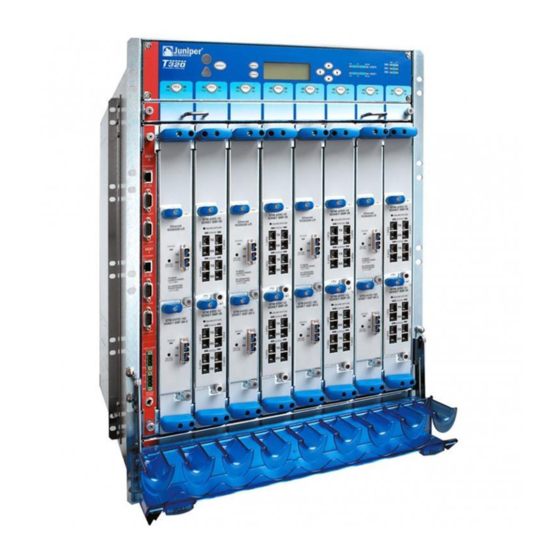
Page 42: Figure 4: Front View Of The T320 Router Chassis
Failure to use an ESD strap could result in damage to the router and its components. Figure 4: Front View of the T320 Router Chassis Copyright © 2018, Juniper Networks, Inc. -
Page 43: T320 Midplane Description
SIBs, Routing Engines, control boards, and SCGs install into the midplane from the rear of the chassis. The power supplies and cooling system components also connect to the midplane. The midplane performs the following major functions: Copyright © 2018, Juniper Networks, Inc. -
Page 44: T320 Connector Interface Panel (Cip) Description
Routing Engines and alarm relay contacts (see Figure 7 on page 17). The front electrostatic discharge point is located near the bottom of the CIP. The CIP is located at the left side of the FPC card cage. Copyright © 2018, Juniper Networks, Inc. -
Page 45: Figure 7: Cip
ACT 1 YEL = 10M GRN = 100M CONSOLE AUXILIARY RED ALARM YELLOW ALARM Related T320 Chassis Description on page 13 Documentation Replacing a T320 CIP T320 Component Serial Number Label Locations on page 312 Copyright © 2018, Juniper Networks, Inc. -
Page 46: T320 Alarm Relay Contacts
This allows you to access the lower fan tray and the front air filter. Figure 8: T320 Cable Management System Related T320 Router Description on page 3 Documentation T320 Chassis Description on page 13 Copyright © 2018, Juniper Networks, Inc. -
Page 47: T320 Sonet Clock Generator (Scg) Description
The external clock inputs are not supported. Related T320 SCG LEDs on page 20 Documentation Maintaining the T320 SCGs on page 273 Replacing a T320 SCG on page 186 T320 Component Serial Number Label Locations on page 312 Copyright © 2018, Juniper Networks, Inc. -
Page 48: T320 Scg Leds
The craft interface allows you to view status and troubleshooting information at a glance and to perform many system control functions. It is hot-insertable and hot-removable. The craft interface is located on the front of the router above the FPCs and contains: Copyright © 2018, Juniper Networks, Inc. -
Page 49: T320 Craft Interface Alarm Leds And Aco/Lt Button
— — Alarm cutoff/lamp test button—Deactivates red and yellow alarms. Causes all LEDs on the craft interface to light (for testing) when pressed and held. Copyright © 2018, Juniper Networks, Inc. -
Page 50: T320 Craft Interface Lcd And Navigation Buttons
When a red or yellow alarm occurs, the LCD switches to alarm mode and reports about the alarm condition, as shown in Figure 12 on page Figure 12: T320 LCD in Alarm Mode The lines in the display report the following information: Copyright © 2018, Juniper Networks, Inc. -
Page 51: T320 Craft Interface Host Subsystem Leds
, are located along the bottom of the craft interface. Table 6 on page 23 describes FPC7 the functions of the FPC LEDs. Table 6: FPC LEDs Label Color State Description FAIL On steadily FPC has failed. Copyright © 2018, Juniper Networks, Inc. -
Page 52: T320 Craft Interface Sib Leds
Table 7: SIB LEDs on the Craft Interface Label Color State Description On steadily SIB has failed. FAIL Green On steadily SIB is functioning normally. Related T320 Chassis Description on page 13 Documentation Replacing a T320 Craft Interface on page 189 Copyright © 2018, Juniper Networks, Inc. -
Page 53: Cooling System Components And Descriptions
Airflow on page 25 Fan Trays on page 26 Air Filters on page 27 Power Supply Cooling System on page 27 Airflow Figure 13 on page 26 shows the airflow through the router. Copyright © 2018, Juniper Networks, Inc. -
Page 54: Fan Trays
The quiet upper front fan tray and quiet lower front fan tray are not interchangeable with each other. In addition to the labels, the quiet upper fan tray also has an upward pointing arrow above the four fan icons on the faceplate. Copyright © 2018, Juniper Networks, Inc. -
Page 55: Air Filters
Each DC power supply contains one fan that cools that power supply. Related Maintaining the T320 Air Filters on page 274 Documentation Maintaining the T320 Fan Trays on page 275 Troubleshooting the T320 Cooling System on page 297 Copyright © 2018, Juniper Networks, Inc. - Page 56 T320 Core Router Hardware Guide Copyright © 2018, Juniper Networks, Inc.
-
Page 57: Host Subsystem Components And Descriptions
Routing Engine requires the corresponding control board, and vice versa. NOTE: We recommend you install two host subsystems for redundant protection. If you install only one host subsystem, we recommend you install it in slot Copyright © 2018, Juniper Networks, Inc. -
Page 58: T320 Control Board Description
A mix of hardware model numbers is supported only during upgrade. Table 8: Supported T320 Control Boards Name Model Number Standard control board (EOL PSN-2006-09-024) CB-L-T T Series control board (T-CB) CB-T Copyright © 2018, Juniper Networks, Inc. -
Page 59: T320 Standard Control Board Description
T320 Standard Control Board and T-CB LEDs on page 32 T320 T Series Control Board (T-CB) Description Each T-CB consists of the following components: 100-MB Ethernet switch for intermodule communication. PCI bus to the Routing Engines. Copyright © 2018, Juniper Networks, Inc. -
Page 60: T320 Standard Control Board And T-Cb Leds
Control board LEDs. Table 9: T320 Standard Control Board and T-CB LEDs Label Color State Description Blue On steadily Control board is functioning as the master. MASTER Yellow On steadily Control board has failed. FAIL Copyright © 2018, Juniper Networks, Inc. -
Page 61: T320 Routing Engine Description
For specific information about Routing Engine components (for example, the amount of DRAM), issue the show chassis routing-engine command. NOTE: If two Routing Engines are installed, they must both be the same hardware model. Copyright © 2018, Juniper Networks, Inc. -
Page 62: T320 Re-600 Description
The PC card slot accepts a Type I PC Card, as defined in the PC Card Standard published by the Personal Computer Memory Card International Association (PCMCIA). The router is shipped with a PC Card that contains Junos OS. Copyright © 2018, Juniper Networks, Inc. -
Page 63: T320 Re-600 Leds
You can also copy Junos OS from the Routing Engine onto a PC Card, for example, to create a backup copy of upgrade software that you have obtained from Juniper Networks. Instructions for copying software to a PC Card are available at the Juniper Networks Support Web site ( );... -
Page 64: T320 Re-1600 Description
PC Card that contains Junos OS. The PC Card can be used to copy Junos OS from the PC Card onto the Routing Engine. You can also copy Junos OS from the Routing Engine onto a PC Card, for example, to create a backup copy of Copyright © 2018, Juniper Networks, Inc. -
Page 65: T320 Re-1600 Leds
Chapter 5: Host Subsystem Components and Descriptions upgrade software that you have obtained from Juniper Networks. Instructions for copying software to a PC Card are available at the Juniper Networks Support Web site ); after logging in, navigate to the Customer Support https://www.juniper.net/support/... -
Page 66: T320 Re-2000 Description
Reset button—Reboots the Routing Engine when pressed. Offline button—Takes the Routing Engine offline when pressed. Extractor clips—Control the locking system that secures the Routing Engine. LEDs—“T320 RE-2000 LEDs” on page 39 describes the functions of these LEDs. Copyright © 2018, Juniper Networks, Inc. -
Page 67: T320 Re-2000 Leds
The port uses an autosensing RJ-45 connector to support both 10 and 100 millions of packets per second (Mbps) connections. Two small LEDs on the left edge of the port indicate the connection in use—the yellow LED lights for a Copyright © 2018, Juniper Networks, Inc. -
Page 68: Figure 21: Cip Ports
RS-232 (EIA-232) serial cable. Figure 21: CIP Ports HOST ETHERNET ACT 0 YEL = 10M GRN = 100M CONSOLE AUXILIARY HOST ETHERNET ACT 1 YEL = 10M GRN = 100M CONSOLE AUXILIARY RED ALARM YELLOW ALARM Copyright © 2018, Juniper Networks, Inc. -
Page 69: Routing Engine Specifications
Ethernet disk CompactFlash card R E - S - 2 0 0 0 - 4 0 9 6 2.0-GHz 4096 MB Gigabit 40 GB hard 1 GB SCB, SCBE Pentium Ethernet disk CompactFlash card Copyright © 2018, Juniper Networks, Inc. - Page 70 CompactFlash SCBE2 card RE-S-MX104 1.8-GHz 4 GB Gigabit – 8 GB NAND 13.2 – Ethernet Flash RE-B-1800x1-4G 1.73-GHz 4 GB Gigabit 64 GB SSD 4 GB 12.1R2, 11.4R4, – Ethernet CompactFlash and 12.2R1 card Copyright © 2018, Juniper Networks, Inc.
- Page 71 SSDs RE-S-X6-128G 2.1 Ghz 128 GB Gigabit 18.1R1 Ethernet 100-GB SSDs R E M X 2 K - X 8 - 1 2 8 G 2.1 Ghz 128 GB Gigabit 18.1R1 Ethernet 100-GB SSDs Copyright © 2018, Juniper Networks, Inc.
-
Page 72: Table 13: End-Of-Life Routing Engine Specifications
Pentium M Ethernet disk CompactFlash card NOTE: The memory in Table 12 on page 41 indicates the amount of total memory. To determine the amount of available memory, issue the show chassis routing-engine CLI command. Copyright © 2018, Juniper Networks, Inc. -
Page 73: Supported Routing Engines By Router
T1600 Routing Engines on page 57 T4000 Routing Engines on page 57 TX Matrix Routing Engines on page 58 TX Matrix Plus Routing Engines on page 58 TX Matrix Plus (with 3D SIBs) Routing Engines on page 59 Copyright © 2018, Juniper Networks, Inc. -
Page 74: M7I Routing Engines
RE-5.0 TSB16445 fxp2 RE-850-1536 (EOL details: RE-850 fxp0 fxp1 TSB15553 fxp2 RE-B-1800X1-4G RE-B-1800x1 11.4R4 fxp0 12.1R2 M40e Routing Engines Table 16 on page 47 lists the Routing Engines supported by the M40e router. Copyright © 2018, Juniper Networks, Inc. -
Page 75: M120 Routing Engines
RE-A-1800x2 12.1R3 fxp2 RE-A-1800X2-16G 11.4R5 10.4 fxp0 fxp1 RE-A-1800x2 12.1R3 fxp2 RE-A-1800X4-16G RE-A-1800x4 11.4R5 10.4 fxp0 12.1R3 M320 Routing Engines Table 18 on page 48 lists the Routing Engines supported by the M320 router. Copyright © 2018, Juniper Networks, Inc. -
Page 76: Mx5, Mx10, Mx40, And Mx80 Routing Engine
Routing Engine Engine RE-MX80 NOTE: em1 is used to communicate with the MS-MIC when it is inserted. MX104 Routing Engines Table 20 on page 49 lists the Routing Engines supported by MX104 routers. Copyright © 2018, Juniper Networks, Inc. -
Page 77: Mx240 Routing Engines
10.4 fxp0 RE-S-1800X4 12.1R3 RE-S-1800X4-16G RE-S-1800x4 11.4R5 10.4 fxp0 12.1R3 RE-S-1800X4-32G-S 12.3R4 12.3R4 fxp0 em0, RE-S-1800X4 13.2R1 13.2R1 RE-S-X6-64G – 15.1F4 fxp0 ixlv0, igb0 RE-S-2X00x6 16.1R1 RE-S-X6-64G-LT – 18.1R1 fxp0 ixlv0, igb0 RE-S-2X00x6 -LT Copyright © 2018, Juniper Networks, Inc. -
Page 78: Mx480 Routing Engines
10.4 fxp0 RE-S-1800x4 12.1R3 RE-S-1800X4-32G-S 12.3R4 12.3R4 fxp0 RE-S-1800X4 13.2R1 13.2R1 RE-S-X6-64G – 15.1F4 fxp0 ixlv0, igb0 RE-S-2X00x6 16.1R1 RE-S-X6-64G-LT RE-S-2X00x6 -LT – 18.1R1 fxp0 ixlv0, igb0 RE-S-X6-128G – 18.1R1 fxp0 ixlv0, igb0 RE-S-2X00x6-128 Copyright © 2018, Juniper Networks, Inc. -
Page 79: Mx960 Routing Engines
RE-S-2X00x6 16.1R1 RE-S-X6-64G (For – 17.1R2 fxp0 ixlv0, igb0 RE-S-2X00x6 MX960-VC) RE-S-X6-128G RE-S-2X00x6-128 – 18.1R1 fxp0 ixlv0, igb0 MX2008 Routing Engines Table 24 on page 52 lists the Routing Engines supported by MX2008 routers. Copyright © 2018, Juniper Networks, Inc. -
Page 80: Mx2010 Routing Engines
Routing Engines supported by MX2020 routers. Table 26: MX2020 Supported Routing Engines Management Internal Name in CLI First Supported 64-bit Junos Ethernet Ethernet Model Number Output OS Release Interface Interface RE-MX2000-1800X4 12.3R2 fxp0 RE-S-1800x4 Copyright © 2018, Juniper Networks, Inc. -
Page 81: Mx10003 Routing Engines
The PTX1000 supports 64-bit Junos OS only. Table 28: PTX1000 Routing Engines Name in CLI First Supported Junos OS Management Internal Ethernet Model Number Output Release Ethernet Interface Interface Built-in Routing 16.1X65-D30 bme0 RE-PTX1000 Engine 17.2R1 Copyright © 2018, Juniper Networks, Inc. -
Page 82: Ptx3000 Routing Engines
Midplane-8S 12.3, and 13.2. The enhanced midplane, identified as Midplane-8SeP supported from Junos OS release 14.1 onwards. The RE-DUO-2600 routing engine with Junos OS 13.2 or earlier is not supported on the PTX5000BASE2 midplane. Copyright © 2018, Juniper Networks, Inc. -
Page 83: Ptx10008 And Ptx10016 Routing Engines
Routing Engines supported by the T320 router. Table 32: T320 Routing Engines First Supported 32-bit Junos OS Management Internal Ethernet Model Number Name in CLI Output Release Ethernet Interface Interface RE-600-2048 (EOL details: fxp0 fxp1 RE-3.0 RE-3.0 TSB14373 (RE-600) fxp2 Copyright © 2018, Juniper Networks, Inc. -
Page 84: T640 Routing Engines
64-bit Junos OS on a T640 router in a routing T640 router in a routing matrix: 11.4R9 matrix: 11.4R9 The T640 standalone router supports CB-T control board and CB-LCC in a T640 routing matrix. Copyright © 2018, Juniper Networks, Inc. -
Page 85: T1600 Routing Engines
T1600 router in a 11.4R2 routing matrix: 11.4R2 T4000 Routing Engines Table 35 on page 58 lists the Routing Engines supported by the T4000 router. NOTE: The T4000 router supports 64-bit Junos OS only. Copyright © 2018, Juniper Networks, Inc. -
Page 86: Tx Matrix Routing Engines
The TXP router supports two control boards, CB-TX and CB-LCC. The CB-LCC is required for both RE-DUO-C1800-8G and RE-DUO-C1800-16G Routing Engines. TX Matrix Plus Routing Engines Table 37 on page 59 lists the Routing Engines supported by the TX Matrix Plus router. Copyright © 2018, Juniper Networks, Inc. -
Page 87: Tx Matrix Plus (With 3D Sibs) Routing Engines
Ethernet Ethernet Model Number Output Release Release Interface Interface RE-DUO-C2600-16G 64-bit Junos OS: 11.4 ixgbe0 RE-TXP-SFC RE-DUO-2600 ixgbe1 Related Routing Engine Specifications on page 41 Documentation Understanding Internal Ethernet Interfaces Understanding Management Ethernet Interfaces Copyright © 2018, Juniper Networks, Inc. - Page 88 T320 Core Router Hardware Guide Copyright © 2018, Juniper Networks, Inc.
-
Page 89: Line Card Components And Descriptions
Up to eight Flexible PIC Concentrators (FPCs) install vertically in the front of the T320 Core Router (see Figure 22 on page 62). The FPC slots are numbered left to right from FPC0 FPC7 . Each FPC has two connectors into which a PIC can be installed, allowing Copyright © 2018, Juniper Networks, Inc. -
Page 90: T320 Fpc Components
Processor Mezzanine Board (PMB), which includes a 300-MHz CPU, system controller, 256 MB of SDRAM, and two Fast Ethernet interfaces. Each FPC contains data memory that is managed by the Queuing and Memory Interface ASICs. Copyright © 2018, Juniper Networks, Inc. -
Page 91: T320 Fpc Edges
Connector edge—Edge opposite the faceplate; this edge has the connectors that attach to the midplane Top edge—Edge at the top of the FPC when it is vertical Bottom edge—Edge at the bottom of the FPC when it is vertical Figure 24: FPC Edges Copyright © 2018, Juniper Networks, Inc. -
Page 92: Identifying The T320 Fpcs
3 FPC by checking whether the installed PICs have a plastic ejector handle (Type 3) (see Figure 27 on page 65), or a captive screw (Type 2) (see Figure 26 on page 64), at the top of the PIC faceplate. Copyright © 2018, Juniper Networks, Inc. -
Page 93: Figure 27: Type 3 Pic
Captive screw at the bottom of the PIC faceplate Enhanced II FPC3 E-II FPC3 Figure 28 on page 66 shows the standard FPCs supported by the T320 router. The enhanced FPCs look similar to the standard FPCs. Copyright © 2018, Juniper Networks, Inc. -
Page 94: Figure 28: Standard Fpc1, Fpc2, And Fpc3 Supported By The T320 Router
Figure 29: Enhanced II FPC1, FPC2, and FPC3 Supported by the T320 Router Related T320 FPCs Supported on page 67 Documentation T320 Field-Replaceable Units on page 175 Maintaining T320 FPCs on page 277 Troubleshooting the T320 FPCs on page 301 Copyright © 2018, Juniper Networks, Inc. -
Page 95: T320 Fpcs Supported
FPC. PICs used in a Type 1 FPC or Type 2 FPC have captive screws at their upper and lower corners. Type 3 PICs have an upper ejector handle and a lower captive screw. Copyright © 2018, Juniper Networks, Inc. -
Page 96: T320 Pics Supported
ATM2 OC3/STM1 IQ PIC (T320 Router) PB-2OC3-ATM2-MM PB-2OC3-ATM2-SMIR ATM2 OC12/STM4 IQ PICs (T320 Router) ATM2 OC12/STM4 IQ PIC PB-1OC12-ATM2-MM PB-1OC12-ATM2-SMIR ATM2 OC12/STM4 IQ PIC PB-2OC12-ATM2-MM PB-2OC12-ATM2-SMIR ATM2 OC48/STM16 IQ PIC with SFP (T320 Router) PB-1OC48-ATM2-SFP Channelized IQ Copyright © 2018, Juniper Networks, Inc. - Page 97 Channelized OC12/STM4 Enhanced IQ (IQE) PIC with PB-4CHOC12-STM4-IQE-SFP Channelized OC48/STM16 Enhanced IQ (IQE) PIC with PB-1CHOC48-STM16-IQE-SFP SFP (T320 Router) DS3/E3 DS3/E3 Enhanced IQ (IQE) EOL PIC (T320 Router) PB-4DS3-E3-IQE-BNC 9.3R2 E3 IQ PIC (T320 Router) PB-4E3-QPP Copyright © 2018, Juniper Networks, Inc.
- Page 98 PB-1GE-SFP Gigabit Ethernet PIC with SFP PB-2GE-SFP Gigabit Ethernet PIC with SFP PB-4GE-SFP Gigabit Ethernet PIC with SFP PC-10GE-SFP 10-Gigabit Ethernet PIC with XENPAK (T320 Router) PC-1XGE-XENPAK 10-Gigabit Ethernet DWDM PIC (T320 Router) PC-1XGE-DWDM-CBAND Copyright © 2018, Juniper Networks, Inc.
- Page 99 Type 1 Gigabit Ethernet Enhanced IQ2 (IQ2E) PIC with PB-4GE-TYPE1-SFP-IQ2E Type 2 Gigabit Ethernet Enhanced IQ2 (IQ2E) PIC with PB-8GE-TYPE2-SFP-IQ2E Type 3 Gigabit Ethernet Enhanced IQ2 (IQ2E) PIC with PC-8GE-TYPE3-SFP-IQ2E 10-Gigabit Ethernet Enhanced IQ2 (IQ2E) PIC with XFP PC-1XGE-TYPE3–XFP-IQ2E (T320 Router) Copyright © 2018, Juniper Networks, Inc.
- Page 100 (T320 Router) SONET/SDH OC12/STM4 (Multi-Rate) PIC with SFP PB-1OC12-SON-SFP SONET/SDH OC12/STM4 (Multi-Rate) PIC with SFP PB-4OC3-40C12-SON-SFP SONET/SDH OC48c/STM16 PIC with SFP (T320 Router) SONET/SDH OC48c/STM16 PIC with SFP PB-1OC48-SON-B-SFP SONET/SDH OC48c/STM16 PIC with SFP PC-4OC48-SON-SFP Copyright © 2018, Juniper Networks, Inc.
-
Page 101: T320 End-Of-Life Pics Supported
Support ATM OC3 EOL PIC (T320 Router) PB-2OC3-ATM-MM Optical: SC/PC PB-2OC3-ATM-SMIR ATM OC12 EOL PIC (T320 Router) PB-1OC12-ATM-MM Optical: SC/PC PB-1OC12-ATM-SMIR Channelized IQ Channelized OC12 IQ EOL PIC (T320 PB-1CHOC12SMIR-QPP Optical: SC/PC Router) DS3/E3 Copyright © 2018, Juniper Networks, Inc. - Page 102 Monitoring Services III EOL PIC (T320 PB-PM3 None Router) SONET/SDH SONET/SDH OC3c/STM1 EOL PICs (T320 Router) SONET/SDH OC3/STM1 PIC PB-4OC3-SON-MM Optical: SC/PC PB-4OC3-SON-SMIR SONET/SDH OC3/STM1 PIC PB-4OC3-SON-MM Optical: SC/PC PB-4OC3-SON-SMIR SONET/SDH OC12c/STM4 EOL PICs (T320 Router) Copyright © 2018, Juniper Networks, Inc.
-
Page 103: T320 Pic/Fpc Compatibility
Type 2 PIC/FPC Compatibility on page 78 Type 3 PIC/FPC Compatibility on page 80 Type 1 PIC/FPC Compatibility Table 43: T320 PIC/FPC Compatibility (Type 1) PIC Type PIC Model Number T320 FPC1 T320 E-FPC T320 E-II- FPC1 ATM2 IQ PICs Copyright © 2018, Juniper Networks, Inc. - Page 104 (T320 Router) ChOC3/STM1IQE, PB-2CHOC3-STM1-IQE-SFP – 2-port Channelized OC3/STM1 Enhanced IQ (IQE) PIC with SFP (T320 Router) ChOC12/STM4 IQE, PB-1CHOC12-STM4-IQE-SFP – 1-port Channelized OC12/STM4 Enhanced IQ (IQE) PICs with SFP (T320 Router) DS3 and E3 PICs Copyright © 2018, Juniper Networks, Inc.
- Page 105 IQ2, 4-port SFP Gigabit Ethernet IQ2 PICs with SFP (T320 Router) Ethernet Enhanced IQ2 (IQ2E) PICs Gigabit Ethernet PB-4GE-TYPE1-SFP-IQ2E – IQ2E, 4-port SFP Gigabit Ethernet Enhanced IQ2 (IQ2E) PICs with SFP (T320 Router) Service PICs Copyright © 2018, Juniper Networks, Inc.
-
Page 106: Type 2 Pic/Fpc Compatibility
Type 2 PIC/FPC Compatibility Table 44: T320 PIC/FPC Compatibility T320 T320 PIC Type PIC Model Number T320 FPC2 E-FPC2 E-II-FPC2 ATM2 IQ PICs ATM2 OC12/STM4 PB-2OC12-ATM2-MM IQ, 2-port PB-2OC12-ATM2-SMIR ATM2 OC12/STM4 IQ PICs (T320 Router) Copyright © 2018, Juniper Networks, Inc. - Page 107 Gigabit Ethernet IQ2 PICs with SFP (T320 Router) (Type 2) Ethernet Enhanced IQ2 (IQ2E) PICs Gigabit Ethernet PB-8GE-TYPE2-SFP-IQ2E – IQ2E, 8-port SFP Gigabit Ethernet Enhanced IQ2 (IQ2E) PICs with SFP (T320 (Type 2) Router) Service PICs Copyright © 2018, Juniper Networks, Inc.
-
Page 108: Type 3 Pic/Fpc Compatibility
10-port SFP Gigabit Ethernet PICs with SFP (T320 Router) 10-Gigabit Ethernet PICs 10-Gigabit Ethernet, PC-1XGE-XENPAK 1-port XENPAK 10-Gigabit Ethernet PIC with XENPAK (T320 Router) 10-Gigabit Ethernet, PC-1XGE-DWDM-CBAND 1-port DWDM 10-Gigabit Ethernet DWDM PIC (T320 Router) Copyright © 2018, Juniper Networks, Inc. - Page 109 OC192c/STM64, PC-1OC192-SON-VSR 1-port SONET/SDH OC192c/STM64 PIC (T320 Router) OC192/STM64 with PC-1OC192-SON-XFP XFP, 1-port SONET/SDH OC192/STM64 PIC with XFP (T320 Router) Related T320 PIC Description on page 67 Documentation T320 PICs Supported on page 68 Copyright © 2018, Juniper Networks, Inc.
- Page 110 T320 Core Router Hardware Guide T320 FPCs Supported on page 67 Copyright © 2018, Juniper Networks, Inc.
-
Page 111: Power System Components And Descriptions
Power supplies are hot-removable and hot-insertable. Each power supply is cooled by its own internal cooling system. Figure 30: T320 Power Supply For power supply and power system electrical specifications, see “T320 Power System Electrical Specifications” on page Copyright © 2018, Juniper Networks, Inc. -
Page 112: T320 Power Supply Leds
Power supply is installed correctly and is functioning normally. Related T320 Power System Description on page 83 Documentation Powering On the T320 Router on page 163 Maintaining the T320 Power Supplies on page 284 Copyright © 2018, Juniper Networks, Inc. -
Page 113: Switch Fabric Components And Descriptions
The router will regain full forwarding capacity. SIBs are hot-insertable and hot-removable. Figure 31: T320 SIB Each SIB consists of the following components: Switch Fabric ASICs. High-speed links (HSLs) to each FPC. Copyright © 2018, Juniper Networks, Inc. -
Page 114: T320 Sib Leds
SIB is starting up. FAIL Yellow On steadily SIB has failed. Related T320 Switch Interface Boards (SIBs) Description on page 85 Documentation Maintaining the T320 SIBs on page 286 Replacing a T320 SIB on page 259 Copyright © 2018, Juniper Networks, Inc. -
Page 115: Site Planning, Preparation, And Specifications
PART 2 Site Planning, Preparation, and Specifications Preparation Overview on page 89 DC Power Specifications on page 95 Network Cable and Transceiver Specifications on page 99 Management Cable Specifications and Pinouts on page 103 Copyright © 2018, Juniper Networks, Inc. - Page 116 T320 Core Router Hardware Guide Copyright © 2018, Juniper Networks, Inc.
-
Page 117: Preparation Overview
Lug Specifications” on page 93 Calculate the power consumption and “T320 Power Requirements” on requirements. page 96 Rack Verify that your rack meets the minimum “T320 Rack Requirements” on requirements for the installation of the router. page 90 Copyright © 2018, Juniper Networks, Inc. -
Page 118: T320 Rack Requirements
Clearance Requirements for Airflow and Hardware Maintenance” on page The chassis height of 25.13 in. (63.82 cm) is approximately 14.4 U. A U is the standard rack unit defined in Cabinets, Racks, Panels, and Associated Equipment (document number Copyright © 2018, Juniper Networks, Inc. -
Page 119: T320 Clearance Requirements For Airflow And Hardware Maintenance
When planning the installation site, you must allow sufficient clearance around the rack (see Figure 33 on page 92): For the cooling system to function properly, the airflow around the chassis must be unrestricted. Figure 13 on page 26 depicts the airflow in the router. Copyright © 2018, Juniper Networks, Inc. -
Page 120: T320 Physical Specifications
31 in. (78.7 cm) deep (including cable management system) 35.5 in. (90.2 cm) Router weight Chassis with midplane: 131.4 lb (59.6 kg) Minimum configuration: 272.1 lb (123.4 kg) Maximum configuration: 369.9 lb (167.8 kg) Copyright © 2018, Juniper Networks, Inc. -
Page 121: T320 Environmental Specifications
T320 Physical Specifications on page 92 T320 Chassis Grounding Cable and Lug Specifications WARNING: Power plant ground and chassis ground must be connected to the same building ground. You must provide grounding cables that meets these requirements: Copyright © 2018, Juniper Networks, Inc. -
Page 122: Figure 34: Dc Power And Grounding Cable Lug
DC power cables. Figure 34: DC Power and Grounding Cable Lug Related Tools and Parts Required to Ground the T320 Router on page 151 Documentation Connecting the T320 Grounding Cable on page 151 Copyright © 2018, Juniper Networks, Inc. -
Page 123: Dc Power Specifications
DC power cables. The color coding used by the external DC power source at your site determines the color coding for the leads on the power cables that attach to the terminal studs on each power supply. WARNING: For field-wiring connections, use copper conductors only. Copyright © 2018, Juniper Networks, Inc. -
Page 124: T320 Power System Electrical Specifications
T320 Power Requirements Table 54 on page 97 lists the power requirements for various hardware components when the router is operating under typical voltage conditions. For PIC power requirements, see the T320 Core Router PIC Guide. Copyright © 2018, Juniper Networks, Inc. -
Page 125: Dc Power Specifications
(–54 VDC input) x (input current X) = (–48 VDC) x (input current Y) 54 x X = 48 x 48.2 X = 48 x 48.2/54 = 42.8 A System thermal output for maximally configured router: Watts DC/0.293 = BTU/hr 2314/0.293 = 7,898 BTU/hr Copyright © 2018, Juniper Networks, Inc. -
Page 126: T320 Dc Power Distribution
DC source cabling arrangement. Figure 35: Typical DC Source Cabling to the Router Related T320 Power System Electrical Specifications on page 96 Documentation T320 Power Requirements on page 96 T320 DC Power Cable Specifications on page 95 Copyright © 2018, Juniper Networks, Inc. -
Page 127: Network Cable And Transceiver Specifications
Attenuation is the reduction in power of the light signal as it is transmitted. Attenuation is caused by passive media components, such as cables, cable splices, and connectors. Although attenuation is Copyright © 2018, Juniper Networks, Inc. -
Page 128: Calculating Power Budget And Power Margin For Fiber-Optic Cables
You can use the to find information about Hardware Compatibility Tool the pluggable transceivers supported on your Juniper Networks device. To calculate the power budget and power margin, perform the following tasks: Calculating Power Budget for Fiber-Optic Cable on page 100... -
Page 129: Calculating Power Margin For Fiber-Optic Cable
(0.5 dB per connector, or 2.5 dB) and two splices (0.5 dB per splice, or 1 dB) as well as higher-order mode losses (0.5 dB). The power margin (P ) is calculated as follows: Copyright © 2018, Juniper Networks, Inc. - Page 130 = 13 dB – 4 dB – 3.5 dB = 5.5 dB In both examples, the calculated power margin is greater than zero, indicating that the link has sufficient power for transmission and does not exceed the maximum receiver input power. Copyright © 2018, Juniper Networks, Inc.
-
Page 131: Management Cable Specifications And Pinouts
Alarm relay Wire with gauge None — contacts between 28-AWG and 14-AWG (0.08 and 2.08 Related Replacing the T320 Connections to Routing Engine Interface Ports Documentation T320 Routing Engine Description on page 33 Copyright © 2018, Juniper Networks, Inc. -
Page 132: T320 Db-9 Connector Pinouts For The Routing Engine Auxiliary And Console Ports
<– Clear To Send RING <– Ring Indicator Related T320 Connector Interface Panel (CIP) Description on page 16 Documentation T320 Routing Engine Ports on page 39 T320 Site Preparation Checklist Requirements on page 89 Copyright © 2018, Juniper Networks, Inc. -
Page 133: Initial Installation And Configuration
Installing the T320 Without a Mechanical Lift on page 129 Connecting the T320 to Ground on page 151 Connecting the T320 to External Devices on page 153 Providing Power to the T320 on page 161 Configuring the Junos OS Software on page 167 Copyright © 2018, Juniper Networks, Inc. - Page 134 T320 Core Router Hardware Guide Copyright © 2018, Juniper Networks, Inc.
-
Page 135: Installation Overview
“T320 Site Preparation Checklist Requirements” on page 89 when you are ready to unpack and install the router. Review the safety guidelines. “Installation Safety Warnings for Juniper Networks Devices” on page 336. Unpack the router and verify the parts received. Install the mounting hardware. - Page 136 T320 Core Router Hardware Guide Copyright © 2018, Juniper Networks, Inc.
-
Page 137: Unpacking The T320
The total weight of the crate containing the router and accessories can range from 582 lb (267 kg) to 650 lb (295 kg). NOTE: The router is maximally protected inside the shipping crate. Do not unpack it until you are ready to begin installation. To unpack: Copyright © 2018, Juniper Networks, Inc. - Page 138 Store the brackets and bolts inside the accessory box. Save the shipping crate cover, pallet, and packing materials in case you need to move or ship the router at a later time. Proceed with the installation. Copyright © 2018, Juniper Networks, Inc.
-
Page 139: Verifying The T320 Router Parts Received
111, and an accessory box, which contains the parts listed in Table 59 on page 113. Table 58: T320 Router Parts List Component Quantity Chassis, including midplane, craft interface, and center-mounting brackets FPCs Up to 8 PICs Up to 2 per FPC SIBs Copyright © 2018, Juniper Networks, Inc. - Page 140 Front fan trays Rear fan tray Quick start installation Front mounting shelf Rear mounting shelf Spacer bars Blank panels for slots without components One blank panel for each slot not occupied by installed a component Copyright © 2018, Juniper Networks, Inc.
-
Page 141: Table 59: T320 Accessory Box Parts List
Washers for grounding cable lug Related T320 Chassis Description on page 13 Documentation Installing the T320 Router Using a Mechanical Lift on page 124 Installing the T320 Chassis in the Rack Manually on page 139 Copyright © 2018, Juniper Networks, Inc. - Page 142 T320 Core Router Hardware Guide Copyright © 2018, Juniper Networks, Inc.
-
Page 143: Installing The Mounting Hardware
Figure 37 on page 117): Install cage nuts, if needed, in the mounting holes specified in Table 60 on page 115: On the front side of the rack rails, install cage nuts for the chassis. Copyright © 2018, Juniper Networks, Inc. - Page 144 Optionally, remove the screws the fasten the spacer bars to the front-mounting flange. The router is shipped with a spacer bar attached to the rear of each front-mounting flange, and two center-mounting brackets attached to the chassis. Copyright © 2018, Juniper Networks, Inc.
-
Page 145: Installing The T320 Mounting Hardware For A Four-Post Rack Or Cabinet
To prepare to install the T320 router into a four-post rack or cabinet: Install cage nuts, if needed. Install the large mounting shelf and spacer bars on the front rail. Install the small mounting shelf on the rear rail. Remove the center-mounting brackets from the chassis. Copyright © 2018, Juniper Networks, Inc. - Page 146 Partially insert screws into the open holes in the ears of the small shelf. Tighten all the screws completely. Remove the mounting brackets from the chassis by loosening the screws at the top and bottom of each bracket. Copyright © 2018, Juniper Networks, Inc.
-
Page 147: Figure 38: Positioning The Spacer Bar On The Rack
Chapter 15: Installing the Mounting Hardware Figure 38: Positioning the Spacer Bar on the Rack Figure 39: Installing the Mounting Hardware for a Four-Post Rack or Cabinet Copyright © 2018, Juniper Networks, Inc. -
Page 148: Table 61: T320 Four-Post Or Cabinet Rack Mounting Hole Locations
0.88 in. (2.2 cm) 0.50 U – – Related T320 Chassis Description on page 13 Documentation T320 Site Preparation Checklist Requirements on page 89 T320 Clearance Requirements for Airflow and Hardware Maintenance on page 91 Copyright © 2018, Juniper Networks, Inc. -
Page 149: Installing The T320 Into A Rack
“T320 Site Preparation Checklist Requirements” on page Review the safety information. “T320 Installation Safety Guidelines” on page 335 “General Safety Guidelines for Juniper Networks Devices” on page 327. NOTE: To avoid harm to yourself or the router as you install and maintain it, follow the guidelines for working with and near electrical equipment, as well as the safety procedures for working with routers. - Page 150 Router Without a Mechanical Lift” on page 129 for complete instructions to safely install the router. Without a mechanical lift, at least three people are needed to safely lift the chassis into the rack or cabinet. Copyright © 2018, Juniper Networks, Inc.
-
Page 151: Installing The T320 With A Mechanical Lift
Remove the installation handle, and reinstall the power supplies. Tools Required to Install the T320 Router Using a Mechanical Lift To install the T320 chassis using a mechanical lift, you need the following tools: Mechanical lift Phillips (+) screwdrivers, number 2 Copyright © 2018, Juniper Networks, Inc. -
Page 152: Installing The T320 Router Using A Mechanical Lift
Each power supply weighs approximately 12 lb (5.4 kg). Be prepared to support the full weight of the power supply as you remove it from the router. Repeat the procedure for the other power supply. Copyright © 2018, Juniper Networks, Inc. -
Page 153: Attaching The T320 Router Installation Handle
125). Figure 40: Removing a Power Supply Before Installing the Installation Handle Figure 41: Attaching the Installation Handle See Also T320 Router Installation Summary on page 107 T320 Installation Safety Guidelines on page 335 Copyright © 2018, Juniper Networks, Inc. -
Page 154: Installing The T320 Router Using A Mechanical Lift
Move the lift away from the rack. Install the mounting screws: Four-post rack or cabinet—Install a mounting screw into each of the holes in the spacer bars. Copyright © 2018, Juniper Networks, Inc. -
Page 155: Supplies
After you have installed the T320 router, remove the installation handle and reinstall the two power supplies in the chassis by following this procedure, starting with the lower power supply (see Figure 43 on page 128): Copyright © 2018, Juniper Networks, Inc. -
Page 156: Figure 43: Reinstalling A Power Supply
T320 Router Installation Summary on page 107 Documentation Overview of Installing the T320 Router Without a Mechanical Lift on page 129 Preventing Electrostatic Discharge Damage to a T320 Router on page 330 T320 Installation Safety Guidelines on page 335 Copyright © 2018, Juniper Networks, Inc. -
Page 157: Installing The T320 Without A Mechanical Lift
At least three people are needed to safely lift the chassis into the rack or cabinet. With components removed, the chassis weighs approximately 131.4 lb (59.6 kg). Copyright © 2018, Juniper Networks, Inc. -
Page 158: Lift
T320 Core Router Hardware Guide To safely install the T320 router without a mechanical lift: Review the safety information. “General Safety Guidelines for Juniper Networks Devices” on page 327, and “T320 Installation Safety Guidelines” on page 335. NOTE: To avoid harm to yourself or the router as you install it, follow the safety guidelines and procedures for working with routers. -
Page 159: Removing T320 Components From The Chassis
Twist the ejector handles on the upper corners of the faceplate counterclockwise to unseat the power supply. Twist the ejector handles on the upper corners of the faceplate counterclockwise to unseat the power supply. Copyright © 2018, Juniper Networks, Inc. -
Page 160: Removing The T320 Sibs
Attach an electrostatic discharge (ESD) grounding strap to your bare wrist, and connect the strap to one of the ESD points on the chassis. For more information about ESD, “Preventing Electrostatic Discharge Damage to a T320 Router” on page 330. Copyright © 2018, Juniper Networks, Inc. -
Page 161: Removing The T320 Control Boards
The router can have up to two control boards. These are located in the upper rear of the chassis in the slots marked . Each one weighs approximately 5 lb (2.3 kg). To remove a control board (see Figure 46 on page 134): Copyright © 2018, Juniper Networks, Inc. -
Page 162: Removing The T320 Scgs
Place an electrostatic bag or antistatic mat on a flat, stable surface. Attach an electrostatic discharge (ESD) grounding strap to your bare wrist, and connect the strap to one of the ESD points on the chassis. Copyright © 2018, Juniper Networks, Inc. -
Page 163: Removing The T320 Rear Fan Tray
Removing the T320 Rear Fan Tray The rear fan tray is mounted vertically on the right side of the rear of the chassis. The rear fan tray contains five fans. The fan tray weighs about 7.3 lb (3.3 kg). Copyright © 2018, Juniper Networks, Inc. -
Page 164: Figure 48: Removing The Rear T320 Fan Tray
Place one hand under the fan tray to support it and pull the fan tray completely out of the chassis. Figure 48: Removing the Rear T320 Fan Tray See Also Maintaining the T320 Fan Trays on page 275 Troubleshooting the T320 Cooling System on page 297 Copyright © 2018, Juniper Networks, Inc. -
Page 165: Removing The T320 Cable Management System
If you are removing a Type 2 or a Type 3 FPC, loosen the screws inside the ejector handles at the top and bottom of the FPC faceplate. Simultaneously turn both the ejector handles counterclockwise to unseat the FPC. Copyright © 2018, Juniper Networks, Inc. -
Page 166: Figure 49: Removing A T320 Fpc
Repeat the procedure for each remaining FPC. Figure 49: Removing a T320 FPC See Also T320 Flexible PIC Concentrators (FPCs) Description on page 61 Copyright © 2018, Juniper Networks, Inc. -
Page 167: Installing The T320 Chassis In The Rack Manually
Attach the installation handle by tightening the captive screws of the handle into the holes previously occupied by the captive screws of the power supplies (see Figure 50 on page 140). Tighten the screws, using a Phillips (+) screwdriver, number 2. Copyright © 2018, Juniper Networks, Inc. -
Page 168: Figure 50: Attaching The Installation Handle
With one person pulling on the installation handle from the rear of the rack or cabinet while two people push on the front-mounting flanges, slide the router onto the Copyright © 2018, Juniper Networks, Inc. -
Page 169: Figure 51: Installing The T320 Router In The Rack
Figure 51: Installing the T320 Router in the Rack Copyright © 2018, Juniper Networks, Inc. -
Page 170: Reinstalling T320 Components In The Chassis
Grasp the fan tray by its handles and insert it straight into the chassis. Tighten the captive screws on the top and bottom of the fan tray faceplate to secure it in the chassis. Copyright © 2018, Juniper Networks, Inc. -
Page 171: Reinstalling The T320 Scgs
Grasp the SCG by its handle and slide it straight into the chassis until it contacts the midplane. Tighten the captive screws on the corners of the SCG faceplate. Repeat the procedure to reinstall the remaining SCG. Copyright © 2018, Juniper Networks, Inc. -
Page 172: Reinstalling The T320 Control Boards
Grasp both ejector handles and press them inward to seat the control board. Tighten the captive screws on the ejector handles, using a Phillips (+) screwdriver, number 2. Repeat the procedure to reinstall the remaining control board. Copyright © 2018, Juniper Networks, Inc. -
Page 173: Reinstalling The T320 Sibs
Slide the SIB into the chassis, carefully ensuring that it is correctly aligned. Grasp both ejector handles and press them inward to seat the SIB. Tighten the captive screws on the ejector handles. Repeat the procedure for each of the remaining SIBs. Copyright © 2018, Juniper Networks, Inc. -
Page 174: Reinstalling The T320 Power Supplies
Twist the ejector handles at the upper corners of the power supply faceplate clockwise until they stop. Tighten the captive screws at the lower corners of the power supply faceplate to secure the power supply in the chassis. Repeat the procedure for the upper power supply. Copyright © 2018, Juniper Networks, Inc. -
Page 175: Reinstalling The T320 Fpcs
Gently rest the bottom edge of the FPC on the bottom edge of the slot opening, making contact a short distance forward of the power connector. CAUTION: Take care not to bend or otherwise damage the power connector prongs. Copyright © 2018, Juniper Networks, Inc. -
Page 176: Figure 57: Reinstalling An Fpc
If you are installing a Type 2 FPC or Type 3 FPC, tighten the screws inside the ejector handles to secure the FPC. Do not overtighten them. Repeat the procedure to reinstall each remaining FPC. Figure 57: Reinstalling an FPC Copyright © 2018, Juniper Networks, Inc. -
Page 177: Reinstalling T320 Front Fan Trays
Insert the nuts through the holes in the cable management system onto the studs on the chassis. Using a 3/8-in. nut driver, tighten the nuts securely. Related Preventing Electrostatic Discharge Damage to a T320 Router on page 330 Documentation T320 Flexible PIC Concentrators (FPCs) Description on page 61 Copyright © 2018, Juniper Networks, Inc. - Page 178 T320 Core Router Hardware Guide T320 Switch Interface Boards (SIBs) Description on page 85 T320 T Series Control Board (T-CB) Description on page 31 T320 Power System Description on page 83 T320 Cooling System Description on page 25 Copyright © 2018, Juniper Networks, Inc.
-
Page 179: Connecting The T320 To Ground
The left pair of grounding points fits M6 screws (European), and the right pair fits UNC 1/4–20 screws (American). The grounding points are spaced at 0.625-in. (15.86-mm) centers. Copyright © 2018, Juniper Networks, Inc. - Page 180 Related Tools and Parts Required to Ground the T320 Router on page 151 Documentation T320 Chassis Description on page 13 Preventing Electrostatic Discharge Damage to a T320 Router on page 330 Copyright © 2018, Juniper Networks, Inc.
-
Page 181: Connecting The T320 To External Devices
An external alarm-reporting device to the alarm relay contacts on the CIP. “Connecting the T320 Router to an External Alarm-Reporting Device” on page 155. A network connection to the ports on the PICs. “Connecting PIC Cables to the T320 Router” on page 154. Copyright © 2018, Juniper Networks, Inc. -
Page 182: Tools And Parts Required To Connect The T320 Router To External Devices
Secure the cable so that it is not supporting its own weight as it hangs to the floor. Place excess cable out of the way in a neatly coiled loop in the cable management system. Placing fasteners on the loop helps to maintain its shape. Copyright © 2018, Juniper Networks, Inc. -
Page 183: Connecting The T320 Router To An External Alarm-Reporting Device
To connect the router to external alarm-reporting devices, attach wires to the RED ALARM relay contacts on the CIP. A system condition that triggers the red YELLOW ALARM or yellow alarm LED on the craft interface also activates the corresponding alarm relay contact. Copyright © 2018, Juniper Networks, Inc. - Page 184 If attaching a reporting device for the other kind of alarm, repeat the procedure. Related T320 Site Preparation Checklist Requirements on page 89 Documentation Connecting the T320 Grounding Cable on page 151 T320 General Electrical Safety Guidelines and Electrical Codes on page 353 Copyright © 2018, Juniper Networks, Inc.
-
Page 185: Connecting The T320 Router To A Management Console Or Auxiliary Device
For console devices, configure the serial port to the following values: Baud rate—9600 Parity—N Data bits—8 Stop bits—1 Flow control—none Using a 2.5-mm flat-blade screwdriver, tighten the screws on the connector. Attach the other end of the cable to the console or auxiliary device. Copyright © 2018, Juniper Networks, Inc. -
Page 186: Figure 60: Console And Auxiliary Serial Port Connector
Figure 61: Console and Auxiliary Ports on the CIP Related T320 Site Preparation Checklist Requirements on page 89 Documentation Connecting the T320 Grounding Cable on page 151 T320 General Electrical Safety Guidelines and Electrical Codes on page 353 Copyright © 2018, Juniper Networks, Inc. -
Page 187: Connecting The T320 Router To A Network For Out-Of-Band Management
Routing Engine in the lower Routing HOST 1 Engine slot ( Plug the other end of the cable into the network device. Figure 62: Routing Engine Ethernet Cable Connector Copyright © 2018, Juniper Networks, Inc. -
Page 188: Figure 63: Ethernet Port On The Cip
YELLOW ALARM Related T320 Connector Interface Panel (CIP) Description on page 16 Documentation T320 Routing Engine Interface Cable and Wire Specifications on page 103 T320 RJ-45 Connector Pinouts for the Routing Engine ETHERNET Port Copyright © 2018, Juniper Networks, Inc. -
Page 189: Providing Power To The T320
Documentation T320 General Electrical Safety Guidelines and Electrical Codes on page 353 Site Electrical Wiring Guidelines for Juniper Networks Devices on page 361 Connecting DC Power to the T320 Router You connect DC power to the T320 router by attaching power cables from the DC power sources to the terminal studs on the power supply faceplates. - Page 190 Loosen the captive screws on the cable restraint on the right edge of the power supply faceplate. Route the positive and negative DC power cables through the top and bottom of the cable restraint. Copyright © 2018, Juniper Networks, Inc.
-
Page 191: Powering On The T320 Router
Connecting the T320 Grounding Cable on page 151 T320 General Electrical Safety Guidelines and Electrical Codes on page 353 Site Electrical Wiring Guidelines for Juniper Networks Devices on page 361 Powering On the T320 Router To power on the router: Verify that the power supplies are fully inserted in the chassis and that the captive screws on their faceplates are tightened. - Page 192 Connecting the T320 Grounding Cable on page 151 Documentation Powering Off the T320 Router on page 165 T320 General Electrical Safety Guidelines and Electrical Codes on page 353 Site Electrical Wiring Guidelines for Juniper Networks Devices on page 361 Copyright © 2018, Juniper Networks, Inc.
-
Page 193: Powering Off The T320 Router
Connecting DC Power to the T320 Router on page 161 Powering On the T320 Router on page 163 T320 General Electrical Safety Guidelines and Electrical Codes on page 353 Site Electrical Wiring Guidelines for Juniper Networks Devices on page 361 Copyright © 2018, Juniper Networks, Inc. - Page 194 T320 Core Router Hardware Guide Copyright © 2018, Juniper Networks, Inc.
-
Page 195: Configuring The Junos Os Software
You configure the router by issuing Junos OS command-line interface (CLI) commands, either on a console device attached to the CONSOLE port on the CIP, or over a telnet connection to a network connected to the port on the CIP. ETHERNET Copyright © 2018, Juniper Networks, Inc. -
Page 196: Entering Configuration Mode
New password: password Retype new password: password Create a management console user account. [edit] root@host# set system login user user-name authentication plain-text-password New Password: password Retype new password: password Set the user account class to super-user Copyright © 2018, Juniper Networks, Inc. -
Page 197: Configuring System Attributes
Access to the management port is limited to the local subnet. To access the management port from a remote subnet, you must add a static route to that subnet within the routing table. [edit] root# set routing-options static route remote-subnet next-hop destination-IP retain no-readvertise Copyright © 2018, Juniper Networks, Inc. -
Page 198: Committing The Configuration
When you have finished configuring the router, exit configuration mode. [edit] root@host# exit root@host> Related T320 Router Description on page 3 Documentation Connecting DC Power to the T320 Router on page 161 Powering On the T320 Router on page 163 Copyright © 2018, Juniper Networks, Inc. - Page 199 Chapter 22: Configuring the Junos OS Software Preparing to Configure the T320 Router on page 167 T320 Physical Specifications on page 92 Copyright © 2018, Juniper Networks, Inc.
- Page 200 T320 Core Router Hardware Guide Copyright © 2018, Juniper Networks, Inc.
-
Page 201: Installing And Replacing Components
Replacing Cooling System Components on page 193 Replacing Host Subsystem Components on page 205 Replacing Line Card Components on page 233 Replacing Power System Components on page 249 Replacing Switch Fabric Components on page 259 Copyright © 2018, Juniper Networks, Inc. - Page 202 T320 Core Router Hardware Guide Copyright © 2018, Juniper Networks, Inc.
-
Page 203: Overview Of Installing And Replacing Components
Routing Engine are hot-removable and hot-insertable. Before you replace a control board or Routing Engine, you must take the host subsystem offline. Table 62 on page 176 lists the FRUs for the T320 Core Router. Copyright © 2018, Juniper Networks, Inc. -
Page 204: Tools And Parts Required To Replace The T320 Hardware Components
Tool or part Components 7/16–in. nut driver or pliers Cables and connectors DC power supply Blank panels (if component is not reinstalled) Control board Routing Engine Electrostatic bag or antistatic mat Control board Routing Engine Copyright © 2018, Juniper Networks, Inc. - Page 205 Fiber-optic PIC or PIC cable Wire cutters Cables and connectors DC power supply Related T320 Chassis Description on page 13 Documentation Returning a Hardware Component to Juniper Networks, Inc. on page 319 Contacting Customer Support on page 309 Copyright © 2018, Juniper Networks, Inc.
- Page 206 T320 Core Router Hardware Guide Copyright © 2018, Juniper Networks, Inc.
-
Page 207: Replacing Chassis Components
Grasp the handle on the CIP faceplate and carefully pull the CIP straight out of the chassis. CAUTION: Be sure to slide the CIP straight within the slot to avoid damaging the connector pins on the front of the midplane. Copyright © 2018, Juniper Networks, Inc. -
Page 208: Replacing The T320 Management Ethernet Cables
Routing Engine in the upper Routing Engine slot ( HOST 0 and the ports labeled HOST 1 connect to the Routing Engine in the lower Routing Engine slot ( Plug the other end of the cable into the network device. Copyright © 2018, Juniper Networks, Inc. -
Page 209: Figure 66: Ethernet Cable Connectors
YEL = 10M GRN = 100M CONSOLE AUXILIARY RED ALARM YELLOW ALARM Related T320 Routing Engine Interface Cable and Wire Specifications on page 103 Documentation T320 RJ-45 Connector Pinouts for the Routing Engine ETHERNET Port Copyright © 2018, Juniper Networks, Inc. -
Page 210: Replacing The T320 Console Or Auxiliary Cable
Routing Engine in the upper Routing Engine slot ( ), and the ports labeled connect to the Routing Engine in the lower Routing Engine HOST 1 slot ( Plug the other end of the cable into the device's serial port. Copyright © 2018, Juniper Networks, Inc. -
Page 211: Figure 67: Routing Engine Console
Connecting the T320 Router to a Management Console or Auxiliary Device on page 157 Documentation T320 Routing Engine Interface Cable and Wire Specifications on page 103 T320 DB-9 Connector Pinouts for the Routing Engine AUXILIARY and CONSOLE Ports on page 104 Copyright © 2018, Juniper Networks, Inc. -
Page 212: Replacing The T320 Alarm Relay Wires
Plug the terminal block into the relay contact and use a 2.5-mm flat-blade screwdriver to tighten the screws on the face of the block. Attach the other end of the wires to the external device. Copyright © 2018, Juniper Networks, Inc. -
Page 213: Figure 68: Routing Engine Alarm Relay Wires
YELLOW ALARM Related T320 Alarm Relay Contacts on page 18 Documentation Overview of Connecting the T320 Router to External Devices on page 153 T320 General Electrical Safety Guidelines and Electrical Codes on page 353 Copyright © 2018, Juniper Networks, Inc. -
Page 214: Replacing A T320 Scg
Loosen the captive screws on the edges of the SCG faceplate. Grasp the SCG by the handle on the faceplate and slide it out of the chassis. Place the SCG on the antistatic mat. Copyright © 2018, Juniper Networks, Inc. -
Page 215: Installing A T320 Scg
Carefully align the sides of the SCG with the guides in the SCG slot. Grasp the SCG by its handle and slide it straight into the chassis until it contacts the midplane. Tighten the captive screws on the corners of the SCG faceplate. Copyright © 2018, Juniper Networks, Inc. -
Page 216: Figure 70: Installing A T320 Scg
T320 SONET Clock Generator (SCG) Description on page 19 T320 SCG LEDs on page 20 Maintaining the T320 SCGs on page 273 Related T320 SONET Clock Generator (SCG) Description on page 19 Documentation T320 SCG LEDs on page 20 Copyright © 2018, Juniper Networks, Inc. -
Page 217: Replacing A T320 Craft Interface
Repeat Step for the other side of the craft interface. Grasp the craft interface by the top and bottom edges and carefully pull it straight out of the chassis. Copyright © 2018, Juniper Networks, Inc. -
Page 218: Installing A T320 Craft Interface
Figure 72: Installing a Replacement T320 Craft Interface See Also Preventing Electrostatic Discharge Damage to a T320 Router on page 330 T320 Craft Interface Description on page 20 T320 Craft Interface LCD and Navigation Buttons on page 22 Copyright © 2018, Juniper Networks, Inc. - Page 219 Chapter 24: Replacing Chassis Components Related Preventing Electrostatic Discharge Damage to a T320 Router on page 330 Documentation T320 Craft Interface Description on page 20 T320 Craft Interface LCD and Navigation Buttons on page 22 Copyright © 2018, Juniper Networks, Inc.
- Page 220 T320 Core Router Hardware Guide Copyright © 2018, Juniper Networks, Inc.
-
Page 221: Replacing Cooling System Components
Simultaneously pull the two releases on the cable management system. Lift it up and outward to lock it in place to access the air filter. Loosen the captive screws on the corners of the air filter faceplate. Copyright © 2018, Juniper Networks, Inc. -
Page 222: Installing A Front T320 Air Filter
ESD points on the chassis. Insert the filter element into the air filter frame. Grasp the air filter by the handles on its faceplate, and slide it straight into the chassis. Copyright © 2018, Juniper Networks, Inc. -
Page 223: Removing A Rear T320 Air Filter
Figure 76 on page 196). Press the filter element inward until it clears the hooks at the top and bottom of the air filter slot, then push it to the left to unseat it. Copyright © 2018, Juniper Networks, Inc. -
Page 224: Figure 76: Removing The Rear Air Filter
Move the tabs on the filter element to a horizontal position. Grasp the tabs on the filter element and carefully pull it straight out from the chassis (see Figure 77 on page 197). Figure 76: Removing the Rear Air Filter Copyright © 2018, Juniper Networks, Inc. -
Page 225: Installing A Rear T320 Air Filter
Holding the filter by the tabs, carefully push the filter all the way into the air filter slot. Holding the filter all the way in, push it to the right side of the slot until it is held in place behind the hooks. Move the tabs to a vertical position. Copyright © 2018, Juniper Networks, Inc. -
Page 226: Figure 78: Installing The Rear Air Filter
Preventing Electrostatic Discharge Damage to a T320 Router on page 330 Documentation T320 Cooling System Description on page 25 Maintaining the T320 Air Filters on page 274 Troubleshooting the T320 Cooling System on page 297 Copyright © 2018, Juniper Networks, Inc. -
Page 227: Replacing A T320 Fan Tray
Loosen the captive screws on the corners of the fan tray faceplate. Grasp the handles and pull the fan tray halfway out of the chassis. Copyright © 2018, Juniper Networks, Inc. -
Page 228: Installing A T320 Front Fan Tray
Tighten the captive screws on each side of the fan tray faceplate to secure it in the chassis. If you are installing the lower fan tray, follow these steps: Unlock the cable management system and lower it to the fully lowered position. Copyright © 2018, Juniper Networks, Inc. -
Page 229: Removing A T320 Rear Fan Tray
Loosen the captive screws on the top and bottom of the fan tray faceplate, using a Phillips (+) screwdriver, number 2. Grasp the handles and pull the fan tray halfway out of the chassis. Copyright © 2018, Juniper Networks, Inc. -
Page 230: Installing A T320 Rear Fan Tray
Attach an electrostatic discharge (ESD) grounding strap to your bare wrist, and connect the strap to one of the ESD points on the chassis. For more information about ESD, “Preventing Electrostatic Discharge Damage to a T320 Router” on page 330. Copyright © 2018, Juniper Networks, Inc. -
Page 231: Figure 82: Installing A Rear T320 Fan Tray
Maintaining the T320 Fan Trays on page 275 Troubleshooting the T320 Cooling System on page 297 Related T320 Cooling System Description on page 25 Documentation Maintaining the T320 Fan Trays on page 275 Troubleshooting the T320 Cooling System on page 297 Copyright © 2018, Juniper Networks, Inc. - Page 232 T320 Core Router Hardware Guide Copyright © 2018, Juniper Networks, Inc.
-
Page 233: Replacing Host Subsystem Components
Table 64: Effect of Taking the T320 Host Subsystem Offline Type of Host Subsystem Effect of taking the Host Subsystem Offline Nonredundant host The router shuts down. subsystem Copyright © 2018, Juniper Networks, Inc. - Page 234 Routing Engines identically, except for parameters unique to each Routing Engine. NOTE: For information about configuring graceful Routing Engine switchover, graceful restart, and nonstop active routing, see the Junos OS High Availability Library for Routing Devices. Copyright © 2018, Juniper Networks, Inc.
- Page 235 CLI operational mode and issue the following command. user@host> request chassis cb offline slot n n is 0 or 1 for the slot number of the host subsystem being taken offline. Verify that the control board is offline: Copyright © 2018, Juniper Networks, Inc.
-
Page 236: Replacing A T320 Standard Control Board Or T-Cb
Flip the ejector handles outward to unseat the control board. Grasp the ejector handles and slide the control board about halfway out of the chassis. Copyright © 2018, Juniper Networks, Inc. -
Page 237: Installing A T320 Standard Control Board Or T-Cb
Slide the control board into the chassis, carefully ensuring that it is correctly aligned. Grasp both ejector handles, and press them inward to seat the control board. Tighten the captive screws on the ejector handles, using a Phillips (+) screwdriver, number 2. Copyright © 2018, Juniper Networks, Inc. -
Page 238: Figure 84: Installing A Standard Control Board
T320 Standard Control Board Description on page 31 T320 T Series Control Board (T-CB) Description on page 31 T320 Standard Control Board and T-CB LEDs on page 32 Maintaining the T320 Control Boards on page 277 Copyright © 2018, Juniper Networks, Inc. -
Page 239: Replacing A T320 Pc Card
Place the PC card on the antistatic mat. If you are not replacing the PC card now, reinstall the Routing Engine cover and tighten the screws on the corners of the cover to secure it to the chassis. Copyright © 2018, Juniper Networks, Inc. -
Page 240: Installing A T320 Pc Card
If the Routing Engine cover is in place, remove the cover by loosening the captive screws on the corners of its faceplate. Insert the PC card into the PC card slot on the Routing Engine, with the Juniper Networks logo facing downward. -
Page 241: Replacing A Dimm Module In T320 Routing Engines
Removing a T320 DIMM Module on page 213 Installing a T320 DIMM Module on page 214 Removing a T320 DIMM Module The DIMM modules are located on the top of the Routing Engine. To remove a DIMM module: Copyright © 2018, Juniper Networks, Inc. -
Page 242: Installing A T320 Dimm Module
Pressing firmly on both ends, push the module into the slot until the ejectors return completely to the closed position. Install the Routing Engine. You can view the SDRAM configuration and verify the DIMM was installed correctly by issuing the show chassis routing-engine command. Copyright © 2018, Juniper Networks, Inc. -
Page 243: Replacing A T320 Routing Engine
The router can have one or two Routing Engines. They are located in the upper rear of the chassis in the slots marked . Each Routing Engine can weigh up to 1.9 lb (0.9 kg). Copyright © 2018, Juniper Networks, Inc. - Page 244 If you are not replacing the Routing Engine now, reinstall the Routing Engine cover and tighten the screws on the corners of the cover to secure it to the chassis (see Figure 90 on page 217). Copyright © 2018, Juniper Networks, Inc.
-
Page 245: Figure 88: Removing The T320 Routing Engine Cover
Figure 88: Removing the T320 Routing Engine Cover Figure 89: Removing a T320 Routing Engine Figure 90: Reinstalling the T320 Routing Engine Cover See Also T320 Routing Engine Description on page 33 Maintaining the T320 Host Subsystem on page 275 Copyright © 2018, Juniper Networks, Inc. -
Page 246: Installing A T320 Routing Engine
Engine is not functioning properly. Contact your customer support representative. To check the status of the Routing Engine, use the CLI command: user@host> show chassis routing-engine For more information about using the CLI, see show chassis routing-engine. Copyright © 2018, Juniper Networks, Inc. -
Page 247: Figure 91: Installing A T320 Routing Engine
Maintaining the T320 Host Subsystem on page 275 Preventing Electrostatic Discharge Damage to a T320 Router on page 330 Synchronizing Routing Engines Related T320 Host Subsystem Description on page 29 Documentation Maintaining the T320 Host Subsystem on page 275 Copyright © 2018, Juniper Networks, Inc. -
Page 248: Replacing A T320 Routing Engine
Press the red tabs on the ejector handles on both sides of the Routing Engine faceplate. Flip the ejector handles outward to unseat the Routing Engine. Grasp the Routing Engine by the ejector handles and slide it about halfway out of the chassis. Copyright © 2018, Juniper Networks, Inc. -
Page 249: Figure 93: Removing The T320 Routing Engine Cover
(see Figure 90 on page 217). Figure 93: Removing the T320 Routing Engine Cover Figure 94: Removing a T320 Routing Engine Copyright © 2018, Juniper Networks, Inc. -
Page 250: Installing A T320 Routing Engine
The Routing Engine might require several minutes to boot. If applicable, tighten the screws on the extractor handles, using a Phillips screwdriver. Be sure to tighten the screws enough to seat the Routing Engine properly. Copyright © 2018, Juniper Networks, Inc. -
Page 251: Figure 96: Installing A T320 Routing Engine
For more information about using the CLI, see show chassis routing-engine. Figure 96: Installing a T320 Routing Engine Figure 97: Reinstalling the T320 Routing Engine Cover See Also T320 Routing Engine Description on page 33 Copyright © 2018, Juniper Networks, Inc. -
Page 252: Replacing A Dimm Module In T320 Routing Engines
Push the plastic ejectors to close the empty DIMM module slot. See Also T320 Routing Engine Description on page 33 Replacing a T320 Routing Engine on page 215 Installing a T320 DIMM Module To insert a DIMM module into the Routing Engine: Copyright © 2018, Juniper Networks, Inc. -
Page 253: Replacing A T320 Pc Card
T320 Routing Engine Description on page 33 Documentation Replacing a T320 Routing Engine on page 215 Replacing a T320 PC Card Removing a T320 PC Card on page 226 Installing a T320 PC Card on page 227 Copyright © 2018, Juniper Networks, Inc. -
Page 254: Removing A T320 Pc Card
Place the PC card on the antistatic mat. If you are not replacing the PC card now, reinstall the Routing Engine cover and tighten the screws on the corners of the cover to secure it to the chassis. Copyright © 2018, Juniper Networks, Inc. -
Page 255: Installing A T320 Pc Card
If the Routing Engine cover is in place, remove the cover by loosening the captive screws on the corners of its faceplate. Insert the PC card into the PC card slot on the Routing Engine, with the Juniper Networks logo facing downward. -
Page 256: Replacing A T320 Standard Control Board Or T-Cb
To replace a standard control board or T-CB, perform the following procedures: Removing a T320 Standard Control Board or T-CB on page 229 Installing a T320 Standard Control Board or T-CB on page 230 Copyright © 2018, Juniper Networks, Inc. -
Page 257: Removing A T320 Standard Control Board Or T-Cb
Place one hand underneath the control board to support it and slide it completely out of the chassis. Place the control board on the antistatic mat. If you are not replacing the control board now, install a blank panel over the empty slot. Copyright © 2018, Juniper Networks, Inc. -
Page 258: Installing A T320 Standard Control Board Or T-Cb
Verify that the control board is functioning normally, Check the LEDs on the control board faceplate. The green LED should light steadily a few minutes after the control board is installed. If the FAIL LED is lit Copyright © 2018, Juniper Networks, Inc. -
Page 259: Figure 102: Installing A Standard Control Board
T320 Standard Control Board Description on page 31 T320 T Series Control Board (T-CB) Description on page 31 T320 Standard Control Board and T-CB LEDs on page 32 Maintaining the T320 Control Boards on page 277 Copyright © 2018, Juniper Networks, Inc. - Page 260 T320 Core Router Hardware Guide Copyright © 2018, Juniper Networks, Inc.
-
Page 261: Replacing Line Card Components
ESD points on the chassis. Label the cables connected to each PIC on the FPC so that you can later reconnect the cables to the correct PICs. Use one of the following methods to take the FPC offline: Copyright © 2018, Juniper Networks, Inc. - Page 262 CAUTION: The weight of the FPC is concentrated in the back end. Be prepared to accept the full weight—up to 19 lb (8.6 kg)—as you slide the FPC out of the chassis. Copyright © 2018, Juniper Networks, Inc.
-
Page 263: Figure 103: Removing A T320 Fpc
After removing an FPC from the chassis, wait at least 30 seconds before reinserting it, removing an FPC from a different slot, or inserting an FPC into a different slot. Figure 103: Removing a T320 FPC Copyright © 2018, Juniper Networks, Inc. -
Page 264: Installing A T320 Fpc
If you are installing a Type 2 FPC or Type 3 FPC, tighten the screws inside the ejector handles to secure the FPC. Do not overtighten them. If any of the PICs on the FPC connect to fiber-optic cable, remove the rubber safety cap from each transceiver and cable. Copyright © 2018, Juniper Networks, Inc. - Page 265 You can also verify correct FPC and PIC functioning by issuing the show chassis fpc commands described in “Maintaining T320 FPCs” on page 277 show chassis fpc pic-status “Maintaining T320 PICs and PIC Cables” on page 283. Copyright © 2018, Juniper Networks, Inc.
-
Page 266: Figure 104: Installing A T320 Fpc
T320 Core Router Hardware Guide Figure 104: Installing a T320 FPC Copyright © 2018, Juniper Networks, Inc. -
Page 267: Replacing A T320 Pic
T320 Flexible PIC Concentrators (FPCs) Description on page 61 Documentation Troubleshooting the T320 FPCs on page 301 Replacing a T320 PIC Removing a T320 PIC on page 240 Installing a T320 PIC on page 242 Copyright © 2018, Juniper Networks, Inc. -
Page 268: Removing A T320 Pic
CAUTION: Do not leave a fiber-optic transceiver uncovered except when inserting or removing cable. The safety cap keeps the port clean and prevents accidental exposure to laser light. Copyright © 2018, Juniper Networks, Inc. - Page 269 If you are not reinstalling a PIC into the emptied PIC slot within a short time, install a blank PIC panel over the slot to maintain proper airflow in the FPC card cage. Copyright © 2018, Juniper Networks, Inc.
-
Page 270: Installing A T320 Pic
FPC and then slide the PIC in until it lodges firmly in the FPC. CAUTION: Slide the PIC straight into the slot to avoid damaging the components on the bottom of the PIC. Copyright © 2018, Juniper Networks, Inc. - Page 271 Use one of the following methods to bring the PIC online: Press the PIC offline/online button until the PIC LED lights green. For a PIC installed in a Type 1 FPC, use a tool—such as a flat-blade screwdriver—to press the button Copyright © 2018, Juniper Networks, Inc.
-
Page 272: Figure 107: Installing A Pic
Preventing Electrostatic Discharge Damage to a T320 Router on page 330 Documentation T320 PIC Description on page 67 Maintaining T320 PICs and PIC Cables on page 283 Troubleshooting the T320 PICs on page 302 Copyright © 2018, Juniper Networks, Inc. -
Page 273: Replacing T320 Pic Cables
Do not leave a fiber-optic transceiver uncovered except when inserting or removing cable. The safety cap keeps the port clean and prevents accidental exposure to laser light. Remove the cable from the cable management system and detach it from the destination port. Copyright © 2018, Juniper Networks, Inc. -
Page 274: Installing A T320 Pic Cable
CAUTION: Do not let fiber-optic cable hang free from the connector. Do not allow fastened loops of cable to dangle, which stresses the cable at the fastening point. Copyright © 2018, Juniper Networks, Inc. -
Page 275: Figure 108: Connecting Fiber-Optic Cable To A T320 Pic
The normal functioning indicator LED confirms that the PIC is online. You can also verify correct PIC functioning by issuing the show chassis fpc pic-status command described in “Maintaining T320 PICs and PIC Cables” on page 283. Figure 108: Connecting Fiber-Optic Cable to a T320 PIC Copyright © 2018, Juniper Networks, Inc. - Page 276 Preventing Electrostatic Discharge Damage to a T320 Router on page 330 Documentation T320 PIC Description on page 67 Connecting PIC Cables to the T320 Router on page 154 Maintaining T320 PICs and PIC Cables on page 283 Copyright © 2018, Juniper Networks, Inc.
-
Page 277: Replacing Power System Components
NOTE: After powering off a power supply, wait at least 60 seconds before turning it back on. To remove a power supply: Copyright © 2018, Juniper Networks, Inc. -
Page 278: Figure 109: Disconnecting Power Cables From The Dc Power Supply
Carefully move the power cables out of the way. Loosen the captive screws on the lower corners of the power supply faceplate completely. Twist the ejector handles on the upper corners of the faceplate counterclockwise to unseat the power supply. Copyright © 2018, Juniper Networks, Inc. -
Page 279: Figure 110: Removing A T320 Power Supply
Figure 110: Removing a T320 Power Supply Figure 111: Rear of the Power Supply Showing Midplane Connectors See Also T320 Power System Description on page 83 Maintaining the T320 Power Supplies on page 284 Copyright © 2018, Juniper Networks, Inc. -
Page 280: Installing A T320 Dc Power Supply
T320 Core Router Hardware Guide T320 Power System Electrical Specifications on page 96 Site Electrical Wiring Guidelines for Juniper Networks Devices on page 361 Installing a T320 DC Power Supply CAUTION: Each power supply must be connected to a dedicated DC power source. - Page 281 LEDs on the power supply, the command display output, and messages on the LCD on the craft interface—to indicate that the power supply is functioning normally. Ignore error indicators that appear during the first 60 seconds. Copyright © 2018, Juniper Networks, Inc.
-
Page 282: Replacing A T320 Dc Power Supply Cable
T320 Power System Description on page 83 Maintaining the T320 Power Supplies on page 284 T320 Power System Electrical Specifications on page 96 Site Electrical Wiring Guidelines for Juniper Networks Devices on page 361 Related T320 Power System Description on page 83... -
Page 283: Figure 113: Disconnecting Power Cables From The Dc Power Supply
Loosen the captive screw on the cable restraint on the right edge of the power supply faceplate. Carefully move the power cable out of the way. See Also T320 Power System Description on page 83 T320 Power System Electrical Specifications on page 96 Copyright © 2018, Juniper Networks, Inc. -
Page 284: Installing A T320 Dc Power Supply Cable
T320 Core Router Hardware Guide Maintaining the T320 Power Supplies on page 284 Site Electrical Wiring Guidelines for Juniper Networks Devices on page 361 Installing a T320 DC Power Supply Cable Attach the lug on the replacement power cable to the terminal studs, making sure the cable is not touching or in the way of any router components. -
Page 285: Figure 114: Connecting Power Cables To The T320 Power Supply
T320 Power System Description on page 83 Maintaining the T320 Power Supplies on page 284 T320 Power System Electrical Specifications on page 96 Site Electrical Wiring Guidelines for Juniper Networks Devices on page 361 Related T320 Power System Description on page 83... - Page 286 T320 Core Router Hardware Guide Copyright © 2018, Juniper Networks, Inc.
-
Page 287: Replacing Switch Fabric Components
LED goes out (about 5 seconds). Loosen the captive screws (using a Phillips (+) screwdriver, number 2) on the ejector handles on each side of the SIB faceplate. Flip the ejector handles outward to unseat the SIB. Copyright © 2018, Juniper Networks, Inc. -
Page 288: Installing A T320 Sib
Place one hand underneath the SIB to support it. With the other hand, hold one of the ejector handles on the SIB faceplate. Carefully align the sides of the SIB with the guides inside the chassis. Copyright © 2018, Juniper Networks, Inc. -
Page 289: Figure 116: Installing A T320 Sib
T320 Switch Interface Boards (SIBs) Description on page 85 Maintaining the T320 SIBs on page 286 Related T320 Switch Interface Boards (SIBs) Description on page 85 Documentation Maintaining the T320 SIBs on page 286 Copyright © 2018, Juniper Networks, Inc. -
Page 290: Replacing A T320 Sfp
WARNING: Do not look directly into a fiber-optic transceiver or into the ends of fiber-optic cables. Fiber-optic transceivers and fiber-optic cable connected to a transceiver emit laser light that can damage your eyes. Copyright © 2018, Juniper Networks, Inc. -
Page 291: Installing A T320 Sfp
If the PIC has one or two SFP ports, the SFP connector faces to the left. Copyright © 2018, Juniper Networks, Inc. - Page 292 Preventing Electrostatic Discharge Damage to a T320 Router on page 330 T320 PIC Description on page 67 Related Preventing Electrostatic Discharge Damage to a T320 Router on page 330 Documentation T320 PIC Description on page 67 Copyright © 2018, Juniper Networks, Inc.
-
Page 293: Replacing A T320 Xenpak Module
Placing fasteners on the loop helps to maintain its shape. CAUTION: Avoid bending fiber-optic cable beyond its minimum bend radius. An arc smaller than a few inches in diameter can damage the cable and cause problems that are difficult to diagnose. Copyright © 2018, Juniper Networks, Inc. -
Page 294: Installing A T320 Xenpak Module
Tighten the thumbscrews at the top and bottom of the XENPAK module. Verify that the module is seated properly. Remove the rubber safety cap from the transceiver and the end of the cable. Insert the cable into the transceiver. Copyright © 2018, Juniper Networks, Inc. - Page 295 Verify that the status LEDs on the PIC faceplate indicate that the XENPAK module is functioning correctly. For more information about the PIC LEDs, see the interface module reference for your device. You can also verify PIC functioning by issuing the command. show chassis fpc pic-status Copyright © 2018, Juniper Networks, Inc.
-
Page 296: Figure 119: Installing A Xenpak Module
Preventing Electrostatic Discharge Damage to a T320 Router on page 330 T320 PIC Description on page 67 Related Preventing Electrostatic Discharge Damage to a T320 Router on page 330 Documentation T320 PIC Description on page 67 Copyright © 2018, Juniper Networks, Inc. -
Page 297: Maintaining The Chassis And Components
PART 5 Maintaining the Chassis and Components Routine Maintenance Procedures on page 271 Maintaining Components on page 273 Copyright © 2018, Juniper Networks, Inc. - Page 298 T320 Core Router Hardware Guide Copyright © 2018, Juniper Networks, Inc.
-
Page 299: Routine Maintenance Procedures
6 months. Do not run the router for more than a few minutes without the air filters in place. Related T320 Chassis Description on page 13 Documentation T320 Craft Interface Description on page 20 Maintaining the T320 Air Filters on page 274 Copyright © 2018, Juniper Networks, Inc. - Page 300 T320 Core Router Hardware Guide Copyright © 2018, Juniper Networks, Inc.
-
Page 301: Maintaining Components
T320 Router Description on page 3 Documentation T320 Physical Specifications on page 92 Contacting Customer Support on page 309 Maintaining the T320 SCGs Purpose For optimum router performance, verify the condition of the SCGs. Copyright © 2018, Juniper Networks, Inc. -
Page 302: Maintaining The T320 Air Filters
Always keep both air filters in place while the router is operating. Because the fans are very powerful, they could pull small bits of wire or other materials into the router through the unfiltered air intake. This could damage the router components. Copyright © 2018, Juniper Networks, Inc. -
Page 303: Maintaining The T320 Fan Trays
Purpose For optimum router performance, verify the condition of the host subsystem. The router can have one or two host subsystems. Each host subsystem consists of a Routing Engine and an adjacent control board. Copyright © 2018, Juniper Networks, Inc. -
Page 304: Maintaining The T320 Routing Engines
10 days, 16 hours, 4 minutes, 52 seconds Load averages: 1 minute 5 minute 15 minute 0.00 0.00 0.00 Routing Engine status: Slot 1: Current state Empty For further description of the output from the commands, see show chassis routing-engine. Copyright © 2018, Juniper Networks, Inc. -
Page 305: Maintaining The T320 Control Boards
Check the LCD on the craft interface and the LEDs on the craft interface directly above each FPC slot. During normal operation: The green LED above the FPC on the craft interface lights steadily when the FPC is online and functioning normally. Copyright © 2018, Juniper Networks, Inc. -
Page 306: Holding And Storing T320 Fpcs
Holding T320 FPCs on page 278 Storing T320 FPCs on page 282 Holding T320 FPCs CAUTION: Many components on the FPC are fragile. Failure to handle FPCs as specified in this document can cause irreparable damage. Copyright © 2018, Juniper Networks, Inc. -
Page 307: Figure 120: Do Not Grasp The Connector Edge
(see Figure 120 on page 279). Figure 120: Do Not Grasp the Connector Edge Do not carry the FPC by the faceplate with only one hand (see Figure 121 on page 280). Copyright © 2018, Juniper Networks, Inc. -
Page 308: Figure 121: Do Not Carry An Fpc With Only One Hand
280). If you must rest the FPC temporarily on an edge while changing its orientation between vertical and horizontal, use your hand as a cushion between the edge and the surface. Figure 122: Do Not Rest the FPC on an Edge Copyright © 2018, Juniper Networks, Inc. -
Page 309: Figure 123: Holding An Fpc Vertically
Figure 123: Holding an FPC Vertically See Also T320 Flexible PIC Concentrators (FPCs) Description on page 61 Troubleshooting the T320 FPCs on page 301 Copyright © 2018, Juniper Networks, Inc. -
Page 310: Storing T320 Fpcs
T320 Flexible PIC Concentrators (FPCs) Description on page 61 Troubleshooting the T320 FPCs on page 301 Related T320 Flexible PIC Concentrators (FPCs) Description on page 61 Documentation Troubleshooting the T320 FPCs on page 301 Copyright © 2018, Juniper Networks, Inc. -
Page 311: Maintaining T320 Pics And Pic Cables
Always inspect cables and clean them if necessary before connecting an interface. Label both ends of PIC cables to identify them. The following guidelines apply specifically to fiber-optic cable: Copyright © 2018, Juniper Networks, Inc. -
Page 312: Maintaining The T320 Power Supplies
The output is similar to the following: user@host> show chassis environment pem PEM 0 status: State Online Temperature DC input: Check that the voltages in each load zone are equal. Copyright © 2018, Juniper Networks, Inc. - Page 313 “T320 Chassis Grounding Cable and Lug Specifications” on page 93 “Site Electrical Wiring Guidelines for Juniper Networks Devices” on page 361. Regularly inspect the air filter on each power supply for dust and debris, and replace the filter element every 6 months. To replace a power supply filter element: Grasp the filter cover on the power supply faceplate and pull it straight off the power supply.
-
Page 314: Maintaining The T320 Sibs
8.0 V bias 7057 mV SIB 2 status: State Online Temperature 47 degrees C / 116 degrees F Power: GROUND 0 mV 1.8 V 1794 mV 2.5 V 2461 mV 3.3 V 3301 mV Copyright © 2018, Juniper Networks, Inc. - Page 315 For more information about using the command, see show chassis environment sib. Related T320 Switch Interface Boards (SIBs) Description on page 85 Documentation T320 Craft Interface SIB LEDs on page 24 Replacing a T320 SIB on page 259 Copyright © 2018, Juniper Networks, Inc.
- Page 316 T320 Core Router Hardware Guide Copyright © 2018, Juniper Networks, Inc.
-
Page 317: Troubleshooting Hardware
PART 6 Troubleshooting Hardware Troubleshooting Components on page 291 Copyright © 2018, Juniper Networks, Inc. - Page 318 T320 Core Router Hardware Guide Copyright © 2018, Juniper Networks, Inc.
-
Page 319: Troubleshooting Components
OS, routing protocols, and network connectivity. Use the CLI to display more information about alarms. CLI commands display information from routing tables, information specific to routing protocols, and information about network connectivity derived from Copyright © 2018, Juniper Networks, Inc. -
Page 320: T320 Led Overview
For information about using the CLI to troubleshoot the Junos OS, see the appropriate Junos OS configuration guide. JTAC—If you need assistance during troubleshooting, you can contact the Juniper Networks Technical Assistance Center (JTAC) by using the Web or by telephone. If you encounter software problems, or problems with hardware components not discussed here, contact JTAC. -
Page 321: T320 Component Leds
CLI command: show chassis alarms user@host> show chassis alarms There are two classes of alarm messages: T320 Chassis Alarm Messages on page 294 T320 SONET/SDH Alarm Messages on page 294 Copyright © 2018, Juniper Networks, Inc. -
Page 322: T320 Chassis Alarm Messages
- SONET line remote defect indicator interface-name so-x/x/x PAIS interface-name so-x/x/x - SONET path AIS interface-name so-x/x/x PLL interface-name so-x/x/x - SONET PLL lock interface-name so-x/x/x PMIS interface-name so-x/x/x - SONET path mismatch Copyright © 2018, Juniper Networks, Inc. -
Page 323: Troubleshooting The T320 Craft Interface
The text in the column labeled “CLI Message” appears in the output from the command. show chassis alarms Table 66: T320 Chassis Alarm Messages Alarm Type LCD Display Message CLI Message Yellow Craft Failure Craft Failure Copyright © 2018, Juniper Networks, Inc. -
Page 324: Troubleshooting The T320 Sonet Clock Generators
297, the text in the column labeled ”LCD Message” appears in the display of the craft interface. The text in the column labeled “CLI Message” appears in the output from the show chassis alarms command. Copyright © 2018, Juniper Networks, Inc. -
Page 325: Troubleshooting The T320 Cooling System
The control boards constantly monitor the temperatures detected by sensors on the midplane and router components, adjusting the speed of the fans as necessary. NOTE: If the router temperature exceeds the acceptable maximum, the control board turns off the power supplies. Copyright © 2018, Juniper Networks, Inc. - Page 326 Fans Fan Failure fan-name Failure Fans Missing Too many fans missing or failing Yellow Fan Removed fan-name Removed Temperature sensors Temperature Hot Temperature Hot Sensor Failure Temperature sensor failure Yellow Temperature Warm Temperature Warm Copyright © 2018, Juniper Networks, Inc.
-
Page 327: Troubleshooting The T320 Host Subsystem
The text in the column labeled “CLI Message” appears in the output from the command. show chassis alarms Table 68: T320 Host Subsystem Alarm Messages Alarm Type LCD Display Message CLI Message Host host-number Removed Host host-number Removed Copyright © 2018, Juniper Networks, Inc. -
Page 328: Troubleshooting The T320 Control Board
CB cb-number Failure Yellow CB cb-number Ethernet Switch Failure CB cb-number Ethernet Switch Failure Solution To troubleshoot the control boards: Check the LEDs on the faceplate of each control board and on the craft interface. Copyright © 2018, Juniper Networks, Inc. -
Page 329: Troubleshooting The T320 Fpcs
Use a screwdriver to check that the screws inside the ejector handles are tight. Related T320 Flexible PIC Concentrators (FPCs) Description on page 61 Documentation T320 Craft Interface Description on page 20 Replacing a T320 FPC on page 233 Copyright © 2018, Juniper Networks, Inc. -
Page 330: Troubleshooting The T320 Pics
Maintaining T320 PICs and PIC Cables on page 283 Replacing a T320 PIC on page 239 Overview of Troubleshooting Resources for the T320 Router on page 291 T320 Alarm Messages Overview on page 293 Contacting Customer Support on page 309 Copyright © 2018, Juniper Networks, Inc. -
Page 331: Troubleshooting The T320 Power System
LED still does not light, the power supply is the source OUTPUT OK of the problem. Replace the power supply with a spare, as described in “Replacing a T320 DC Power Supply” on page 249. Copyright © 2018, Juniper Networks, Inc. -
Page 332: Troubleshooting The T320 Sibs
LED on the installed spare lights, the replaced power supply is faulty. OUTPUT OK Return it for replacement, as described in “Returning a Hardware Component to Juniper Networks, Inc.” on page 319. If you cannot determine the cause of the problem or need additional assistance, see “Contacting Customer Support”... -
Page 333: Table 70: Sib Alarm Messages
T320 SIB LEDs on page 86 Maintaining the T320 SIBs on page 286 Overview of Troubleshooting Resources for the T320 Router on page 291 T320 Alarm Messages Overview on page 293 Contacting Customer Support on page 309 Copyright © 2018, Juniper Networks, Inc. - Page 334 T320 Core Router Hardware Guide Copyright © 2018, Juniper Networks, Inc.
-
Page 335: Contacting Customer Support And Returning The Chassis Or Components
PART 7 Contacting Customer Support and Returning the Chassis or Components Contacting Customer Support on page 309 Locating Component Serial Numbers on page 311 Packing and Returning Components on page 319 Copyright © 2018, Juniper Networks, Inc. - Page 336 T320 Core Router Hardware Guide Copyright © 2018, Juniper Networks, Inc.
-
Page 337: Contacting Customer Support
Contacting Customer Support on page 309 Contacting Customer Support You can contact Juniper Networks Technical Assistance Center (JTAC) 24 hours a day, 7 days a week in one of the following ways: On the Web, using the Case Manager link at: https://www.juniper.net/support/... - Page 338 T320 Core Router Hardware Guide Copyright © 2018, Juniper Networks, Inc.
-
Page 339: Locating Component Serial Numbers
T320 Component Serial Number Label Locations on page 312 Locating T320 Component Serial Numbers Using the CLI Before contacting Juniper Networks, Inc. to request a Return Materials Authorization (RMA), you must find the serial number on the router or component. To list all of the... -
Page 340: T320 Component Serial Number Label Locations
T320 Power Supply Serial Number Label on page 315 T320 Routing Engine Serial Number Label on page 316 T320 SCG Serial Number Label on page 316 T320 SIB Serial Number Label on page 316 Copyright © 2018, Juniper Networks, Inc. -
Page 341: Locating The T320 Control Board Serial Number Label
Figure 126: Control Board Serial Number Label T320 CIP Serial Number Label The serial number label is located at the middle of the left side of the CIP (see Figure 127 on page 313). Figure 127: CIP Serial Number Label Copyright © 2018, Juniper Networks, Inc. -
Page 342: T320 Craft Interface Serial Number Label
The location of the serial number label varies depending on the FPC: Type 2 FPC: located near the top PIC slot. Type 3 FPC: located on the center of the right side (see Figure 129 on page 314) Figure 129: Serial Number Label on FPC Copyright © 2018, Juniper Networks, Inc. -
Page 343: T320 Pic Serial Number Label
T320 Power Supply Serial Number Label The serial number label is located on the left side of the power supply faceplate (see Figure 131 on page 315). Figure 131: Power Supply Serial Number Label Copyright © 2018, Juniper Networks, Inc. -
Page 344: T320 Routing Engine Serial Number Label
Figure 133 on page 316). Figure 133: SCG Serial Number Label T320 SIB Serial Number Label The serial number label is located on the left side of the SIB (see Figure 134 on page 317). Copyright © 2018, Juniper Networks, Inc. -
Page 345: Figure 134: Sib Serial Number Label
Figure 134: SIB Serial Number Label Related Locating T320 Component Serial Numbers Using the CLI on page 311 Documentation Returning a Hardware Component to Juniper Networks, Inc. on page 319 Contacting Customer Support on page 309 Copyright © 2018, Juniper Networks, Inc. - Page 346 T320 Core Router Hardware Guide Copyright © 2018, Juniper Networks, Inc.
-
Page 347: Packing And Returning Components
Packing Router Components for Shipment on page 322 Returning a Hardware Component to Juniper Networks, Inc. In the event of a hardware failure, please contact Juniper Networks, Inc. to obtain a Return Material Authorization (RMA) number. This number is used to track the returned material at the factory and to return repaired or new components to the customer as needed. -
Page 348: Tools And Parts Required To Remove Components From A T320 Router
To pack the router for shipment: Retrieve the shipping crate and packing materials in which the router was originally shipped. If you do not have these materials, contact your Juniper Networks representative about approved packaging materials. On the console or other management device connected to the master Routing Engine, enter CLI operational mode and issue the following command to shut down the router software. - Page 349 Write the RMA number on the exterior of the box to ensure proper tracking. Related Tools and Parts Required to Replace the T320 Hardware Components on page 176 Documentation Locating T320 Component Serial Numbers Using the CLI on page 311 Copyright © 2018, Juniper Networks, Inc.
-
Page 350: Packing Router Components For Shipment
NOTE: Do not return any component to Juniper Networks, Inc. unless you have first obtained an RMA number. Juniper Networks, Inc. reserves the right to refuse shipments that do not have an RMA. Refused shipments will be returned to the customer via collect freight. -
Page 351: Safety And Compliance Information
Laser and LED Safety Guidelines and Warnings on page 343 Maintenance and Operational Safety Guidelines and Warnings on page 347 Electrical Safety Guidelines and Warnings on page 353 Agency Approvals and Compliance Statements on page 363 Copyright © 2018, Juniper Networks, Inc. - Page 352 T320 Core Router Hardware Guide Copyright © 2018, Juniper Networks, Inc.
-
Page 353: General Safety Guidelines And Warnings
General Safety Guidelines and Warnings Definition of Safety Warning Levels on page 325 General Safety Guidelines for Juniper Networks Devices on page 327 General Safety Warnings for Juniper Networks Devices on page 328 Preventing Electrostatic Discharge Damage to a T320 Router on page 330... - Page 354 Documentation Installation Safety Warnings for Juniper Networks Devices on page 336 Maintenance and Operational Safety Warnings for Juniper Networks Devices on page 347 General Electrical Safety Warnings for Juniper Networks Devices on page 354 DC Power Electrical Safety Warnings for Juniper Networks Devices on page 358...
-
Page 355: General Safety Guidelines For Juniper Networks Devices
Such an action could cause electrical shock. Some parts of the router might become hot. The following label provides the warning of the hot surfaces on the router: Related General Safety Warnings for Juniper Networks Devices on page 328 Documentation Copyright © 2018, Juniper Networks, Inc. -
Page 356: General Safety Warnings For Juniper Networks Devices
T320 Core Router Hardware Guide General Safety Warnings for Juniper Networks Devices Qualified Personnel Warning on page 328 Restricted-Access Area Warning on page 328 Qualified Personnel Warning WARNING: Only trained and qualified personnel should install or replace the hardware equipment. - Page 357 Varning! Denna enhet är avsedd för installation i områden med begränsat tillträde. Ett område med begränsat tillträde får endast tillträdas av servicepersonal med ett speciellt verktyg, lås och nyckel, eller annan säkerhetsanordning, och kontrolleras av den auktoritet som ansvarar för området. Copyright © 2018, Juniper Networks, Inc.
-
Page 358: Preventing Electrostatic Discharge Damage To A T320 Router
Installation Safety Warnings for Juniper Networks Devices on page 336 Documentation Maintenance and Operational Safety Warnings for Juniper Networks Devices on page 347 General Electrical Safety Warnings for Juniper Networks Devices on page 354 DC Power Electrical Safety Warnings for Juniper Networks Devices on page 358 Preventing Electrostatic Discharge Damage to a T320 Router Many router hardware components are sensitive to damage from static electricity. - Page 359 Chapter 36: General Safety Guidelines and Warnings Related T320 Router Description on page 3 Documentation Site Electrical Wiring Guidelines for Juniper Networks Devices on page 361 T320 General Electrical Safety Guidelines and Electrical Codes on page 353 Copyright © 2018, Juniper Networks, Inc.
- Page 360 T320 Core Router Hardware Guide Copyright © 2018, Juniper Networks, Inc.
-
Page 361: Fire Safety Requirements
Establish procedures for protecting people in a fire emergency, provide safety training, and properly provision fire-control equipment and fire extinguishers. In addition, establish procedures to protect your equipment in a fire emergency. Juniper Networks products must be installed in an environment suitable for electronic equipment. - Page 362 To keep warranties effective, do not use a dry chemical fire extinguisher to control a fire at or near a Juniper Networks device. If a dry chemical fire extinguisher is used, the unit is no longer eligible for coverage under a service agreement.
-
Page 363: Installation Safety Guidelines And Warnings
CHAPTER 38 Installation Safety Guidelines and Warnings T320 Installation Safety Guidelines on page 335 Installation Safety Warnings for Juniper Networks Devices on page 336 T320 Installation Safety Guidelines General Installation Safety Guidelines on page 335 Chassis Lifting Guidelines on page 335... -
Page 364: Installation Safety Warnings For Juniper Networks Devices
Related T320 Site Preparation Checklist Requirements on page 89 Documentation Installation Safety Warnings for Juniper Networks Devices on page 336 Overview of Installing the T320 Router Without a Mechanical Lift on page 129 Installation Safety Warnings for Juniper Networks Devices... -
Page 365: Rack-Mounting Requirements And Warnings
De router moet in een stellage worden geïnstalleerd die aan een bouwsel is verankerd. Dit toestel dient onderaan in het rek gemonteerd te worden als het toestel het enige in het rek is. Copyright © 2018, Juniper Networks, Inc. - Page 366 Gewährleistung Ihrer Sicherheit dienen: Der router muß in einem Gestell installiert werden, das in der Gebäudestruktur verankert ist. Wenn diese Einheit die einzige im Gestell ist, sollte sie unten im Gestell angebracht werden. Copyright © 2018, Juniper Networks, Inc.
- Page 367 O router deverá ser instalado numa prateleira fixa à estrutura do edificio. Esta unidade deverá ser montada na parte inferior da estante, caso seja esta a única unidade a ser montada. Copyright © 2018, Juniper Networks, Inc.
-
Page 368: Ramp Warning
When installing the hardware equipment, do not use a ramp inclined at more than 10 degrees. Waarschuwing Gebruik een oprijplaat niet onder een hoek van meer dan 10 graden. Varoitus Älä käytä sellaista kaltevaa pintaa, jonka kaltevuus ylittää 10 astetta. Copyright © 2018, Juniper Networks, Inc. - Page 369 Related General Safety Guidelines for Juniper Networks Devices on page 327 Documentation General Safety Warnings for Juniper Networks Devices on page 328 Maintenance and Operational Safety Warnings for Juniper Networks Devices on page 347 Copyright © 2018, Juniper Networks, Inc.
- Page 370 T320 Core Router Hardware Guide Copyright © 2018, Juniper Networks, Inc.
-
Page 371: Laser And Led Safety Guidelines And Warnings
Related General Safety Guidelines for Juniper Networks Devices on page 327 Documentation Maintenance and Operational Safety Warnings for Juniper Networks Devices on page 347 Laser Safety Warnings for Juniper Networks Devices Class 1 Laser Product Warning on page 344 Class 1 LED Product Warning on page 344... -
Page 372: Class 1 Laser Product Warning
Warnung Class 1 LED-Produktwarnung. Avvertenza Avvertenza prodotto LED di Classe 1. Advarsel LED-produkt i klasse 1. Aviso Produto de classe 1 com LED. ¡Atención! Aviso sobre producto LED de Clase 1. Varning! Lysdiodprodukt av klass 1. Copyright © 2018, Juniper Networks, Inc. -
Page 373: Laser Beam Warning
Attention Des radiations invisibles à l'il nu pouvant traverser l'ouverture du port lorsqu'aucun câble en fibre optique n'y est connecté, il est recommandé de ne pas regarder fixement l'intérieur de ces ouvertures. Copyright © 2018, Juniper Networks, Inc. - Page 374 öppningar. Related General Safety Guidelines for Juniper Networks Devices on page 327 Documentation General Safety Warnings for Juniper Networks Devices on page 328 Installation Safety Warnings for Juniper Networks Devices on page 336 Copyright ©...
-
Page 375: Maintenance And Operational Safety Guidelines And Warnings
CHAPTER 40 Maintenance and Operational Safety Guidelines and Warnings Maintenance and Operational Safety Warnings for Juniper Networks Devices on page 347 Maintenance and Operational Safety Warnings for Juniper Networks Devices As you maintain the hardware equipment, observe the following warnings:... -
Page 376: Jewelry Removal Warning
Metalliesineet kuumenevat, kun ne ovat yhteydessä sähkövirran ja maan kanssa, ja ne voivat aiheuttaa vakavia palovammoja tai hitsata metalliesineet kiinni liitäntänapoihin. Attention Avant d'accéder à cet équipement connecté aux lignes électriques, ôter tout bijou (anneaux, colliers et montres compris). Lorsqu'ils sont branchés Copyright © 2018, Juniper Networks, Inc. -
Page 377: Lightning Activity Warning
Waarschuwing Tijdens onweer dat gepaard gaat met bliksem, dient u niet aan het systeem te werken of kabels aan te sluiten of te ontkoppelen. Varoitus Älä työskentele järjestelmän parissa äläkä yhdistä tai irrota kaapeleita ukkosilmalla. Copyright © 2018, Juniper Networks, Inc. -
Page 378: Operating Temperature Warning
Gegend betrieben werden, in der die Umgebungstemperatur das empfohlene Maximum von 40° C überschreitet. Um Lüftungsverschluß zu verhindern, achten Sie darauf, daß mindestens 15,2 cm lichter Raum um die Lüftungsöffnungen herum frei bleibt. Copyright © 2018, Juniper Networks, Inc. -
Page 379: Product Disposal Warning
Avvertenza L'eliminazione finale di questo prodotto deve essere eseguita osservando le normative italiane vigenti in materia Advarsel Endelig disponering av dette produktet må skje i henhold til nasjonale lover og forskrifter. Copyright © 2018, Juniper Networks, Inc. - Page 380 Varning! Slutlig kassering av denna produkt bör skötas i enlighet med landets alla lagar och föreskrifter. Related General Safety Guidelines for Juniper Networks Devices on page 327 Documentation General Safety Warnings for Juniper Networks Devices on page 328 Copyright © 2018, Juniper Networks, Inc.
-
Page 381: Electrical Safety Guidelines And Warnings
T320 General Electrical Safety Guidelines and Electrical Codes on page 353 General Electrical Safety Warnings for Juniper Networks Devices on page 354 DC Power Electrical Safety Warnings for Juniper Networks Devices on page 358 Site Electrical Wiring Guidelines for Juniper Networks Devices on page 361... -
Page 382: General Electrical Safety Warnings For Juniper Networks Devices
T320 Site Preparation Checklist Requirements on page 89 Documentation T320 Field-Replaceable Units on page 175 General Electrical Safety Warnings for Juniper Networks Devices Grounded Equipment Warning on page 354 Grounding Requirements and Warning on page 355 Midplane Energy Hazard Warning on page 356... -
Page 383: Grounding Requirements And Warning
Aviso Ao instalar a unidade, a ligação à terra deverá ser sempre a primeira a ser ligada, e a última a ser desligada. ¡Atención! Al instalar el equipo, conectar la tierra la primera y desconectarla la última. Copyright © 2018, Juniper Networks, Inc. -
Page 384: Midplane Energy Hazard Warning
¡Atención! Esta unidad tiene más de una conexión de suministros de alimentación; para eliminar la alimentación por completo, deben desconectarse completamente todas las conexiones. Copyright © 2018, Juniper Networks, Inc. -
Page 385: Power Disconnection Warning
(CA); cortar la alimentación desde el interruptor automático en los equipos de corriente continua (CC). Varning! Innan du arbetar med ett chassi eller nära strömförsörjningsenheter skall du för växelströmsenheter dra ur nätsladden och för likströmsenheter bryta strömmen vid överspänningsskyddet. Copyright © 2018, Juniper Networks, Inc. -
Page 386: Dc Power Electrical Safety Warnings For Juniper Networks Devices
T320 Core Router Hardware Guide Related DC Power Electrical Safety Warnings for Juniper Networks Devices on page 358 Documentation DC Power Electrical Safety Warnings for Juniper Networks Devices When working with DC-powered equipment, observe the following warnings: DC Power Copper Conductors Warning on page 358... - Page 387 Varning! Innan du utför någon av följande procedurer måste du kontrollera att strömförsörjningen till likströmskretsen är bruten. Kontrollera att all strömförsörjning är BRUTEN genom att slå AV det överspänningsskydd som skyddar likströmskretsen och tejpa fast överspänningsskyddets omkopplare i FRÅN-läget. Copyright © 2018, Juniper Networks, Inc.
-
Page 388: Dc Power Wiring Terminations Warning
¡Atención! Cuando se necesite hilo trenzado, utilizar terminales para cables homologados, tales como las de tipo "bucle cerrado" o "espada", con las Copyright © 2018, Juniper Networks, Inc. -
Page 389: Site Electrical Wiring Guidelines For Juniper Networks Devices
Related General Safety Warnings for Juniper Networks Devices on page 328 Documentation General Electrical Safety Warnings for Juniper Networks Devices on page 354 Site Electrical Wiring Guidelines for Juniper Networks Devices Distance Limitations for Signaling on page 361 Radio Frequency Interference on page 361... - Page 390 OSP cabling. The addition of primary protectors is not sufficient protection in order to connect these interfaces metallically to OSP wiring. Related General Electrical Safety Guidelines and Electrical Codes for Juniper Networks Devices Documentation Copyright © 2018, Juniper Networks, Inc.
-
Page 391: Agency Approvals And Compliance Statements
(Israel) on page 365 Compliance Statements for EMC Requirements for Juniper Networks Devices (Japan) on page 365 Compliance Statements for EMC Requirements for Juniper Networks Devices (United States) on page 366 Compliance Statements for Environmental Requirements on page 366 T320 Compliance Statements for NEBS on page 366... - Page 392 GR-1089-Core: EMC and Electrical Safety for Network Telecommunications Equipment SR-3580 NEBS Criteria Levels (Level 3 Compliance) GR-63-Core: NEBS, Physical Protection Related Compliance Statements for EMC Requirements for Juniper Networks Devices (Canada) Documentation on page 364 T320 Compliance Statements for EMC Requirements (European Community) on page 365...
- Page 393 T320 Agency Approvals on page 363 Documentation Compliance Statements for EMC Requirements for Juniper Networks Devices (Israel) Translation from Hebrew—Warning: This product is Class A. In residential environments, the product may cause radio interference, and in such a situation, the user may be required to take adequate measures.
-
Page 394: Compliance Statements For Emc Requirements For Juniper Networks Devices (United States)
T320 Core Router Hardware Guide Compliance Statements for EMC Requirements for Juniper Networks Devices (United States) The hardware equipment has been tested and found to comply with the limits for a Class A digital device, pursuant to Part 15 of the FCC Rules. These limits are designed to provide reasonable protection against harmful interference when the equipment is operated in a commercial environment. - Page 395 Related T320 Compliance Statements for EMC Requirements (European Community) on Documentation page 365 Compliance Statements for EMC Requirements for Juniper Networks Devices (Japan) on page 365 Compliance Statements for EMC Requirements for Juniper Networks Devices (United States) on page 366...
- Page 396 T320 Core Router Hardware Guide Copyright © 2018, Juniper Networks, Inc.
Need help?
Do you have a question about the Core Router T Series and is the answer not in the manual?
Questions and answers