
Related Manuals for Mitsubishi Electric NZ2GF2S-60MD4


Summary of Contents for Mitsubishi Electric NZ2GF2S-60MD4
- Page 1 CC-Link IE Field Network Multiple Input (Voltage/Current/Temperature) Module User's Manual -NZ2GF2S-60MD4...
-
Page 3: Safety Precautions
SAFETY PRECAUTIONS (Read these precautions before using this product.) Before using this product, please read this manual and the relevant manuals carefully and pay full attention to safety to handle the product correctly. The precautions given in this manual are concerned with this product only. For the safety precautions of the programmable controller system, refer to the user's manual of the CPU module used. - Page 4 [Security Precautions] WARNING ● To maintain the security (confidentiality, integrity, and availability) of the programmable controller and the system against unauthorized access, denial-of-service (DoS) attacks, computer viruses, and other cyberattacks from external devices via the network, take appropriate measures such as firewalls, virtual private networks (VPNs), and antivirus solutions.
- Page 5 To prevent this, configure an external safety circuit, such as a fuse. ● Mitsubishi Electric programmable controllers must be installed in control panels. Wiring and replacement of a module must be performed by qualified maintenance personnel with knowledge of protection against electric shock.
- Page 6 [Startup and Maintenance Precautions] WARNING ● Do not touch any terminal while power is on. Doing so will cause electric shock or malfunction. ● Shut off the external power supply (all phases) used in the system before cleaning the module or retightening the terminal block screws or connector screws.
-
Page 7: Conditions Of Use For The Product
Notwithstanding the above restrictions, Mitsubishi Electric may in its sole discretion, authorize use of the PRODUCT in one or more of the Prohibited Applications, provided that the usage of the PRODUCT is limited only for the specific applications agreed to by Mitsubishi Electric and provided further that no special quality assurance or fail-safe, redundant or other safety features which exceed the general specifications of the PRODUCTs are required. -
Page 8: Introduction
When applying the program examples introduced in this manual to an actual system, ensure the applicability and confirm that it will not cause system control problems. Relevant module NZ2GF2S-60MD4 Unless otherwise specified, this manual describes the program examples in which the remote I/O signals and remote register areas are assigned for a multiple input module as follows. - Page 9 MEMO...
-
Page 10: Table Of Contents
CONTENTS SAFETY PRECAUTIONS ..............1 CONDITIONS OF USE FOR THE PRODUCT . - Page 11 Input Signal Error Detection Function............70 Error Notification Function.
-
Page 12: Relevant Manuals
Print book Manual (Network) Network of the QD77GF16 <IB-0300203> e-Manual refers to the Mitsubishi Electric FA electronic book manuals that can be browsed using a dedicated tool. e-Manual has the following features: • Required information can be cross-searched in multiple manuals. -
Page 13: Terms
A capability to input analog signals by different input types (voltage, current, micro voltage, thermocouple, or resistance temperature detector) for one channel Multiple input module The abbreviation for the NZ2GF2S-60MD4 CC-Link IE Field Network multiple input module REMFR The abbreviation for ZP.REMFR... -
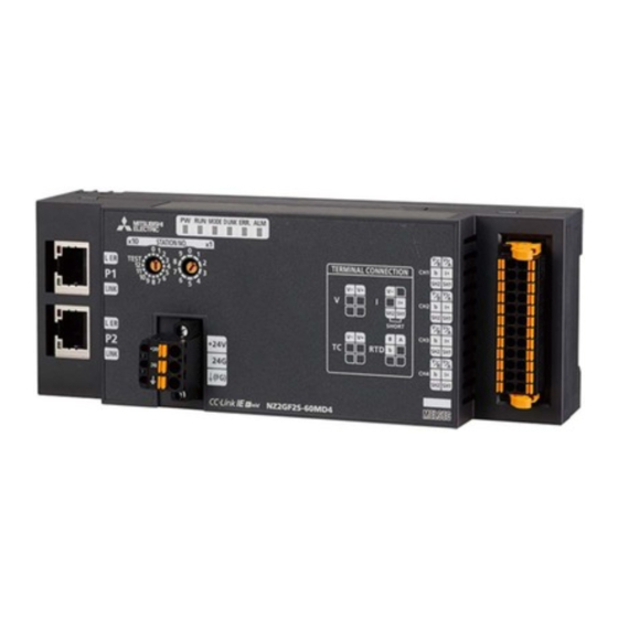
Page 14: Chapter 1 Part Names
PART NAMES Name Application Station number setting switch A rotary switch for the following setting and test. • Station number setting (Page 30 Switch Setting) • Unit Test (Page 103 Unit Test) When operating the station number setting switch, use a flathead screwdriver with 3.5mm or less width of the tip. - Page 15 Multiple input module status and LED status The following table lists the correspondence between the multiple input module status and the LED status. Multiple input module Data link status LED status status PW LED RUN LED MODE D LINK ERR. LED ALM LED Normal mode Disconnected...
-
Page 16: Chapter 2 Specifications
SPECIFICATIONS This chapter describes the specifications of the multiple input module. General Specifications Item Specifications Operating ambient 0 to 55 temperature Storage ambient -25 to 75 temperature Operating ambient 5 to 95%RH, non-condensing humidity Storage ambient humidity Vibration resistance Compliant with JIS Frequency Constant... -
Page 17: Performance Specifications
Performance Specifications Item NZ2GF2S-60MD4 Station type Remote device station Number of analog input channels 4 channels/1 module (isolation between channels) Analog input Voltage -10 to 10VDC (input resistance 1M) Current 0 to 20mADC (input resistance 250) Micro voltage -100 to 100mVDC (input resistance 1M) - Page 18 Item NZ2GF2S-60MD4 Isolation resistance • Between power supply/communication system batch and analog input: 500VDC 10M or higher • Between analog input channels: 500VDC 10M or higher Noise immunity Noise voltage 500Vp-p, noise width 1s, noise frequency 25 to 60Hz (noise simulator...
-
Page 19: Function List
Function List The following table lists the functions of the multiple input module. V: Voltage, I: Current, mV: Micro voltage, TC: Thermocouple, RTD: Resistance temperature detector : Available, : Not available Item Description Input type Reference ... - Page 20 Item Description Input type Reference iQ Sensor iQ Sensor Solution data backup/restoration This function allows data such as the setting data function of the slave station to be backed up in the SD Solution memory card of the CPU module of the master Reference station.
-
Page 21: List Of Remote I/O Signals
List of Remote I/O Signals This section lists I/O signals for a master/local module. The assignment of I/O signals shown is an example with the remote I/O signals of the multiple input module assigned to RX0 to RX1F and RY0 to RY1F. Remote input (RX) indicates the input signal from the multiple input module to the master/local module. -
Page 22: Remote Register List
Remote Register List This section lists remote register areas for a master/local module. The assignment of the remote register areas shown is an example with the remote register areas of the multiple input module assigned to RWr0 to RWr17 and RWw0 to RWw17. Remote register (RWr) is the information input from the multiple input module to the master/local module. -
Page 23: List Of Remote Buffer Memory Areas
List of Remote Buffer Memory Areas This section lists the remote buffer memory areas of the multiple input module. Range of remote buffer memory addresses The following table lists the ranges of remote buffer memory addresses occupied by multiple input modules. For details on the remote buffer memory, refer to the following. - Page 24 Parameter area (address: 0000H to 01FFH) For the parameter area, parameters can be set by means of the CC IE Field configuration of the engineering tool, or the REMTO instruction. The parameters in the parameter area are backed up to the non-volatile memory. Parameters backed up to the non-volatile memory are read in the parameter area when the module power supply is turned off and on or the module returns from remote reset.
- Page 25 Monitoring area (address: 0500H to 06FFH) ■Station-based monitor data Address Description Decimal Hexadecimal 1280 to 1535 0500H to System area 05FFH ■Module-based monitor data R: Readable through a program Address Description Default value Read/Write Decimal Hexadecimal 1536 0600H CH1 Input type/range monitor 0000H 1537 0601H...
- Page 26 Error history area (address: 0A00H to 0FFFH) ■Station-based error history data R: Readable through a program Address Description Default value Read/Write Decimal Hexadecimal 2560 0A00H Error history 1 Error code 0000H 2561 0A01H Order of generation 0000H 2562 0A02H [Error time] First two digits of the year/Last 0000H two digits of the year 2563...
- Page 27 Module control data area (address: 1000H to 11FFH) ■Station-based control data R: Readable through a program, W: Writable through a program Address Description Default value Read/Write Decimal Hexadecimal 4096 1000H Error history clear command 4097 1001H Error history clear completed 4098 1002H Parameter area initialization command...
-
Page 28: Chapter 3 Procedures Before Operation
PROCEDURES BEFORE OPERATION This chapter describes the procedures before operation. Station number setting Set the station number of the multiple input module with the station number setting switch. Page 30 Station number setting Mounting Mount the multiple input module on the DIN rail. Page 31 Installation Environment and Installation Position Page 33 Installation Wiring... - Page 29 MEMO 3 PROCEDURES BEFORE OPERATION...
-
Page 30: Chapter 4 System Configuration
SYSTEM CONFIGURATION This chapter describes the configuration of the system using a multiple input module. For CC-Link IE Field Network configuration, refer to the following manual. User's manual for the master/local module used Applicable System Applicable master station When using an multiple input module, use the following products as a master station. Model name First five digits of serial number RJ71GF11-T2... - Page 31 MEMO 4 SYSTEM CONFIGURATION 4.1 Applicable System...
-
Page 32: Chapter 5 Installation And Wiring
INSTALLATION AND WIRING This chapter describes the installation and wiring of the multiple input module. Switch Setting Station number setting Set the station number with the rotary switch on the front of the module. The setting value of the station number becomes valid when the module is powered on. -
Page 33: Installation Environment And Installation Position
Installation Environment and Installation Position Installation environment Installation location Do not install the multiple input module to the place where: • Ambient temperature is outside the range of 0 to 55; • Ambient humidity is outside the range of 5 to 95% RH; •... -
Page 34: Installation Direction
Installation direction The multiple input module can be installed in six directions. Use the DIN rail to install the module. Downward installation DIN rail Horizontal installation Vertical installation Horizontal installation (upside down) Upward installation 5 INSTALLATION AND WIRING 5.2 Installation Environment and Installation Position... -
Page 35: Installation
Installation Mounting the modules on a DIN rail An example of the use of the DIN rail stopper is described in the following procedure. Fix the module according to the manual of the DIN rail stopper used. Mounting procedure Hang the upper tabs of the module on a DIN rail. Push the module into position until the DIN rail hook of the module clicks. - Page 36 Hold the DIN rail stopper in the direction opposite to the arrow on the stopper and tighten the screw with a driver. Install the DIN rail stopper on the right side of the module in the same procedure. Pay attention to install the DIN rail stopper upside down for the right side.
- Page 37 Removal procedure Remove the DIN rail stoppers. Remove the stoppers from the DIN rail by reversing the above procedure. Press down the DIN rail hook using a flathead screwdriver and pull the bottom of the module to remove the module from the DIN rail. Applicable DIN rail model (compliant with IEC 60715) •...
-
Page 38: Wiring
Wiring Wiring with terminal block for module power supply and FG Tightening torque Tighten the terminal block mounting screws within the following specified tightening torque range. Tightening the screws too much may damage the module case. Screw type Tightening torque range Terminal block mounting screw (M2.5 screw) 0.2 to 0.3Nm Wire to be used... - Page 39 Connecting and disconnecting the cable To connect the cable, fully insert a wire having a bar solderless terminal into a wire insertion opening. After inserting the wire, pull it lightly to check that it is securely clamped. A continuity check can be conducted using a test terminal (1). To disconnect the cable, push in the open/close button using a flathead screwdriver.
- Page 40 List of the reference products of bar solderless terminals The following table lists the reference products of bar solderless terminals. Product name Model name Applicable wire size Bar solderless terminal Contact tool Bar solderless TE 0.5-8, TE 0.5-10 0.3 to 0.5 NH79 NICHIFU Co., Ltd.
-
Page 41: Wiring Of Ethernet Cable
Wiring of Ethernet cable Connecting the Ethernet cable ■Connecting Power off the power supplies of the multiple input module and the external device. Push the Ethernet cable connector into the multiple input module until it clicks. Pay attention to the connector's direction. - Page 42 ■Disconnecting Power off the module. Press the latch down and unplug the Ethernet cable. Precautions ■Laying Ethernet cables • Place the Ethernet cable in a duct or clamp them. If not, dangling cable may swing or inadvertently be pulled, resulting in damage to the module or cables or malfunction due to poor contact.
-
Page 43: Wiring For Analog Input Terminal Block
Wiring for analog input terminal block Wire to be used The following table describes the wire to be connected to the analog input terminal block. Diameter Type Material Temperature rating 24 to 16 AWG Stranded wire Copper wire 75 or higher Installing and removing the terminal block The following procedures show how to install and remove the terminal block. - Page 44 ■Installation procedure Move the lever to the locking lever position and push the terminal block. If the terminal block is fully pushed in, the hook of the lever hangs on the module and fits the terminal block. The terminal block can be inserted with the lever locations other than the lock lever position. After insertion, confirm that the lever is in the lock lever position.
- Page 45 List of the reference products of bar solderless terminals The following table lists the reference products of bar solderless terminals. Product name Model name Applicable wire size Bar solderless terminal Contact tool Bar solderless TE 0.5-10 0.3 to 0.5 NH79 NICHIFU Co., Ltd.
- Page 46 Wiring to the terminal block The following figures show wiring to the terminal block. The wiring to the terminal block can be also checked by the "TERMINAL CONNECTION" on the front surface of the multiple input module. V: At current input and micro voltage input I: At current input TC: At thermocouple input RTD: At resistance temperature detector input...
- Page 47 ■Current input Always connect SH1 and SH2. Terminal connection diagram (TERMINAL CONNECTION) Wiring V-/B V+/A V-/B V+/A V-/B V+/A V-/B V+/A 5 INSTALLATION AND WIRING 5.4 Wiring...
- Page 48 ■Thermocouple input Terminal connection diagram (TERMINAL CONNECTION) Wiring V-/B V+/A V-/B V+/A V-/B V+/A V-/B V+/A 5 INSTALLATION AND WIRING 5.4 Wiring...
- Page 49 ■Resistance temperature detector input Terminal connection diagram (TERMINAL CONNECTION) Wiring V-/B V+/A V-/B V+/A V-/B V+/A V-/B V+/A Precautions As one of the conditions to ensure the functions of the multiple input module and maintain a high reliability system, external wiring which is not easily affected by noise is required.
-
Page 50: Wiring Examples With An External Device
Wiring examples with an external device The following figures show the external wiring. If the circuit between the terminals of unused channels is kept open and the conversion is enabled, an undefined digital value may be output. To avoid this phenomenon, set CH Input type/range setting (address: 0100H to 0103H) of the unused channels to Conversion disable (0H). - Page 51 ■Micro voltage input Signal source: -100 to 100mV V+/A Filter circuit conversion 250Ω V-/B *1 For the wire, use the 2-core shielded twisted pair cable. *2 Always ground the shield wire of the wire in each channel. ■Thermocouple input V+/A Filter circuit conversion 250Ω...
-
Page 52: Chapter 6 Various Settings
VARIOUS SETTINGS This chapter describes the setting procedures of the multiple input module. This chapter uses GX Works2 for explanations. Parameter Setting Set the parameter of this module with the network parameter written to the CPU module of the master station. For the setting procedure of the master station, refer to the following manual. - Page 53 Operating procedure Open the CC IE Field configuration window. For the master/local module QJ71GF11-T2 Project window [Parameter] [Network Parameter] [Ethernet / CC IE / MELSECNET] [CC IE Field Configuration Setting] button Select the multiple input module in "List of stations" (1) on the CC IE Field configuration window. Open the "Parameter Processing of Slave Station"...
- Page 54 Double-click the item to change the setting, and input the setting value. Setting item Reference Page 59 Input Type/Range Setting Input type/range setting CH1 Input type/range setting CH2 Input type/range setting CH3 Input type/range setting CH4 Input type/range setting Page 61 Conversion Method Averaging process setting CH1 Averaging process setting CH1 Time average/Count average/Moving average...
- Page 55 Setting item Reference Page 64 Disconnection Detection Function Disconnection detection function CH1 Conversion setting for disconnection detection CH1 Conversion setting value for disconnection detection CH2 Conversion setting for disconnection detection CH2 Conversion setting value for disconnection detection CH3 Conversion setting for disconnection detection CH3 Conversion setting value for disconnection detection...
-
Page 56: Changing The Parameter
Changing the Parameter This section describes the procedure for changing the parameter. The precautions for changing the parameter are the same as those in the following section. Page 50 Precautions Changing the network configuration When changing the network configuration diverting the created project, set the parameter in the following procedure. Power off the module power supply. - Page 57 Click the [Refresh Parameters] button to display the refresh parameter setting window. Set the refresh parameter. Change the value as necessary. Write the set parameter to the CPU module of the master station and reset the CPU module. Change the status of the CPU module of the master station to RUN. The network configuration setting is now completed.
-
Page 58: Changing The Parameter Without Changing The Network Configuration
Changing the parameter without changing the network configuration To change only the created module parameter of the slave station without changing the network configuration, set the parameter in the following procedure. Open the CC IE Field configuration window. For the master/local module QJ71GF11-T2 Project window ... - Page 59 Set "Method selection" to "Parameter write". Set "Write Value". The procedures are as follows. • Click the title cell of "Read Value" to select all the items and copy them. • Click the title cell of "Write Value" to select all the items and paste the copy. •...
-
Page 60: Chapter 7 Functions
FUNCTIONS This chapter describes the functions of the multiple input module and the setting procedures for those functions. For details on remote I/O signals, remote register, and remote buffer memory, refer to the following. Page 106 Details of Remote I/O Signals Page 114 Details of Remote Register Page 117 Details of Remote Buffer Memory Areas Processing Order of Each Function... -
Page 61: Input Type/Range Setting
Input Type/Range Setting The input type and input range that are to be used can be selected for each channel. Setting procedure Set "Method selection" to "Parameter write". CC IE Field configuration window Select a multiple input module in "List of stations". [CC IE Field Configuration] [Online] ... - Page 62 Conversion enable and conversion disable Whether to enable or disable conversion for each channel can be set in "CH Input type/range setting". In this manual, conversion enable and conversion disable are defined as follows. ■Conversion disable Indicates the state generated by selecting "0: Conversion disable" in "CH Input type/range setting". In this case, the conversion is not performed in the target channel.
-
Page 63: Conversion Method
Conversion Method Set sampling processing or averaging processing for each channel. Sampling processing Analog input values and temperature input values are converted at every conversion cycle and stored in the remote register as digital output values. Processing does not depend on the number of conversion enabled channels and the conversion cycle of sampling processing is fixed at 40ms. - Page 64 ■Moving average The average of a specified number of digital output values that are imported at every conversion cycle is calculated and stored in the remote register. Because the target range for averaging processing is moved in response to every conversion cycle, the latest digital output value can be always obtained.
- Page 65 Setting procedure ■Sampling processing Set "Method selection" to "Parameter write". CC IE Field configuration window Select a multiple input module in "List of stations". [CC IE Field Configuration] [Online] [Parameter Processing of Slave Station] Set "CH Averaging process setting" to "0: Sampling processing". ■Averaging processing Set "Method selection"...
-
Page 66: Disconnection Detection Function
Disconnection Detection Function This function outputs an alarm at disconnection detection of the external wiring (resistance temperature detector, thermocouple, conducting wire, or auxiliary conducting wire), provided that the input type is a micro voltage, thermocouple, or resistance temperature detector. Notification •... - Page 67 Conversion setting for disconnection detection Conversion setting for disconnection detection (address: 010FH) can configure the values stored in CH Digital output value (RWr2 to RWr5) and CH Digital output value (32 bits) (RWr10 to RWr17) upon disconnection detection. Thus, disconnection detection is enabled only by checking CH...
- Page 68 • Resistance temperature detector Input range Temperature measured value () Temperature measuring range Up scale Down scale Pt100 (0 to 200) 0 to 200 210.0 -10.0 Pt100 (-20 to 120) -20 to 120 127.0 -27.0 Pt100 (-200 to 850) -200 to 850 902.5 -252.5 JPt100 (0 to 200)
- Page 69 ■When the setting is Disable (1H) When Error clear request flag (RYA) is turned on and off after the recovery of the disconnection, the status changes as follows. • Disconnection detection flag (RWrD) turns off. • Disconnection detection signal (RX1B) turns off. •...
-
Page 70: Cold Junction Temperature Compensation Setting Function
Cold Junction Temperature Compensation Setting Function By selecting the setting with or without cold junction compensation using the built-in temperature sensor in the multiple input module, two types of cold junction compensation including a temperature sensor and external (ice bath) can be conducted. Operation The operations when cold junction compensation is performed using the built-in temperature sensor in the multiple input module and when cold junction compensation is performed outside the module are described below. - Page 71 Setting procedure Set "Method selection" to "Parameter write". CC IE Field configuration window Select a multiple input module in "List of stations". [CC IE Field Configuration] [Online] [Parameter Processing of Slave Station] Set "Cold contact compensation setting" to either "0: With cold junction temperature compensation" or "1: Without cold junction temperature compensation".
-
Page 72: Input Signal Error Detection Function
Input Signal Error Detection Function This function outputs an alarm if an analog input value exceeds a preset range, provided that the input type is voltage or current. Detection range Out of detection range Analog input value Included CH1 Analog input value Normal input value Error... - Page 73 Detection method One of the following detection methods can be selected. Detection method Detection condition Disable (0H) Input signal error detection is not performed. Upper and lower limit detection (1H) When the analog input value becomes equal to or greater than the input signal error detection upper Error detection limit value, or becomes equal to or smaller than the input signal error detection lower limit value, an...
- Page 74 ■Simple disconnection detection Simple disconnection detection is enabled when current (4 to 20mA) (0010H) or voltage (1 to 5V) (0020H) is set in CH Input type/range setting (address: 0100H to 0103H). When an analog input value satisfies the following conditions, the module determines a disconnection and turns on the corresponding bit of Disconnection detection flag (RWrD).
- Page 75 Clearing input signal errors The method for clearing input signal errors differs depending on the setting of Input signal error/disconnection detection automatic clear enable/disable setting (address: 0109H). ■When the setting is Enable (0H) Once the analog input value is adjusted to fall within the setting range, the status will be automatically changed as follows. •...
- Page 76 ■Input signal error detection lower limit value This value is calculated by subtracting "the value after multiplying the analog input range width (gain value - offset value) by Input signal error detection lower limit setting value (%)" from the lower limit value of each range. Only the value below the lower limit value of the range can be set.
- Page 77 Setting procedure Set "Method selection" to "Parameter write". CC IE Field configuration window Select a multiple input module in "List of stations". [CC IE Field Configuration] [Online] [Parameter Processing of Slave Station] Set "Input signal error/disconnection detection auto clear enable/disable setting" to either "0: Enable" or "1: Disable". Setting item Setting range Input signal error/disconnection detection auto clear enable/disable setting...
- Page 78 Setting example of input signal error detection The following example shows the case when detecting an input signal error under the condition that the analog input value is below 2.4mA or beyond 21.6mA for the channel set as follows. Item Setting value Input range 4 to 20mA...
-
Page 79: Error Notification Function
Error Notification Function When an error, warning, or alarm occurs, the occurrence of the error, warning, or alarm is notified to the master station using remote input signals and remote register. Notification of the error, warning, or alarm can be checked by the LEDs on the front of the multiple input module. - Page 80 Notification of a warning or alarm The occurrence of a warning or alarm is notified to the master station via the following method. Item Description Reference Warning flag (RX7) Turns on when a minor error occurs. Page 106 Warning flag Latest warning code (RWr1) The error code or alarm code is stored when a Page 95 List of Error Codes...
- Page 81 Method for clearing an error by executing the command of the slave station The following describes how to clear an error by executing the command of the slave station. Select the multiple input module in "List of stations" (1) on the CC IE Field configuration window. Open the "Command Execution of Slave Station"...
-
Page 82: Cc-Link Ie Field Network Diagnostic Function
CC-Link IE Field Network Diagnostic Function This function allows the presence or absence of a network error to be checked by accessing the engineering tool connected to the CPU module. How to use The following instructions assume the use of GX Works2 as the engineering tool. Connect GX Works2 to the CPU module. - Page 83 Some of items cannot be diagnosed depending on the master/local module or the simple motion module used. For details, refer to the user's manual for the master/local module or simple motion module used. User's manual for the master/local module used Remote operation Select a slave station to be reset and click the [Remote Operation] button.
-
Page 84: Chapter 8 Programming
PROGRAMMING This chapter describes the programming of the multiple input module. Precautions for Programming This section describes precautions to create CC-Link IE Field Network programs. Cyclic transmission program For a cyclic transmission program, interlock with the following link special relay (SB) and link special register (SW). •... -
Page 85: Programming Procedure
• For the master/local module: QJ71GF11-T2 (start I/O number: 0000H to 001FH) • Input module: QX40 (start I/O number: 0020H to 002FH) (2)Remote device station (station No.1) • Multiple input module (NZ2GF2S-60MD4) The setting procedure assumes the use of GX Works2 as the engineering tool. ■Assignment of link devices... - Page 86 Programming condition Configure the settings for CH1 to CH4 to enable conversion and read the digital output values. The following table lists the other programming conditions. Item Description Input type/range setting Voltage (1 to 5V) Current (4 to 20mA) Resistance temperature Thermocouple (type R detector (Pt100 (-200 to thermocouple (-50 to 1760)
- Page 87 Device for user Device Description Digital output value read command QX10 (X20 to X2F) Error reset command X1007 Warning flag Multiple input module (RX0 to RX1F) X1009 Initial data setting completion flag X100A Error flag X100B Remote READY X1010 CH1 Conversion completed flag X1011 CH2 Conversion completed flag X1012...
- Page 88 Setting procedure Connect GX Works2 to the master station to configure the setting. Create a project on GX Works2. Select "QCPU (Q mode)" for "Series" and select "Q10UDH" for "Type". [Project] [New] Display the network parameter setting window and configure the setting as follows. Project window ...
- Page 89 Display the CC IE Field configuration window and configure the configuration and station number of the slave station as follows. [CC IE Field Configuration Setting] button Close the CC IE Field configuration window. [CC IE Field Configuration] [Close with Reflecting the Setting] Display the refresh parameter setting window and configure the setting as follows.
- Page 90 Write the set parameter to the CPU module of the master station and reset the CPU module, or turn off and on the power supply. [Online] [Write to PLC] Display the "Parameter Processing of Slave Station" window. Project window [Parameter] [Network Parameter] [Ethernet / CC IE / MELSECNET] [CC IE Field Configuration Setting] button ...
- Page 91 Program example Create the following program with GX Works2. Read CH1 Digital output value. Read CH2 Digital output value. Read CH3 Digital output value (32 bits). Read CH4 Digital output value. Read Input signal error detection flag. Read Disconnection detection flag. Processing when an input signal error (upper limit) has occurred in CH1.
-
Page 92: Chapter 9 Maintenance And Inspection
MAINTENANCE AND INSPECTION The multiple input module has no special item to be inspected. However, to maintain the best condition of the system, perform the inspection in accordance with the items described in the user's manual of the CPU module used. 9 MAINTENANCE AND INSPECTION... - Page 93 MEMO 9 MAINTENANCE AND INSPECTION...
-
Page 94: Chapter 10 Troubleshooting
TROUBLESHOOTING This chapter describes error contents that may occur while the multiple input module is used and those troubleshooting. This chapter uses GX Works2 for explanations. 10.1 Checking for the Error Codes and the Alarm Codes Error codes can be checked by any of the following methods: Page 92 Checking by executing a command of the slave station Page 94 Checking by Latest error code (RWr0) Warning codes and alarm codes can be checked by any of the following methods:... - Page 95 If the following window is displayed, click the [Yes] button. If the following window is displayed, click the [OK] button. The error history of the multiple input module is displayed in "Execution Result". Item Storage content Error and Solution The action for the error that occurred is displayed. Order of generation The order of error occurrence is displayed.
- Page 96 • The error history registers 15 errors at a maximum. If 16 or more errors occur, errors are deleted from the oldest. • If the same error occurs continuously, only the error that occurred first is stored to the error history. •...
-
Page 97: List Of Error Codes
10.2 List of Error Codes This section describes error codes. Error codes are classified by error number as follows. Error code and alarm code Classification Reference 0000H to 0FFFH, D52BH Multiple input module error Page 95 List of error codes (0000H to 0FFFH, D52BH) D000H to DFFFH (excluding D52BH) CC-Link IE Field Network error... - Page 98 Error code Classification Error name Description and cause Action (hexadecimal) 030H Moderate error Out of the count average The count average setting value set in Set the count average setting value within the setting range CH Time Average/Count Average/ range of 4 to 62500 times. Moving Average (address: 0105H to 0108H) is out of the range of 4 to 62500 times.
- Page 99 When multiple errors or alarms occur, only the latest error code or alarm code is stored in Latest error code (RWr0) or Latest warning code (RWr1). The errors or alarms that have occurred in the past can be checked in the error history of the engineering tool. For the error history, refer to the following.
- Page 100 ■Communication system error in which the D LINK LED does not change When this error occurs, the ERR. LED does not turn on. The D LINK LED also remains turned on. Because this error is automatically resolved after occurring, CC-Link IE Field Network diagnostics cannot troubleshoot this error.
-
Page 101: List Of Alarm Codes
10.3 List of Alarm Codes The following table lists the alarm codes. Alarm code Classification Alarm name Description and cause Action (hexadecimal) • In the event that Input signal error/ 0BH Minor error Input signal error An input signal error has occurred. detection ... -
Page 102: Checking By The Leds
10.4 Checking by the LEDs This section describes how to troubleshoot the system by the LEDs. When the PW LED does not turn on Check item Action Is any LED other than the PW LED turned on? When any LED other than the PW LED turns on, the possible cause is a hardware failure. - Page 103 When the D LINK LED flashes Check item Action Does the station number setting of the multiple input module match the station Match the station number of the multiple input module with the station number number of the multiple input module specified in the network configuration specified in the network configuration settings of the master station or in the settings of the master station or in the CC IE Field configuration? CC IE Field configuration.
- Page 104 When the ERR. LED turns on Check item Action Has any error occurred? Identify the error factor of the multiple input module with the engineering tool to take the corrective action. Page 92 Checking for the Error Codes and the Alarm Codes When the ALM LED flashes Check item Action...
-
Page 105: Unit Test
10.5 Unit Test A unit test will check if there is any error in the hardware of the multiple input module. Operating procedure Power off the multiple input module. Connect the PORT1 and PORT2 connectors of the multiple input module with an Ethernet cable. Set the station number setting switch as follows. -
Page 106: Troubleshooting For Each Phenomenon
10.6 Troubleshooting for Each Phenomenon This section describes troubleshooting for each phenomenon. Perform troubleshooting for each phenomenon when the multiple input module does not operate properly with no error. If an error occurs in the multiple input module, identify the cause of the error using the engineering tool. When a digital output value cannot be read Check item Action... - Page 107 When a digital output value does not fall within the range of accuracy Check item Action Is any measure to reduce noise taken? Take measures to reduce noise, such as using a shield wire for connection. When the input type is thermocouple Has the thermocouple input been Always use shielded compensation lead wires for the connection and ground affected by noise?
-
Page 108: Appendices
APPENDICES Appendix 1 Details of Remote I/O Signals This section describes the details of the remote I/O signals assigned to the master/local module. The assignment of each device number is for the case when the remote I/O signals of the multiple input module are assigned as follows. - Page 109 Initial data setting completion flag ■Device number Name Device number Initial data setting completion flag ■Description Regarding Initial data setting completion flag (RX9), turn on Initial data setting request flag (RY9) after writing parameter data to the remote buffer memory by the REMTO instruction. Once the change in operating conditions is completed, Initial data setting completion flag (RX9) turns on.
- Page 110 Error flag ■Device number Name Device number Error flag ■Description Error flag (RXA) turns on when a moderate error or major error occurs. To clear Latest error code (RWr0), turn on and off Error clear request flag (RYA). ■When a moderate error occurs Controlled by the multiple input module Controlled by the program Latest error code (RWr0)
- Page 111 Remote READY ■Device number Name Device number Remote READY ■Description Remote READY (RXB) turns on after the module power supply is powered on. This Remote READY is used as an interlock condition when the master station reads/writes data from/to the remote register and remote buffer memory areas of the multiple input module.
- Page 112 ■OFF state of Disconnection detection signal (RX1B) The OFF state of Disconnection detection signal (RX1B) depends on the setting of Input signal error/disconnection detection automatic clear enable/disable setting (address: 0109H). • When the setting is Enable (0H) Disconnection detection signal (RX1B) turns off when the disconnection is recovered and all Disconnection detection flags (RWrD) are turned off.
- Page 113 Input signal error detection signal ■Device number Name Device number Input signal error detection signal RX1C ■Description Input signal error detection signal (RX1C) turns on when a detection condition is set in Input signal error detection setting (address: 010AH) and an analog input value exceeds the range set in CH Input signal error detection setting value (address: 010BH to 010EH) in any of the channels in which conversion is enabled.
- Page 114 • When the setting is Disable (1H) When Error clear request flag (RYA) is turned on and off after the analog input value is adjusted to fall within the setting range, Input signal error detection signal (RX1C) turns off. Controlled by the multiple input module Controlled by the program State Input signal error detection flag...
-
Page 115: Remote Output Signal
Remote output signal Initial data setting request flag ■Device number Name Device number Initial data setting request flag ■Description Turn on Initial data setting request flag (RY9) after writing parameter data to the remote buffer memory in the program. Once the change in operating conditions is completed, Initial data setting completion flag (RX9) turns on. For the timing of turning the flag on and off, refer to the following. -
Page 116: Appendix 2 Details Of Remote Register
Appendix 2 Details of Remote Register This section describes the details of remote register areas assigned to the master/local module. The assignment of each device number is for the case when the remote register areas of the multiple input module are assigned as follows. - Page 117 Input signal error detection flag ■Device number Name Device number Input signal error detection flag RWrA ■Description Input signal error detection flag (RWrA) enables us to check the input signal status of each channel. Lower Upper Lower Upper Lower Upper Lower Upper limit...
- Page 118 Digital output value (32 bits) ■Device number Name Device number CH Digital output value (32 bits) RWr10, RWr11 RWr12, RWr13 RWr14, RWr15 RWr16, RWr17 ■Description For CH Digital output value (32 bits) (RWr10 to RWr17), the converted digital output value is stored in 32-bit signed binary format.
-
Page 119: Appendix 3 Details Of Remote Buffer Memory Areas
Appendix 3 Details of Remote Buffer Memory Areas This section describes the details of remote buffer memory areas of the multiple input module. Input type/range setting ■Address Name Address CH Input type/range setting 0100H 0101H 0102H 0103H ■Description CH Input type/range setting (address: 0100H to 0103H) configures the settings of the input type and input range for each channel. - Page 120 ■Enabling the setting details Turn on and off Initial data setting request flag (RY9) to enable the setting details. Averaging process setting ■Address Name Address Averaging process setting 0104H ■Description Averaging process setting (address: 0104H) is set when selecting sampling processing or averaging processing for each channel.
- Page 121 ■Input type Available: , Not available: Voltage Current Micro voltage Thermocouple Resistance temperature detector ■Enabling the setting details Turn on and off Initial data setting request flag (RY9) to enable the setting details. Input signal error/disconnection detection automatic clear enable/disable setting ■Address Name Address...
- Page 122 • When a value out of the above setting range is set, Out of the input signal error detection setting range (error code: 081H) is stored in Latest error code (RWr0). • Simple disconnection detection (4H) is enabled only when current (4 to 20mA) (0010H) or voltage (1 to 5V) (0020H) is set in CH...
- Page 123 Conversion setting for disconnection detection ■Address Name Address Conversion setting for disconnection detection 010FH ■Description Conversion setting for disconnection detection (address: 010FH) configures the setting of the stored value to CH Digital output value (RWr2 to RWr5) and CH Digital output value (32 bits) (RWr10 to RWr17) upon disconnection detection for each channel.
- Page 124 ■Setting range The setting range is between -2147483648 and 2147483647. (Default value: 0) When the input type is set to the thermocouple or resistance temperature detector, set CH Conversion setting value for disconnection detection (address: 0110H to 0117H) as follows. •...
- Page 125 Error history ■Address Name Address 1 to 15 CH Error history 0A00H to 0AEF ■Description Error history (address: 0A00H to 0AEFH) records up to 15 errors generated in the module. Error history 2 (address: 0A10H to 0A1FH) to Error history 15 (address: 0AE0H to 0AEFH) store data in the same format as that of Error history 1 (address: 0A00H to 0A0FH).
- Page 126 ■Storage order of the error history The latest error is stored in Error history 1 (address: 0A00H to 0A0FH). For Error history 2 (address: 0A10H to 0A1FH) to Error history 15 (address: 0AE0H to 0AEFH), errors that occurred in the past are stored in reverse chronological order.
- Page 127 Parameter area initialization command ■Address Name Address Parameter area initialization command 1002H ■Description Parameter area initialization command (address: 1002H) sets the parameters stored in a remote buffer memory and non- volatile memory to the default value. When Non-volatile memory data error (parameter) (error code: 0130H) occurs, the module can be recovered using this command.
- Page 128 Parameter area initialization completed ■Address Name Address Parameter area initialization completed 1003H Parameter area initialization completed (address: 1003H) shows whether initialization of the parameters stored in a non- volatile memory has completed or not. (1) 0: Not performed, 1: Completed ■Operation of the parameter area initialization When setting the parameters stored in a non-volatile memory to the default values has completed, Parameter area initialization completed (address: 1003H) becomes Completed (1).
-
Page 129: Appendix 4 I/O Conversion Characteristic
Appendix 4 I/O Conversion Characteristic The I/O conversion characteristic of voltage or current is the slope of the line that joins the offset value and gain value, both of which are used when an analog signal (voltage or current) from outside the programmable controller is converted to the corresponding digital output value. - Page 130 Current input characteristic The following figure and tables show the analog input range list at current input and a graph of the current input characteristics. digit 32767 32000 -768 -32000 -32768 digit: Digital output value mA: Analog input current [mA] (a) Practical analog input range Input range setting Offset value...
- Page 131 Micro voltage input characteristic The following figure and tables show the analog input range list at micro voltage input and a graph of the micro voltage input characteristics. digit 32767 32000 -32000 -32768 -200 -100 digit: Digital output value mV: Analog input voltage [mV] (a) Practical analog input range Input range setting Offset value...
-
Page 132: Appendix 5 Accuracy
Appendix 5 Accuracy The accuracy of the multiple input module is the accuracy of the maximum digital output value. The following graph shows the fluctuation range of accuracy when the range of -10 to 10V is selected. digit 32000 -32000 digit: Digital output value V: Analog input value (V) (1) Fluctuation range... - Page 133 Measured temperature range accuracy at thermocouple input The calculation method of the accuracy when a thermocouple is connected is shown below. Accuracy () = (Conversion accuracy) + (Cold junction compensation accuracy) + (Allowable difference of thermocouple used) In the event of application under the following conditions •...
- Page 134 Type of thermocouple Measured temperature Conversion accuracy Maximum temperature Influence by 1 wiring range (at operating ambient error at ambient resistance (/) temperature 255) temperature 55 within the range from 0 to 55 Type U thermocouple -200 to -150 3.4 3.4...
- Page 135 ■Allowable difference of type T thermocouple Measured temperature Class Allowable difference 0.5 Between -40 and 125 (125 not included) Class 1 0.4% of the measured temperature Between 125 and 350 (350 not included) 1.0 Between -40 and 133 (133 not included) Class 2 0.75% of the measured temperature Between 133...
- Page 136 Measured temperature range accuracy at input of a resistance temperature detector The calculation method of the accuracy when a resistance temperature detector is connected is shown below. Accuracy () = (Conversion accuracy) + (Allowable difference of resistance temperature detector used) In the event of application under the following conditions •...
- Page 137 Accuracy of difference in conductor resistance values upon connection of RTD Constant current source V+/A Filter circuit conversion 250Ω V-/B • Install a resistance temperature detector so as to shorten the wiring length (minimize the conductor resistance values of RA, RB, and Rb) and set each conductor resistance value of RA, RB, and Rb to 150 or less. An accuracy error occurs with the following ratio by 1...
-
Page 138: Appendix 6 Processing Time Of Cc-Link Ie Field Network
Appendix 6 Processing Time of CC-Link IE Field Network The processing time of CC-Link IE Field Network is the time taken from reading analog input values in the multiple input module to storage of the data in the device of the CPU module of the master station. The processing time of CC-Link IE Field Network is determined in accordance with the following processing times. -
Page 139: Appendix 7 Emc And Low Voltage Directives
Appendix 7 EMC and Low Voltage Directives In each country, laws and regulations concerning electromagnetic compatibility (EMC) and electrical safety are enacted. For the products sold in the European countries, compliance with the EU's EMC Directive has been a legal obligation as EMC regulation since 1996, as well as the EU's Low Voltage Directive as electrical safety regulation since 1997. - Page 140 EMC Directive related standards ■Emission requirements Specifications Test item Test details Standard value EN61131-2: 2007 CISPR16-2-3 Radio waves from the product are • 30M to 230MHz, QP: 40dBV/m (10m in measurement Radiated emission measured. range) • 230M to 1000MHz, QP: 47dBV/m (10m in measurement range) CISPR16-2-1, Noise from the product to the power...
- Page 141 Installation in a control panel The module is an open-type device and must be installed inside a control panel. This ensures safety as well as effective shielding of module-generated electromagnetic noise. ■Control panel • Use a conductive control panel. • When securing the top or bottom plate using bolts, cover the grounding part on the control panel so that the part will not be painted.
- Page 142 Use shielded cables for external wiring and ground the shields of the external wiring cables to the control panel with the AD75CK cable clamp (manufactured by Mitsubishi Electric Corporation). (Ground the shield section 20 to 30cm away from the module.)
- Page 143 For the FG terminal on a multiple input module that is connected to the external power supply and CC-Link IE Field Network cables, attach a ferrite core 4cm apart from the module. (Ferrite core used for the tests conducted by Mitsubishi Electric Corporation: NEC TOKIN ESD-SR-250, TDK ZCAT3035- 1330) Example ■Noise filter (power supply line filter)
-
Page 144: Requirements To Compliance With The Low Voltage Directive
Requirements to compliance with the Low Voltage Directive The module operates at the rated voltage of 24VDC. The Low Voltage Directive is not applied to the modules that operate at the rated voltage of less than 50VAC and 75VDC. APPENDICES Appendix 7 EMC and Low Voltage Directives... -
Page 145: Appendix 8 How To Check The Serial Number And Function Version
Appendix 8 How to Check the Serial Number and Function Version The serial number and function version of the multiple input module can be checked on the rating plate. The serial number can be checked with "Production Information" of the CC-Link IE Field Network diagnostics as well. Checking on the rating plate MODEL PASSED... - Page 146 The production information is displayed. The serial number on the rating plate is displayed in "Production Information". APPENDICES Appendix 8 How to Check the Serial Number and Function Version...
-
Page 147: Appendix 9 External Dimensions
Appendix 9 External Dimensions The following figure shows the external dimensions of the multiple input module. 43.5 16.5 DIN rail center (Unit: mm) APPENDICES Appendix 9 External Dimensions... -
Page 148: Index
INDEX ....28 ... .129 Applicable master station Micro voltage input characteristic ....28 . - Page 149 MEMO...
-
Page 150: Revisions
Japanese manual number: SH-081681-C This manual confers no industrial property rights or any rights of any other kind, nor does it confer any patent licenses. Mitsubishi Electric Corporation cannot be held responsible for any problems involving industrial property rights which may occur as a result of using the contents noted in this manual. -
Page 151: Warranty
WARRANTY Please confirm the following product warranty details before using this product. 1. Gratis Warranty Term and Gratis Warranty Range If any faults or defects (hereinafter "Failure") found to be the responsibility of Mitsubishi occurs during use of the product within the gratis warranty term, the product shall be repaired at no cost via the sales representative or Mitsubishi Service Company. -
Page 152: Trademarks
TRADEMARKS The company names, system names and product names mentioned in this manual are either registered trademarks or trademarks of their respective companies. In some cases, trademark symbols such as ' ' or ' ' are not specified in this manual. SH(NA)-081682ENG-C... - Page 154 SH(NA)-081682ENG-C(2211)MEE MODEL: CCIEF-MD-U-E MODEL CODE: 13JX61 HEAD OFFICE : TOKYO BUILDING, 2-7-3 MARUNOUCHI, CHIYODA-KU, TOKYO 100-8310, JAPAN NAGOYA WORKS : 1-14 , YADA-MINAMI 5-CHOME , HIGASHI-KU, NAGOYA , JAPAN When exported from Japan, this manual does not require application to the Ministry of Economy, Trade and Industry for service transaction permission.
Need help?
Do you have a question about the NZ2GF2S-60MD4 and is the answer not in the manual?
Questions and answers