Table of Contents
Advertisement
Quick Links
Advertisement
Table of Contents
Troubleshooting

Subscribe to Our Youtube Channel
Related Manuals for Mitsubishi Electric AJ65SBT2B-64RD3


Summary of Contents for Mitsubishi Electric AJ65SBT2B-64RD3
- Page 1 RTD Input Module Type AJ65SBT2B-64RD3 User's Manual...
-
Page 3: Safety Precautions
SAFETY PRECAUTIONS (Read these precautions before using this product.) Before using this product, please read this manual and the relevant manuals introduced in this manual carefully and pay full attention to safety to handle the product correctly. The instructions given in this manual are concerned with this product. For the safety instructions of the programmable controller system, please read the CPU module user’s manual. - Page 4 [Installation Precautions] CAUTION Use the module in an environment that meets the general specifications given in this manual. Operating it in any other environment may cause an electric shock, fire, malfunction, product damage or deterioration. For protection of the switches, do not remove the cushioning material before installation. Securely fix the module with the DIN rail or fixing screws.
- Page 5 [Wiring Precautions] CAUTION Be sure to shut off all phases of the external power supply used by the system before installation or wiring. Failure to do so may cause a damage to the product and/or malfunctions. Always ground the FG terminal to the protective ground conductor. Failure to do so may result in malfunctions.
- Page 6 [Wiring Precautions] CAUTION Do not install the control cable(s) together with the communication cable(s). Doing so may cause malfunctions due to noise. When disconnecting the cables from the module, do not hold and pull the cable part. Disconnect the cables after loosening the screws in the portions connected to the module. Pulling the cable that is still connected to the module may damage the module and/or cable and cause malfunctions due to poor cable connection.
- Page 7 [Disposal Precautions] CAUTION When disposing of this product, treat it as industrial waste.
-
Page 8: Conditions Of Use For The Product
Notwithstanding the above restrictions, Mitsubishi Electric may in its sole discretion, authorize use of the PRODUCT in one or more of the Prohibited Applications, provided that the usage of the PRODUCT is limited only for the specific applications agreed to by Mitsubishi Electric and provided further that no special quality assurance or fail-safe, redundant or other safety features which exceed the general specifications of the PRODUCTs are required. -
Page 9: Revisions
This manual confers no industrial property rights or any rights of any other kind, nor does it confer any patent licenses. Mitsubishi Electric Corporation cannot be held responsible for any problems involving industrial property rights which may occur as a result of using the contents noted in this manual. -
Page 10: Table Of Contents
INTRODUCTION Thank you for purchasing the Mitsubishi Electric programmable controllers. Before using this product, please read this manual carefully to fully understand the functions and performance of the programmable controller to ensure correct use. CONTENTS SAFETY PRECAUTIONS ..........................A - 1 CONDITIONS OF USE FOR THE PRODUCT....................A - 6... - Page 11 CHAPTER4 PROCEDURES AND SETTINGS BEFORE OPERATION 4 - 1 to 4 - 5 Procedures before Operation ......................4 - 1 Handling Precautions........................4 - 2 Part Names............................4 - 4 4.3.1 Transmission speed auto-tracking function ................4 - 5 Station Number Setting........................4 - 6 Module Mounting Orientation......................
-
Page 12: About Manuals
ABOUT MANUALS The following manuals are also related to the product. Refer to the following table for ordering a manual. Related manuals Manual number Manual name (model code) CC-Link System Master/Local Module Type AJ61BT11/A1SJ61BT11 User's Manual IB-66721 Describes the system configuration, performance specifications, functions, handling, wiring, and troubleshooting (13J872) of the AJ61BT11 and A1SJ61BT11. -
Page 13: Generic Terms And Abbreviations
GENERIC TERMS AND ABBREVIATIONS Unless otherwise specified, the following generic terms and abbreviations are used in this manual to describe the AJ65SBT2B-64RD3 RTD input module. Generic term/ Description abbreviation GX Developer Product name of the software package for the MELSEC programmable controllers... -
Page 14: Packing List
PACKING LIST The following table shows the packing list of the AJ65SBT2B-64RD3 RTD input module. Product Quantity AJ65SBT2B-64RD3 RTD input module RTD Input Module User's Manual (Hardware) AJ65SBT2B-64RD3 - 12... - Page 15 Memo - 13...
-
Page 16: Chapter1 Overview
(a) The module has built-in terminating resistor of 110 , which eases wiring. (b) The transmission speed of the AJ65SBT2B-64RD3 needs not be set by the user. It is set automatically according to the transmission speed set in the master station. - Page 17 OVERVIEW (7) Maintenance is easy. Since 2-piece terminal block is used, the maintenance is easy. 1.1 Features...
-
Page 18: Chapter2 System Configuration
SYSTEM CONFIGURATION CHAPTER2 SYSTEM CONFIGURATION This chapter describes the system configuration for using the AJ65SBT2B-64RD3. Overall Configuration This section describes the overall configuration for using the AJ65SBT2B-64RD3. CC-Link system master/local module (local station) CC-Link system master/local module (master station) Terminating resistor... -
Page 19: Applicable System
SYSTEM CONFIGURATION Applicable System This section describes the applicable system. (1) Applicable master modules For available master modules, visit the CC-Link Partner Association (CLPA) website http://www.cc-link.org/ Remark Check the specifications of the master module before use. (2) Restrictions on using the CC-Link dedicated instructions (RLPA, RRPA) The CC-Link dedicated instructions (RLPA, RRPA) cannot be used depending on the programmable controller CPU and master module used. -
Page 20: Chapter3 Specifications
SPECIFICATIONS CHAPTER3 SPECIFICATIONS This chapter describes the specifications of the AJ65SBT2B-64RD3. General Specifications This section describes the general specifications of the AJ65SBT2B-64RD3. Table 3.1 General specifications Item Specifications Operating ambient temperature 0 to 55 Storage ambient temperature -20 to 75... -
Page 21: Performance Specifications
SPECIFICATIONS Performance Specifications This section describes the performance specifications of the AJ65SBT2B-64RD3. Table 3.2 Performance specifications Item AJ65SBT2B-64RD3 Measurement method 3-conductor type Measured temperature value 16-bit signed binary (-2000 to 8500) Applicable RTD Pt100 (JIS C 1604-1997, IEC 751 1983), JPt100 (JIS C 1604-1981), Ni100 (DIN 43760 1987) - Page 22 SPECIFICATIONS Table 3.2 Performance specifications Item AJ65SBT2B-64RD3 Applicable wire size 0.3 to 2.0mm RAV1.25-3 (IEC 60715 compliant) [Applicable wire size: 0.3 to 1.25mm Applicable solderless terminal V2-MS3, RAP2-3SL, TGV2-3N [Applicable wire size: 1.25 to 2.0mm M4 screw 0.7mm 16mm or more (Tightening torque range: 0.78 to 1.08N m) Module mounting screw The module can also be mounted to a DIN rail.
-
Page 23: Specifications For Connecting Rtd
(b) Connect an RTD so that the discrepancy of the conductor resistance values between 1) and 2) becomes 10 or less. (c) Connect an RTD to the AJ65SBT2B-64RD3 so that the resistance value per conductor becomes 100 or less. Figure 3.1 Specifications for connecting RTD 3.2.2... -
Page 24: Functions
SPECIFICATIONS Functions This section describes the functions of the AJ65SBT2B-64RD3. 3.3.1 Function list Table 3.5 lists the functions of the AJ65SBT2B-64RD3. Table 3.5 Function list of the AJ65SBT2B-64RD3 Item Description Reference Conversion enable/disable Sets the conversion enable/disable status for each channel. -
Page 25: Conversion Enable/Disable Specification
SPECIFICATIONS 3.3.2 Conversion enable/disable specification The AJ65SBT2B-64RD3 can set a conversion enable/disable status for each channel. (1) Setting method Conversion enable/disable status is set using CH Conversion enable flag (RYn0 to RYn3). Table 3.6 Conversion enable/disable specification Setting item Description Conversion enable flag Temperature of the target device can be measured. -
Page 26: Sampling Processing/Average Processing Specification
SPECIFICATIONS 3.3.3 Sampling processing/average processing specification The AJ65SBT2B-64RD3 can specify conversion system (sampling processing, count average, time average, or moving average) for each channel. Conversion system is specified using CH Averaging processing selection (RWwm to RWwm+3). Averaging processing selection (RWwm to RWwm+3) - Page 27 SPECIFICATIONS (1) Sampling processing Measured temperature values are stored in the remote register once every sampling period. Operation example Sampling period (= Number of conversion-enabled channels 40ms) Sampling period 10) 11) Remote register 1st storage Measured 2nd storage temperature value 3rd storage Time [ms] Data transition in remote register...
- Page 28 SPECIFICATIONS (3) Time average processing Measured temperature values measured every sampling period are averaged and the averaged value is stored in the remote register. The values in the remote register are updated once every period set by user. The number of processing times within the set period of time is calculated in the following formula.
- Page 29 SPECIFICATIONS (4) Moving average processing Measured temperature values which are measured every sampling period for four times (current value + values of the past three times) are averaged and the averaged value is stored in the remote register. The latest measured temperature value can be obtained since averaging processing is performed moving for each sampling period.
-
Page 30: Disconnection Detection
3.3.4 Disconnection detection This function detects the disconnection status of the connected RTD for each channel. The AJ65SBT2B-64RD3 performs the followings when disconnection is detected. • Turns on CH Disconnection detection flag (RXn4 to RXn7). • Stores up scale or down scale value in CH Measured temperature value (RWrn to RWrn+3) of the disconnected channel. - Page 31 SPECIFICATIONS (c) Up scale/down scale values shown below varies depending on the measurement range to be used. Measured temperature value when Measurement range disconnection is detected Up scale Down scale 902.5 -252.5 200 to 850 Pt100 127.0 -27.0 20 to 120 210.0 -10.0 0 to 200...
-
Page 32: Measured Temperature Value Storage
(-1234 is stored) 3.3.6 RTD type and measurement range specification The AJ65SBT2B-64RD3 can select the RTD type to be used and measurement range for each channel. Set the RTD type to be used and measurement range using CH Measurement range (RYn8 to RY(n+1)3). -
Page 33: Remote I/O Signals
This section describes the assignment and functions of the remote I/O signals. 3.4.1 List of remote I/O signals Remote input (RX) is an input signal from the AJ65SBT2B-64RD3 to the master module, and remote output (RY) is an output signal from the master module to the AJ65SBT2B- 64RD3. -
Page 34: Details Of The Remote I/O Signals
64RD3 will not be guaranteed. 3.4.2 Details of the remote I/O signals This section describes the functions of each remote I/O signal of the AJ65SBT2B-64RD3. (1) CH Conversion completion flag (RXn0 to RXn3) This flag turns on when converted measured temperature value of the conversion- enabled channel is stored into the remote register after power is supplied to the CC- Link system or the reset operation of the CPU module is performed. - Page 35 Use the flag for an interlock to prevent incorrect output during offset/gain setting. (7) Initial data processing request flag (RX(n+1)8) This flag turns on for the AJ65SBT2B-64RD3 to request the initial data setting after power-on. The flag turns off when the initial data processing is completed (Initial data processing completion flag (RY(n+1)8) turns on).
- Page 36 On: Enable ..Temperature of the target device is measured. OFF: Disable ... Temperature of the target device is not measured. Operation of the AJ65SBT2B-64RD3 according to the conversion status change is described below. • When the conversion status is changed from "Disable" to "Enable"...
- Page 37 SPECIFICATIONS (12)CH Measurement range (RYn8 to RY(n+1)3) The RTD type to be used and measured temperature range are set. For details, refer to Section 3.3.6. (13)Disconnection detection upper/lower limit selection flag (all channel batch-select) (RY(n+1)4) A value to be stored in CH Measured temperature value (RWrn to RWrn+3) when disconnection is detected is set.
-
Page 38: Remote Register
SPECIFICATIONS Remote Register The AJ65SBT2B-64RD3 has a remote resister for data communications with a master module. This section describes the assignment and data structure of the remote register. 3.5.1 Remote register list Table 3.9 shows the assignment of remote register. -
Page 39: Chapter4 Procedures And Settings Before Operation
PROCEDURES AND SETTINGS BEFORE OPERATION CHAPTER4 PROCEDURES AND SETTINGS BEFORE OPERATION Procedures before Operation This section describes the procedures for operating the AJ65SBT2B-64RD3. Start Module mounting Refer to Section 4.2 and Section 4.5. (Mount the AJ65SBT2B-64RD3 to the panel or DIN rail.) -
Page 40: Handling Precautions
PROCEDURES AND SETTINGS BEFORE OPERATION Handling Precautions This section describes the precautions for handling the AJ65SBT2B-64RD3. CAUTION Do not touch the terminals while the power is on. Doing so may cause malfunction. Take care to prevent foreign matter such as dust or wire chips from entering the module. - Page 41 When installing a DIN rail, tighten the screws at a pitch of 200mm or less. (4) When mounting the AJ65SBT2B-64RD3 to the DIN rail, hold the center of the module and press it until the DIN rail hook at the bottom of the module clicks.
-
Page 42: Part Names
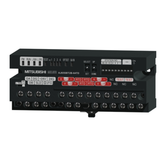
PROCEDURES AND SETTINGS BEFORE OPERATION Part Names This section describes each part name of the AJ65SBT2B-64RD3. Figure 4.3 Appearance of the AJ65SBT2B-64RD3 Table 4.2 Part names Name Description On: Power supply on PW LED Off: Power supply off On: Normal operation Flashing: 0.1s intervals: CH... -
Page 43: Transmission Speed Auto-Tracking Function
Used to mount the module to the DIN rail. L TER. (Line Turned on to enable the terminating resistor built in the AS65SBT2B-64RD3. Termination) Used when the AJ65SBT2B-64RD3 is connected at the end of the network. switch 4.3.1 Transmission speed auto-tracking function Transmission speed is set automatically according to the setting in the master module. -
Page 44: Station Number Setting
For details, refer to the user's manual of the master module used. Module Mounting Orientation The AJ65SBT2B-64RD3 can be mounted in six different orientations. (There are no restrictions on the mounting orientation.) The module can also be mounted to a DIN rail. -
Page 45: Wiring Of Data Link Cable
Figure 4.5 CC-Link dedicated cable connection 4.6.3 Terminating resistor connection The AJ65SBT2B-64RD3 has a built-in terminating resister of 110 . Therefore, there is no need to connect a terminating resister externally. (1) Precautions (a) Move the L TER. switch until it clicks. -
Page 46: Wiring Of Rtd
PROCEDURES AND SETTINGS BEFORE OPERATION Wiring of RTD This section describes the precautions for wiring the AJ65SBT2B-64RD3 and its wiring with external devices. 4.7.1 Wiring precautions External wiring that is less susceptible to noise is required as a condition of enabling a highly reliable system and making full use of the capabilities of AJ65SBT2B-64RD3. -
Page 47: Connecting Method
PROCEDURES AND SETTINGS BEFORE OPERATION 4.7.2 Connecting method Figure 4.6 shows the method for connecting a RTD to the AJ65SBT2B-64RD3. Internal circuit Shield Internal circuit Figure 4.6 Wiring example of RTD 4.7 Wiring of RTD 4.7.2 Connecting method... -
Page 48: Error Correction
PROCEDURES AND SETTINGS BEFORE OPERATION Error Correction Error correction of the AJ65SBT2B-64RD3 is a function that corrects values at two points (offset/gain) within the used temperature range at system start-up or when a correct measured temperature value cannot be obtained. - Page 49 "SELECT" position, the status of the offset/gain adjusting LEDs changes as shown below. Input a value to be the gain value. CH1 Offset value setting AJ65SBT2B-64RD3 Or, input an reference resistance value using CH1 Gain value setting a standard resistor.
- Page 50 PROCEDURES AND SETTINGS BEFORE OPERATION POINT (1) Set the offset/gain values in the actual operating status. (2) The offset/gain values are stored in the Flash memory of the AJ65SBT2B- 64RD3 and not cleared even at power-off. - 12 4.8 Error Correction...
-
Page 51: Maintenance And Inspection
PROCEDURES AND SETTINGS BEFORE OPERATION Maintenance and Inspection There are no special inspection items for the AJ65SBT2B-64RD3. To keep the system in the best condition, however, perform inspection following the items described in the user's manual of the programmable controller CPU. -
Page 52: Chapter5 Programming
Section 3.5. For the details on the dedicated instructions, refer to the Type AnSHCPU/AnACPU/AnUCPU/QCPU-A (A Mode) Programming Manual (Dedicated Instructions). Programming Procedure Create programs for executing temperature measurement in the AJ65SBT2B-64RD3 in the following procedure. Start Conversion enable/disable setting... -
Page 53: Conditions Of Program Examples
RWr1 RWr2 CH3 Measured temperature value RWr2 D1102 RWr3 CH4 Measured temperature value D1103 RWr3 Figure 5.3 Relationship between programmable controller CPU, master module, and AJ65SBT2B-64RD3 (when the QCPU (Q mode) or QnACPU is used) 5.2 Conditions of Program Examples... - Page 54 RWr3 CH4 Measured temperature value D303 RWr3 Figure 5.4 Relationship between programmable controller CPU, master module, and AJ65SBT2B-64RD3 (When the ACPU/QCPU (A mode) is used) * : In the program example (refer to Section 5.5) that uses the RRPA instruction (auto refresh parameter setting) in the ACPU/QCPU (A mode), RWr0 to RWr3 are assigned to D456 to D459.
-
Page 55: Program Example When The Qcpu (Q Mode) Is Used
PROGRAMMING Program Example When the QCPU (Q mode) is Used Parameters are set in Network parameter using GX Developer. Initial setting of the AS65SBT2B-64RD3 cannot be performed using the remote device station initialization procedure registration function. (1) Parameter setting (a) Network parameter setting Figure 5.5 Network parameter setting screen for CC-Link (when the QCPU (Q mode) is used) Table 5.1 Setting items on the Network parameter setting screen for CC-Link (when the QCPU (Q mode) is used) - Page 56 PROGRAMMING (b) Station information setting Figure 5.6 CC-Link station information. Module 1 screen (when the QCPU (Q mode) is used) Table 5.2 Setting items on the CC-Link station information. Module 1 screen (when the QCPU (Q mode) is used) Setting item Setting value Station type Remote device station...
- Page 57 Signal that is output when an error occurs Y1000 to Signal for settings of the AJ65SBT2B-64RD3 Y101A Signal that stores the data link status of the AJ65SBT2B-64RD3 0 (Off): Data link normal 1 (On): Data link error M100 Master control contact Device for reading CH1 Measured temperature value (Reading starts after CH1 Conversion completion flag turns on.)
- Page 58 PROGRAMMING (3) Program example Reads data link status. Turns on MC contact (M100) when data link is normal. Turns on Y60 when a data link error occurs. CH1 Conversion enable flag (RY00): Enable CH2 Conversion enable flag (RY01): Enable CH1 Measurement range (RY08 to RY0A) :2 (Pt100 (-200 to 850 CH2 Measurement range...
- Page 59 PROGRAMMING Reads CH1 Measured temperature value (RWr0) to D50. Reads CH2 Measured temperature value (RWr1) to D51. Turns on Y61 when CH1 disconnection is detected. Turns on Y62 when CH2 disconnection is detected. Turns on Error reset request flag (RY1A). Turns on Y63 when an error occurs.
-
Page 60: Program Example When The Qnacpu Is Used
PROGRAMMING Program Example When the QnACPU is Used Parameters are set in Network parameter using GX Developer. (1) Parameter setting (a) Network parameter setting Figure 5.9 Network parameter setting screen for CC-Link (when the QnACPU is used) Table 5.4 Setting items on the Network parameter setting screen for CC-Link (when the QnACPU is used) Setting item Setting value... - Page 61 PROGRAMMING (b) Station information setting Figure 5.10 CC-Link station information. Module 1 screen (when the QnACPU is used) Table 5.5 Setting items on the CC-Link station information. Module 1 screen (when the QnACPU is used) Setting item Setting value Station type Remote device station Exclusive station count Exclusive station 1...
- Page 62 Signal that is output when an error occurs Y1000 to Signal for settings of the AJ65SBT2B-64RD3 Y101A Signal that stores the data link status of the AJ65SBT2B-64RD3 0 (Off): Data link normal 1 (On): Data link error M100 Master control contact Device for reading CH1 Measured temperature value (Reading starts after CH1 Conversion completion flag turns on.)
- Page 63 PROGRAMMING (3) Program example Reads data link status. Turns on MC contact (M100) when data link is normal. Turns on Y60 when a data link error occurs. CH1 Conversion enable flag (RY00) : Enable CH2 Conversion enable flag (RY01) : Enable CH1 Measurement range (RY08 to RY0A) :2 (Pt100 (-200 to 850...
- Page 64 PROGRAMMING Reads CH1 Measured temperature value (RWr0) to D50. Reads CH2 Measured temperature value (RWr1) to D51. Turns on Y61 when CH1 disconnection is detected. Turns on Y62 when CH2 disconnection is detected. Turns on Error reset request flag (RY1A). Turns on Y63 when an error occurs.
-
Page 65: Program Example When The Acpu/Qcpu (A Mode) Is Used (Dedicated Instructions)
Signal that is output when CH2 disconnection is detected Signal that is output when an error occurs Y100 to Y11A Signal for settings of the AJ65SBT2B-64RD3 Signal that stores the data link status of the AJ65SBT2B-64RD3 0 (Off): Data link normal 1 (On): Data link error... - Page 66 PROGRAMMING (2) Program example Disables synchronous mode. Number of connected modules: 1 Station information of the AJ65SBT2B-64RD3: Remote device station, one station occupied, station No.1 Dedicated instruction (RLPA) Start I/O number of master module Start device number for storing parameter...
- Page 67 PROGRAMMING Sets "B". Sets B0. Sets 512 points. Sets the start number of SW. Sets "W". Sets W0. Sets 256 points. Dedicated instruction (RRPA) Start I/O number of master module Start device number for storing parameter Reads data link status. Turns on MC contact (M100) when data link is normal.
- Page 68 PROGRAMMING CH1 Averaging processing selection (RWw0) : Sampling processing CH2 Averaging processing selection (RWw1) : Count average (5 times) Turns on Initial data setting completion flag (RY18). Turns on Initial data setting request flag (RY19). CH1 Conversion enable flag (RY00): Enable CH2 Conversion enable flag (RY01): Enable Turns on Initial data setting...
-
Page 69: Program Example When The Acpu/Qcpu (A Mode) Is Used (From/To Instructions)
Signal that is output when an error occurs Y100 to Signal for settings of the AJ65SBT2B-64RD3 Y11A Signal that stores the data link status of the AJ65SBT2B-64RD3 0 (Off): Data link normal 1 (On): Data link error Network parameter setting start pulse signal... - Page 70 CPU of the master station: Continue Writes parameter settings to the master module. Station information of the AJ65SBT2B-64RD3: Remote device station, one station occupied, station No.1 Writes parameter settings to the master module. Refresh instruction...
- Page 71 PROGRAMMING Reads data link status. Turns on MC contact (M100) when data link is normal. Turns on Y60 when a data link error occurs. CH1 Conversion enable flag (RY00) : Enable CH2 Conversion enable flag (RY01) : Enable CH1 Measurement range (RY08 to RY0A) :2 (Pt100 (-200 to 850 CH2 Measurement range...
- Page 72 PROGRAMMING Reads CH1 Measured temperature value (RWr0) to D50. Reads CH2 Measured temperature value (RWr1) to D51. Turns on Y61 when CH1 disconnection is detected. Turns on Y62 when CH2 disconnection is detected. Turns on Error reset request flag (RY1A). Turns on Y63 when an error occurs.
-
Page 73: Chapter6 Troubleshooting
For the errors regarding the programmable controller CPU and master module, refer to the user's manuals of the programmable controller CPU and master module, respectively. (1) When the "PW" LED of the AJ65SBT2B-64RD3 turns off Table 6.1 When the "PW" LED of the AJ65SBT2B-64RD3 turns off Check item Corrective action Is 24VDC power supplied? Check the external power supply. - Page 74 TROUBLESHOOTING (5) When the "L ERR." LED of the AJ65SBT2B-64RD3 flashes regularly Table 6.4 When the "L ERR." LED of the AJ65SBT2B-64RD3 flashes regularly Check item Corrective action Have the station number setting switches been Set the station number setting switches properly, changed during normal operation? and then supply power to the module once again.
-
Page 75: When Ch Disconnection Detection Flag (Rxn4 To Rxn7) Turns On
This indicates that an error has occurred while reading data from the Flash memory. When this flag turns on, supply power to the AJ65SBT2B-64RD3 once again. If Flash memory read error flag (RXnA) is still on after power is supplied to the module once again, the AJ65SBT2B-64RD3 may have failed. -
Page 76: When Ch Measured Temperature Value (Rwrn To Rwrn+3) Cannot Be Read
TROUBLESHOOTING When CH Measured Temperature Value (RWrn to RWrn+3) Cannot be Read Table 6.8 When CH Measured temperature value (RWrn to RWrn+3) cannot be read Check item Corrective action Check CH Conversion enable flag (RYn0 to Is the conversion status of the channel to be used RYn3) and set the conversion status of the channel set to "Disable"? to be used to "Enable". -
Page 77: Troubleshooting When The "Err." Led Of The Master Station Flashes
TROUBLESHOOTING Troubleshooting When the "ERR." LED of the Master Station Flashes The "ERR." LED of the master station flashes. Are the parameter setting and actual system configuration consistent? Correct the parameter setting or actual system configuration. Are the link special registers SW0080 to SW0083 (Other station data link status) on? Master station failure... - Page 78 TROUBLESHOOTING Is the "L RUN" LED on? Are the station number setting switches set properly (not overlapping with other stations)? Set the station number setting switches properly. Supply power to the module once again. Are the communication cables wired properly? *1 Wire the communication cable properly.
-
Page 79: Appendix
APPENDIX APPENDIX Appendix 1 External Dimensions The external dimensions of the AJ65SBT2B-64RD3 is shown below. 122 (4.80) 109.5 0.5 (4.31 0.02) 2-4.5 5.1 M4 7.9 (0.31) DIN rail center Unit: mm... - Page 80 APPENDIX Memo...
- Page 81 INDEX Accuracy of measured temperature value..... 3-3 Master module .............A-11 ACPU..............A-11 Master station ............A-11 Averaging processing selection......3-19 Measured temperature value....... 3-19 Measured temperature value storage....3-5 Measurement range.......3-2,3-14,3-18 Module Mounting Orientation......... 4-6 CC-Link dedicated cable ........4-7 CC-Link dedicated instructions ......2-2 CH&drsquare............
- Page 82 Transmission delay time ........3-4 Transmission speed auto-tracking function ..3-5,4-5 Up scale............... 3-11 UP/DOWN switch ..........4-5 User range read error flag ......3-14,3-15 Watchdog timer error ..........4-4 Wiring of RTD ............4-8 Index...
- Page 83 WARRANTY Please confirm the following product warranty details before using this product. 1. Gratis Warranty Term and Gratis Warranty Range If any faults or defects (hereinafter "Failure") found to be the responsibility of Mitsubishi occurs during use of the product within the gratis warranty term, the product shall be repaired at no cost via the sales representative or Mitsubishi Service Company.
- Page 84 TRADEMARKS The company names, system names and product names mentioned in this manual are either registered trademarks or trademarks of their respective companies. In some cases, trademark symbols such as ' ' or ' ' are not specified in this manual. SH(NA)-080770ENG-C...
- Page 86 SH(NA)-080770ENG-C(2405)MEE MODEL: AJ65S-64RD3-U-SY-E MODEL CODE: 13JZ21 HEAD OFFICE: TOKYO BLDG., 2-7-3, MARUNOUCHI, CHIYODA-KU, TOKYO 100-8310, JAPAN NAGOYA WORKS: 1-14, YADA-MINAMI 5-CHOME, HIGASHI-KU, NAGOYA 461-8670, JAPAN When exported from Japan, this manual does not require application to the Ministry of Economy, Trade and Industry for service transaction permission. Specifications subject to change without notice.
Need help?
Do you have a question about the AJ65SBT2B-64RD3 and is the answer not in the manual?
Questions and answers