Table of Contents
Advertisement
Quick Links
Advertisement
Table of Contents

Related Manuals for Agilent Technologies Medalist i1000


Summary of Contents for Agilent Technologies Medalist i1000
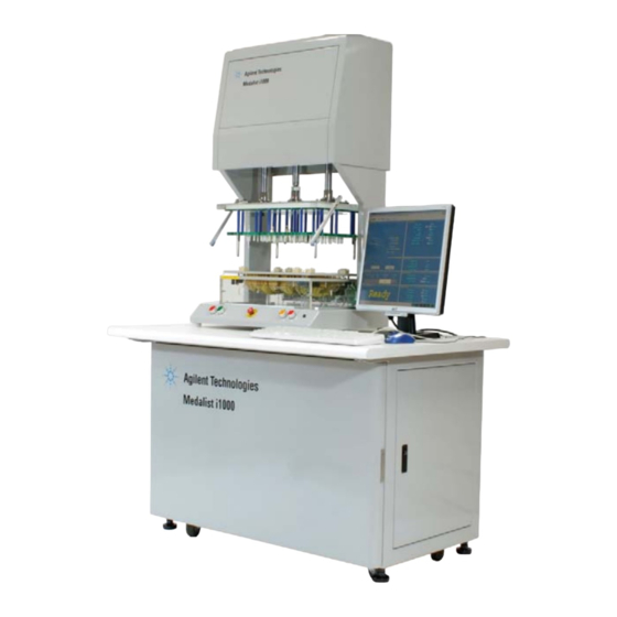
- Page 1 Medalist i1000 In-circuit Test System Installation Guide Agilent Technologies...
- Page 2 (June 1987) or DFAR 252.227-7015 (b)(2) prior agreement and written consent from imum extent permitted by applicable (November 1995), as applicable in any Agilent Technologies, Inc. as governed by law, Agilent disclaims all warranties, technical data. United States and international copyright either express or implied, with regard laws.
-
Page 3: Table Of Contents
System Check Adjusting Fixture Press Travel on the Press Down Model (U9401A) This guide describes how to install the Medalist i1000 In- circuit Test Systems. Procedures are provided for both the press down model (U9401A) and the vacuum model (U9402A). -
Page 4: Safety Precautions
This equipment is not intended for use near explosive or corrosive hazards. Servicing C A U T I O N All fuses must be replaced only with fuses of the specified type. Do not modify the equipment or use unapproved replacement parts. Medalist i1000 Installation Guide... -
Page 5: Front Panel Access
Front Panel Access The front panel of the Medalist i1000 provides access to the power switches and cards in the testhead. The front panel can also be removed when servicing is required. • Opening the Front Panel • Removing the Front Panel •... - Page 6 (Figure 4). Then unhook the cables from the screws. Figure 4 Unfasten supporting cables Once the supporting cables are released, use the handles to lift the front panel upwards and away from the test station. Medalist i1000 Installation Guide...
- Page 7 Support the front panel while you loop the supporting cables over the screws (Figure 3). Tighten the screws to secure the cables. Figure 6 Secure supporting cables Close the front panel. Open the side panels and secure the latches on the inside of the front panel. Medalist i1000 Installation Guide...
-
Page 8: Installation Overview
U9401A (press down model). On the U9402A (vacuum model), the controller is installed in the same location. Figure 7 U9401A (press down model) Press Down Unit Sensors Fixture Debug probe/ESD ground connector Monitor, keyboard, and mouse Medalist i1000 Installation Guide... - Page 9 Install the Press Down Unit (U9401A) Install the Controller Connect the Debug Probe Connect Power and Compressed Air Supply Power Up the System Install Medalist i1000 Software Install the Fixture Align the Safety Sensors Perform a System Check Installation procedure for Vacuum Model (U9402A)
-
Page 10: Preparing The Power Cord
Preparing the Power Cord The Medalist i1000 is shipped without a power cord. This allows local support WA R N I N G engineers to purchase a power cord that is suitable for use in the facility where the system is installed and meets the regulatory requirements of the country. - Page 11 Figure Ensure the wires are connected to the correct terminals as shown in WA R N I N G Figure 11. Otherwise the system could be damaged. Figure 11 Solder wires to terminals Earth Neutral Live Medalist i1000 Installation Guide...
- Page 12 Ensure that the retainer holds the power cord securely to prevent any movement C A U T I O N that may break the solder connections of the wires to the terminals in the connector. Figure 12 Reassemble connector cable retainer Medalist i1000 Installation Guide...
-
Page 13: Hardware Installation
Connect the other end to the rear of the Press Down Unit. See Figure 14 (a). Connect the compressed air hose to the connector at the rear of the Press Down Unit (a) and the rear of the test station (b). Medalist i1000 Installation Guide... - Page 14 Clamp the base to the right side or back of the test station. Assemble the support arm as shown. Tighten the screws with the Allen key provided. Set the monitor on top of the arm. Medalist i1000 Installation Guide...
- Page 15 3). Place the CPU in the right compartment of the test station. Figure 17 CPU Connect the keyboard, mouse, and monitor cables to the CPU. Connect the three flat cables from the CPU to the system card. Medalist i1000 Installation Guide...
- Page 16 Plug the power cables of the CPU and monitor firmly into the sockets labeled PC POWER OUTLET. Before connecting the power cables, check them for damage and ensure that WA R N I N G no internal wires are exposed. Figure 19 Power cables Medalist i1000 Installation Guide...
- Page 17 Connect the Debug Probe Connect the debug probe to the connector on the front of the press down model (a) or the control box (b) of the vacuum model. Figure 20 Connector for debug probe Medalist i1000 Installation Guide...
- Page 18 Connect the power cable from the test station to a power outlet. Figure 21 Main power cable Connect the compressed air supply to the inlet at the rear of the test station. Figure 22 Compressed air supply For the vacuum model, also connect the vacuum hose. Medalist i1000 Installation Guide...
- Page 19 Power Up the System Turn on the power to the system in the following order: MAIN POWER PC POWER SYSTEM POWER CPU power Testhead power Figure 23 Power up the system Medalist i1000 Installation Guide...
-
Page 20: Software Installation
Software Installation Before installing the Medalist i1000 software, set the screen resolution to to 1024 x 768 pixels and color quality to 16-bit color (Start > Control Panel > Display > Settings tab). Insert the Medalist i1000 Software disc in the controller’s drive. -
Page 21: Control Buttons
AUTO RELEASE – Automatically disengage and release the fixture. AUTO LINK – Automatically lock and engage the fixture. MOTOR RELEASE – Disengage the module from the tester interface. MOTOR LINK – Press and hold to engage the module. Medalist i1000 Installation Guide... -
Page 22: Installing The Fixture On The Press Down Model (U9401A)
25). Move the fixture so that the slots along the left and right sides of the top plate line up with the center holes of the honeycomb plate. Figure 25 View of honeycomb plate from the left Medalist i1000 Installation Guide... - Page 23 Connect the 64- pin flat cables from the back of the fixture to the testhead. Connect the cables according to the slot numbers shown on the back of the fixture. Turn the sensor switch back on. Medalist i1000 Installation Guide...
- Page 24 After installing the fixture, follow these steps to align the two safety sensors at the front of the Press Down Unit. Make sure the Medalist i1000 software is not running. N O T E Disable the sensors by flipping the sensor switch down (see (a) in Figure 43).
- Page 25 Loosen the screws on the other sensor arm, and adjust the position of the sensor until the two sensors are aligned (the RETEST button will stop blinking). Figure 29 Adjust second sensor Tighten the screws to secure the sensor in place. Medalist i1000 Installation Guide...
-
Page 26: Installing The Fixture On The Vacuum Model (U9402A)
Figure 30 Vacuum fixture Press the AUTO LINK button (a) to automatically lock and engage the fixture. Figure 31 Control box Releasing the Fixture To disengage and release the fixture, press the AUTO RELEASE button (b). Medalist i1000 Installation Guide... - Page 27 There is no indicator to signal if the module is fully engaged. Typically it will be fully engaged in about 6 seconds. Press MODUAL RELEASE to return the module holder to its locked position (see Figure 34 on page 27). Medalist i1000 Installation Guide...
- Page 28 (Figure 35 on page 27). Press MODUAL RELEASE to move the module holder to the locked position to hold the module in place. Figure 33 module holder fixture lock module support Medalist i1000 Installation Guide...
- Page 29 Figure 34 Module holder positions Module holder in unlocked position Module holder in locked position Figure 35 Module positions Module in unlocked position Module in fully engaged position Medalist i1000 Installation Guide...
- Page 30 U9402A Parts of the Vacuum Fixture ( The parts of the vacuum fixture are shown below. Figure 36 Vacuum fixture vacuum fixture vacuum fixture Figure 37 Metal base Medalist i1000 Installation Guide...
- Page 31 Figure 38 Lock down kit lock down Figure 39 Guard rail guard rail Medalist i1000 Installation Guide...
- Page 32 Figure 40 Air cushion air cushion Medalist i1000 Installation Guide...
-
Page 33: System Check
Figure 41 Pressure check Check that all sensors are functional by activating them. Log on to the Medalist i1000 software. From the Diagnostics menu, select I/O Cards. Click Read All. Upon activation of the sensor switches, the status of the sensors should change from OFF to ON or vice versa. -
Page 34: Adjusting Fixture Press Travel On The Press Down Model (U9401A)
Press both DOWN buttons to lower the press to the correct position. Move the lower position sensor (b) till the sensor light turns on. Secure the sensor. Reactivate the sensors by flipping the sensor switch up. Medalist i1000 Installation Guide... - Page 36 © Agilent Technologies, Inc. 2007 Printed in Taiwan 09/07 First edition, September 2007 U9401-96000 Agilent Technologies...