Nortel DMS-100 Series Maintenance Manual
Remote line concentrating module with extended distance capability
Hide thumbs
Also See for DMS-100 Series:
- Replacement procedures (1100 pages) ,
- Maintenance manual (762 pages) ,
- Manual (543 pages)

Related Manuals for Nortel DMS-100 Series


Summary of Contents for Nortel DMS-100 Series
- Page 1 297-8381-550 DMS-100 Family Remote Line Concentrating Module with Extended Distance Capability Maintenance Manual ABSK007 Standard 02.02 April 1999...
- Page 3 DMS-100 Family Remote Line Concentrating Module with Extended Distance Capability Maintenance Manual Publication number: 297-8381-550 Product release: ABSK007 Document release: Standard 02.02 Date: April 1999 1996, 1998, 1999 Northern Telecom All rights reserved Printed in the United States of America NORTHERN TELECOM CONFIDENTIAL: The information contained in this document is the property of Northern Telecom.
-
Page 5: Table Of Contents
Contents About this document When to use this document vii How to check the version and issue of this document vii References in this document viii What precautionary messages mean viii How commands, parameters, and responses are represented ix Input prompt (>) ix Commands and fixed parameters ix Variables ix Responses x... - Page 6 iv Contents Drawer testing 1-61 LCM REXTEST 1-62 System REX controller: XPM maintenance 1-64 Escalation to manual maintenance 1-70 Alarm conditions 1-70 Subscriber lines manual maintenance 1-71 Drawer maintenance 1-71 Signaling for RLCM-EDC Signaling for RLCM-EDC 2-1 Signaling and communications protocols 2-1 RLCM-EDC signaling links 2-1 Signaling protocol 2-4 Signaling functions 2-8...
- Page 7 Contents v NT6X51 in LCM 6-86 NT6X52 in LCM 6-91 NT6X53 card in LCM 6-96 NT6X54 in LCM 6-103 NT6X73 in HIE 6-109 NT6X74 in RMM 6-113 Replacing a card RLCM-EDC 6-121 Replacing a line card in an LCM 6-127 Locating and clearing RLCM-EDC problem procedures Trouble isolation and correction Description of troubleshooting procedures 8-1...
-
Page 9: About This Document
About this document When to use this document This Remote Line Concentrating Module with Extended Distance Capability (RLCM-EDC) maintenance reference manual provides: overview, signal- ing, and hardware information for understanding the RLCM-EDC product and operation; recovery procedure for returning to service an RLCM-EDC from a completely out-of-service condition;... -
Page 10: References In This Document
viii About this document organized, check the release information in Product Documentation Directory, 297-8991-001. References in this document The following documents are referred to in this document: PAlarm Clearing Procedures PCard Replacement Procedures POperational Measurements Reference Manual PInput/Output System Reference Manual, 297-1001-129 PTranslations Guide PProvisioning Guide, PLN–8991–104 What precautionary messages mean... -
Page 11: How Commands, Parameters, And Responses Are Represented
About this document ix WARNING Possibility of equipment damage WARNING Damage to the backplane connector pins Align the card before seating it, to avoid bending the backplane connector pins. Use light thumb pressure to align the card with the connectors. Next, use the levers on the card to seat the card into the connectors. -
Page 12: Responses
x About this document Responses Responses correspond to the MAP display and are shown in a different type: FP 3 Busy CTRL 0: Command request has been submitted. FP 3 Busy CTRL 0: Command passed. The following excerpt from a procedure shows the command syntax used in this document: Manually busy the CTRL on the inactive plane by typing >BSY CTRL ctrl_no... -
Page 13: Maintenance Overview
Maintenance overview Introduction The Remote Line Concentrating Module with Extended Distance Capability (RLCM-EDC) is a remote peripheral that provides extended geographic coverage for the Digital Multiplex System-100 (DMS-100) switch. The RLCM-EDC is configured to operate at a distance of 1,500 to 2,000 miles from the host office with a maximum engineered one-way path delay of up to 20 milliseconds. -
Page 14: Hardware Description
1-2 Maintenance overview RLCM-EDC to LTC+ hardware configuration DS30/DS512 Message links Network DS30/DS512 Speech links LTC + NT6X50AB NTMX77AA NTMX76BA 2 to 6 DS-1 Links NT6X51BA 2 DS30A Links NT6X50AB RLCM-EDC NT6X21 2-wire line Hardware description This section describes how the different hardware components of the RLCM-EDC interact for maintenance and troubleshooting. -
Page 15: Line Concentrating Module
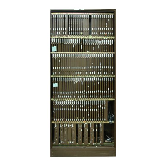
Maintenance overview 1-3 frame supervisory panel (FSP) The lower part of the cabinet contains the LCM, consisting of two line concentrating arrays (LCA). The upper part of the RLCC cabinet contains the HIE shelf, the RMM shelf, and the FSP. The FSP provides power control and alarm circuits for the LCM, HIE, and RMM shelves. - Page 16 1-4 Maintenance overview RLCC cabinet, shelf, and panel arrangement RLCC cabinet (NTNX14AA) Shelf position FSP (NTNX26AA) Frame Supervisory Panel RMM (NT6X13AA) Remote maintenance module Host interface equipment HIE (NT6X11AA) LSG 11 LSG 13 LSG 15 LSG 17 LSG 19 LCA 1 LSG 10 LSG 12 LSG 14 LSG 16 LSG 18 (NT6X04AA) LSG 01 LSG 03 LSG 05 LSG 07 LSG 09...
-
Page 17: Lca Shelf Configuration
Maintenance overview 1-5 In the RLCC, the LCM connects two to six DS-1 control-side (C-side) links to its 20 line sub-groups (LSG). The following LCM components make up this interface: 2 power converters 2 control complexes (LCM processor and digroup control card) 20 LSGs The RLCM-EDC has a minimum of two DS-1 links because each primary link carries one message channel to the LTC+ for the LCM unit and one for... - Page 18 1-6 Maintenance overview Line concentrating array (LCA) shelf layout LCA: NT6X04AA Power converter Even Even Even Even Even Slot: 01 02 04 05 Line drawers Slot Abbr NT PEC Remarks 01–03 6X53AA Power converter. Also contains ringing and ANI voltage switching circuits. LCMP 6X51BA LCM processor card (see note)
-
Page 19: Lcm Control Complex Cards
Maintenance overview 1-7 LCM control complex cards The LCM processor (LCMP) card and di-group control card (DCC) are often referred to as common cards in the LCA. In each LCA, the common cards, which are always provided. The following paragraphs describe the functions of these cards. - Page 20 1-8 Maintenance overview The NT6X51BA card contains two banks of FLASH ROM memory. Each bank can hold up to 4M of software and data. The NT6X51BA also contains a 2M bank of DRAM (Dynamic RAM). FLASH ROM devices can be reprogrammed multiple times. The two banks of FLASH ROM are configured so that only one FLASH ROM bank is active at any one time.
- Page 21 Color RED – lit when unit state is ManB, SysB or CBsy Service The terminal access connector is used for debugging and should be used by Northern Telecom (Nortel) personnel only. The activity status has two LEDs, one GREEN the other RED. When the GREEN LED is lit, the LCM processor is in an active In-Service (InSv) or In-Service-Trouble (ISTb) state.
- Page 22 LCM processor software. This function is a debugging tool only and the information provided through this port is raw data pulled directly from operating software memory areas. This port should be accessed by Nortel personnel only. Interfaces This section describes the following NT6X51BA interfaces:...
- Page 23 Maintenance overview 1-11 Delay tolerant C-side messaging The RLCM-EDC uses the LAPD protocol, the International Telecommunications Unit (ITU) standard Q.921, as the data link layer. This is an HDLC-based protocol and through the use of sliding-window protocols allows communications over long distances and large propagation times as much as 20 milliseconds, one-way.
- Page 24 1-12 Maintenance overview New load sources for the LOADPM command An RLCM-EDC contains two banks of flash ROM with 4M capacity each. Each bank can contain a complete RLCM-EDC load. The bank being used by the processor is the active bank and is in the active mode. The other bank is the standby bank and is in the standby mode.
- Page 25 Maintenance overview 1-13 Commands This section addresses the following commands associated with RLCM-EDC: LOADPM SWLD QUERYPM LOADPM command The LOADPM command is used to send a load to the flash ROM bank in an RLCM-EDC. This command can be performed on an in-service (InSv) or out-of-service (OOS) RLCM-EDC unit.
- Page 26 1-14 Maintenance overview New options are added to the LOADPM command to make use of the sophisticated architecture of the LCM processor card. To simplify the number of outcomes resulting from a LOADPM command, based on the combinations of its options. The SOURCE option of the LOADPM command is changed from an optional to a required parameter.
- Page 27 Maintenance overview 1-15 Load sources for the RLCM-EDC Parameter Value Description Source CC, MATE, The SOURCE parameter is a required parameter. SELFACT Functionality of the command with a source value of CC remains unchanged. When the MATE option is used without specifying the BANK parameter, the command defaults to STBY.
- Page 28 1-16 Maintenance overview Loading continues while the prompt is returned to operating company personnel when the NOWAIT option is used, such as in the following example. >LOADPM UNIT 1 CC NOWAIT Example of MAP response LCM REM1 0 0 Unit 1 Request Submitted. LOADPM command error messages The following responses are observed when an attempt is made to load an RLCM-EDC LCM or unit and fails.
- Page 29 Maintenance overview 1-17 The following response is observed for the LOADPM command when the mate unit is OOS and the SELFACT option is used. When this response is observed, operating company personnel must RTS the OOS unit then execute the LOADPM command with the SELFACT option. >LOADPM UNIT 1 SELFACT Example of MAP response LCM REM1 0 0 Unit 1...
- Page 30 1-18 Maintenance overview option can only be used if both units are in the same state such as, InSv, ISTb or ManB. If the LCM being loaded has two different states such as, one unit InSv and one unit OOS, the operating company personnel must use the option and load each unit separately.
- Page 31 Maintenance overview 1-19 The following MAP display response is observed when the BSY command is executed with the ALL option but not the SMEM suboption. >BSY UNIT 0 ALL Example of MAP response This will cause ALL LCMs in the posted set to be busied. The SMEM option of the BSY command should be used if loading the 4M LCMs in-service is desired.
- Page 32 1-20 Maintenance overview RTS command The RTS command retains all existing functionality. The new options SMEM and SWLD are added to the RTS command to return to service only the smaller memory (64K/256K) LCMs and activate new loads in 4M LCMs. The SMEM option is applicable only when option ALL is used.
- Page 33 Maintenance overview 1-21 RTS command error messages The RTS command rejects any attempt to return to service a unit which has an invalid load in the active and standby banks. A new response is generated when attempting to RTS a RLCM-EDC unit which has an invalid load in the active and standby banks.
- Page 34 1-22 Maintenance overview SWLD command The SWLD command is a new command available at the LCM level of the MAP display menu in position 13 and is applicable only to RLCM-EDC nodes. When this command option is used on an InSv node, it places the RLCM-EDC in a simplex mode for a short period of time.
- Page 35 Maintenance overview 1-23 Example of MAP response LCM REM1 01 0 Unit 1 Request Invalid Mate unit must be either InSv or ISTb The ALL option is used to execute the command on a set of posted LCMs. The set may include LCMs of different types (64K, 256K, 4M). The command however executes only on 4M LCMs.
- Page 36 1-24 Maintenance overview SWLD command error messages The following responses are observed when an attempt is made to SWLD an RLCM-EDC LCM or unit and fails. The following response is observed when an attempt is made to SWLD an RLCM-EDC unit with invalid loads in both the active and standby banks. >SWLD UNIT 0 Example of MAP response LCM REM1 05 0: Request Invalid...
- Page 37 Maintenance overview 1-25 The following response is observed when an attempt is made to SWLD a non-RLCM-EDC unit. >SWLD UNIT 0 Example of MAP response LCM HOST 05 0 Unit 0: Request Invalid LCM MEMSIZE must be 4M in table LCMINV The following response is observed when an attempt is made to SWLD an RLCM-EDC unit and the system is unable to check the loadnames from the LCM unit...
- Page 38 1-26 Maintenance overview QUERYPM command Output for the QUERYPM command is different for a RLCM-EDC as compared to an existing SMEM LCM. The command functionality remains unchanged for existing smaller memory (64K and 256K) LCMs, as seen in the example below. >QUERYPM Example of MAP response 4M LCM...
- Page 39 Maintenance overview 1-27 The QUERYPM command displays information about the posted RLCM-EDC. The output indicates that the memory sizes of the two units as . The MAP display also includes the loadfile names contained in the ACT and STBY banks of flash ROM of each unit. The command, used QUERYPM without options, does not output any loadfile information for out-of-service...
- Page 40 1-28 Maintenance overview Example of MAP response >QUERYPM PM Type: LCM Int. No.: 9 Status index: 7 Node_No: 40 LCM REM1 02 0 Memory Size – Unit 0: 4M , Unit 1: 4M ESA equipped: No, Intraswitching is Off Loadname: LCMINV – REDC07AA Unit0 Loads: Act–...
- Page 41 Maintenance overview 1-29 Misc. Cside Link Errors IUC FrmSendCnt IUC FrmReSendCnt IUC FrmRcvCnt IUC ErrInvalidFrmSizeCnt IUC Receipt Unsolicited Response IUC Peer Initiated Reestablishment IUC Unsuc. Retransmissions Misc. IUC Link Errors Example of MAP display >QUERYPM CNTRS Current Message Thresholds ade... Unsolicited: Unit 0 = 1, Unit 1 = 1 (limit = 200) Data:...
- Page 42 1-30 Maintenance overview Options of the QUERYPM command Parameter Value Description This option reports fault reasons when the unit being queried is ISTB or SYSB. CNTRS CNTRS This option queries the values of the LAPD counters from an InSv unit DRWR DRWR This option queries drawer information.
- Page 43 Maintenance overview 1-31 Error detection Error detection methods for the LTC+ are unchanged except for logic added to test the unique circuits on the NT6X50AB DS-1 interface and NTMX76BA cards. Error detection for the RMM remains unchanged from the standard RLCM application. Error detection for the LCM portion of the RLCM-EDC is modified since there are three different processors on the NT6X51BA cards.
- Page 44 1-32 Maintenance overview Digroup control card The DCC (NT6X52) is located in slot 05 of the LCA shelf. The DCC allows the LCA and HIE shelves to communicate. The DCC provides an interface between its corresponding LCM processor in the LCA and one link control card (LCC) in the HIE through eight DS30A links, as shown in the following figure, “RLCM-EDC DS30A to DS-1 interface.”...
-
Page 45: Line Drawers
Maintenance overview 1-33 Line drawers Each line drawer (NT6X05) in the LCA shelf has one bus interface card (BIC) and a maximum of 64 line cards of various types. The following figure shows the side view of a typical LCA line drawer. The line drawer can be withdrawn from the frame to access line circuit cards, yet remain operative because of flexible cables connected to the rear receptacles. - Page 46 1-34 Maintenance overview At the LCM level of the MAP display, the status of the drawers is displayed below the status of the LCM units. The drawers are numbered from 0 through 19 and grouped in pairs to show that they share the same BIC card and, normally, interface a different processor (odd or even).
- Page 47 Maintenance overview 1-35 Line cards The line cards are located behind the BIC card in 4 rows of up to 16 line cards in each row. The top two rows of line cards form the odd-numbered LSG, and the bottom two rows form the even-numbered LSG. Normally, LCA-1 control complex controls the odd LSG of both arrays, and LCA-0 control complex controls the even LSGs of both arrays, using the ten 32-channel P-side ports available on the DCC of each array.
-
Page 48: Functional Description
1-36 Maintenance overview A complete LEN for an RLCM-EDC line card consists of five units of information, as described in the following table. The example shows LENs for line cards in a typical office. The first two LENs are for RLCM-EDC-supported lines. - Page 49 Maintenance overview 1-37 Functional block diagram Control complex Line drawers Ports (0–7) 6–9 Drawer 9 1–3 DS30A 0,1,2 LCC -1 Drawer 5 Line NT6X51 NT6X52 LSG 11 NT6X54 card 0 Digroup Bus I/F processor control card LSG 10 card card Line 3,4,5 card 0...
-
Page 50: Hie Description
1-38 Maintenance overview HIE description The HIE occupies a single shelf at position 33 in the RLCM-EDC frame. The HIE allows the LCA shelves of the RLCM-EDC to connect both to the remote maintenance module (RMM) and to the host office. The HIE shelf contains the following components: two power converters two LCCs... - Page 51 Maintenance overview 1-39 HIE shelf layout HIE: NT6X11AA Power Power Filler panels converter converter 01 02 03 04 05 06 07 08 09 10 11 12 13 14 15 16 17 18 19 20 21 22 23 24 25 Slot NT PEC Remarks Abbr...
- Page 52 1-40 Maintenance overview LCC interface to DS-1 interface cards To host office DS-1 links 0 DS-1 DS-1 DS-1 interface interface interface card card card LCC-0 LCC-1 I/S: intershelf link DS30A links DS30A links LCA-0 LCA-1 Under normal conditions, when both are active, LCC-0 connects LCA-0, and LCC-1 connects LCA-1.
- Page 53 Maintenance overview 1-41 RLCM-EDC link, port and channel structure ports DS-1 24 channels link Equipped DS-1 Primary 24 channels link Equipped ports DS-1 link 24 channels Equipped To mate Image links 1, ports DS30A 3, and 5 320 lines Inter-unit link Interlink port RMM link RMM port...
- Page 54 1-42 Maintenance overview The LCC also provides system clocks for the DCC, RMM, and LCM. When both units of the LCM are active, LCC-0 is frequency-locked to its primary DS-1 link, and the LCC-1 clock is locked to LCC-0. Thus, both LCC clocks derive their timing from the same source, which is the host LTC+.
-
Page 55: Remote Maintenance Module
Maintenance overview 1-43 Primary ports that map one to one with DS-1 links are known as equipped ports. The number of equipped ports in an LCA depends on the number of DS-1 interface cards provisioned in the HIE. If three DS-1 cards are provisioned, all three primary ports (0, 1, 2) for each LCA are equipped. - Page 56 1-44 Maintenance overview RMM connection with host and LCA through LCC DS30A link pair LCA-0 DS-1 links Link control Host DS30A links cards LCA-1 The RMM uses DMS-X protocol to communicate with the host, using the LCC interface to the DS-1 links. The RMM can accommodate up to 14 maintenance and service circuit cards.
- Page 57 Maintenance overview 1-45 Remote maintenance module shelf layout RMM: 6X13AA Remarks Slot Abbr NT PEC 2X59AA Group codec and tone card RMMC 6X74AB RMM control card 2X90AD Test trunk circuit 2X90AD Test trunk circuit 3X09BA Metallic test access (8x8) 0X10AA Scan detector card MTUA 2X10BA...
- Page 58 1-46 Maintenance overview RMM control card The RMM control card (NT6X74AB), located in slot 02, is required in the RMM. The RMM control card acts as an interface between the line concentrating array shelves and the test trunks, service circuits, and alarm circuits of the RMM.
- Page 59 Maintenance overview 1-47 Scan Detector Card (NT0X10). The scan detector (SC) card provides an interface where the DMS-100 Switch Alarm System software can monitor the state of the RLCM-EDC hardware to detect alarm conditions or manually controlled operations. The SC card is divided into two circuits, each known as an SC group.
-
Page 60: Multiplex Facility Transmission Equipment
1-48 Maintenance overview Multiplex facility transmission equipment The LTC+ and RLCM-EDC equipment interface DS-1 facilities formatted in extended super frame (ESF) transmission format (24 frames). The DS-0 channels in these DS-1 facilities are configured for 64-kbit/s clear channel data using bipolar 8-bit zero suppression (B8ZS) channel coding method. Outside the DMS-100 isolated ground zone (IGZ) at the host site and RLCM-EDC remote site, the DS-1 links are terminated into transmission multiplex equipment. - Page 61 Maintenance overview 1-49 The FSP has circuit breakers (CB) to distribute –48V power to shelves in the RLCC cabinet. Refer to the following figure, “FSP shelf layout,” and table “FSP circuit breaker assignments,” for CB power distribution, assignments, shelf type and slot position, PEC code and equipment supported. FSP shelf layout Frame fail 01 +5V 05 06...
-
Page 62: Cooling Unit
1-50 Maintenance overview Cooling unit The NTNX27AA cooling unit (CU) is located at the bottom of the RLCC cabinet. The CU includes six circulation fans as seen in the figure “RLCC cooling unit” providing forced-air convection cooling for the four shelves of cards in the RLCC. -
Page 63: Software Description
Maintenance overview 1-51 Software description The following sections describe the software operation of the NTX146AB feature package. Interface to DS-1 links The RLCM-EDC provides an interface between the host controller and up to 640 subscriber lines (140 P-phones in the initial application) through the DS-1 links. -
Page 64: Functional Limitations
1-52 Maintenance overview Subscriber tones The host LTC+ provides properly cadenced tones, which the RLCM-EDC applies as needed to subscriber lines. The tones supported by the host LTC+ are: dial tone audible ringing warble (MDC Meridian business set ringing) busy tone reorder tone receiver off-hook (ROH) tone The RLCM-EDC is subordinate to the DMS-100 switch CC and is not... -
Page 65: Fault Conditions
Maintenance overview 1-53 NTX901AA: Local Features I Fault conditions Several types of faults can occur in the components of the RLCM-EDC. DS1 links from the LTC in the host office to the RLCM-EDC can become faulty. If they do, messaging from the CC can be lost, and subscriber service can also be lost. -
Page 66: Link Failure
1-54 Maintenance overview Link failure Link failures include the following: DS-1 links Link failures are usually associated with the DS-1 interface cards in the host controller, DS-1 link, or DS-1 interface cards in the RLCM-EDC. Monitoring is performed through operational measurements (OM) that indicate when maintenance or out-of-service thresholds have been exceeded. -
Page 67: Load File Mismatch
Maintenance overview 1-55 Load file mismatch A load file mismatch fault condition exists when a load in the active bank of the LCM does not match the load specified in table LCMINV. Automatic maintenance The DMS-100 Family peripheral modules (PM) are designed to be reliable under many different fault conditions. -
Page 68: Checksums
1-56 Maintenance overview DS-1 interface card maintenance For each of its DS-1 interface cards, the RLCM-EDC automatically monitors the BpV counter and notifies the CC when the count exceeds the threshold of 1 BpV per 10 bits (10 kbits). The RLCM-EDC also monitors the loss-of-frame indicator and loss-of-signal indicator (red alarm) for the DS-1 links and turns on an outgoing alarm for any frame or signal loss of more than 2.5 seconds. -
Page 69: Lcm Ltc Speech Path Diagnostics Enhancements
Maintenance overview 1-57 LCM LTC speech path diagnostics enhancements The LTC diagnostic tests consist of the following two parts: Speech path diagnostic (SPCHDIAG). Tests all internal components of the LTC speech path for data integrity, including C-side and P-side looparounds and speech bus timeslots. P-side link diagnostic (PLNKDIAG). -
Page 70: Overload Resources
1-58 Maintenance overview Internal loop test This test checks the integrity of LTC+ speech channels. If the LTC+ is out of service (OOS), a full test on every channel is run. If the LTC+ is InSv, the test checks two speech channels selected at random. The internal loop test also checks the operation of LTC+ PCM enable/disable gates. -
Page 71: Takeover Capability
Maintenance overview 1-59 than entrance criteria at each level). Overload is detected by measuring the number of times the size of the message queue exceeded a specific value during the measurement period, which is 20 seconds. The threshold value for number of messages on the queue, and for the number of times the queue exceeded that number is defined by four values, which are: LOW_ENTRY_THRESHOLD... -
Page 72: Rmm Maintenance
1-60 Maintenance overview takeover. In the takeover state, the InSv unit assumes control of the lines associated with the OOS mate unit, in addition to its own. Also, the InSv unit has access to the DS30A C-side ports formerly used by the OOS mate. All 20 line subgroups are accessed by the DCC of the InSv unit. -
Page 73: Drawer Testing
Maintenance overview 1-61 Drawer testing To ensure that message and speech data can be sent to and from the BIC, the RLCM-EDC conducts a BIC looparound test to detect line drawer faults. If the BIC test fails, the CC implements a full in-service test on both BICs, to ensure the fault is not transient or from the DCC or processor card. -
Page 74: Lcm Rextest
1-62 Maintenance overview checksum_inactive_bank lcc_fault_code comm_iuc_la_tst bic_scan_test_all bic_act_test_all power_converter_test test_lc ring_mux_relays_test cside_link_looparound_test msg_test Faults that occur on a BIC drawer affect call processing regardless of which unit is in service and controlling that drawer. Since the full in-service tests use the DCC, it must first be determined that the fault is not in the DCC, where takeover is justified. - Page 75 Maintenance overview 1-63 LCMREX test flow A REX test for an LCM includes the following procedure: 1 If both units of the LCM are in service, unit 0 is made SysB; a PM128 state change log is generated with the reason , the REX in progress LCM node status is made ISTb, and a minor alarm is generated.
-
Page 76: System Rex Controller: Xpm Maintenance
1-64 Maintenance overview System REX controller: XPM maintenance Feature AF3771, System REX Controller: XPM Maintenance, provides the SuperNode switch with an S/DMS system REX test (SREX) controller which coordinates all system REX tests under a common REX test scheduler. This feature allows LCM REX tests to be scheduled while other REX tests are in progress. - Page 77 Maintenance overview 1-65 The IOAU112 log report for LCMs is generated if the LCM has not been REX tested for more than seven days REX test takes longer than specified REX test could not be started after a defined number of attempts LCM REX test dependencies To avoid conflicts, all concurrent REX tests of XPMs and LCMs are scheduled by the SREX controller.
- Page 78 1-66 Maintenance overview Line concentrating module (LCM) REX test scheduling Scheduling of SREX tests for LCMs is controlled by table REXSCHED. The LCM_REX_TEST task SREX can be executed concurrently in multiples of four and simultaneously with REX tests of XPMs. Conflicts arise when an XPM scheduled for REX testing is the host of an LCM scheduled for REX testing.
- Page 79 Maintenance overview 1-67 MAP commands for manual REX tests LCM diagnostics provide the capability to implement a manual LCM REX test. A manual REX test is accomplished by adding a REX parameter to the TST command at the PM level of the MAP display. Examples of this command are as follows: ATTENTION The REX test will remove a unit from service and should be executed...
- Page 80 1-68 Maintenance overview The node assessment graph log (NAG400) is generated hourly, or in response to the NAG command, to list all nodes that are not in-service (InSv). Field REX_INFO of log NAG400 displays the results of the latest REX test. For LCMs, the LCM_REX_TEST result is listed first. For more information about NAG400 logs, refer to the Log Reports Reference Manual.
- Page 81 Maintenance overview 1-69 The following output depicts an abbreviated report in response to the NAG command. Front End Load: FSL37AO Level Node Status REX INFO UNIT 0 UNIT 1 NORMAL NORMAL NORMAL NORMAL NORMAL PM RCC SYSB SYSB SYSB KOPM 12 0 SYSB PASS: PASS...
-
Page 82: Escalation To Manual Maintenance
1-70 Maintenance overview Escalation to manual maintenance When automatic maintenance fails to correct a fault in the DMS switch, the DMS switch provides trouble indicators that reveal a fault condition still exists. Alarms are examples of trouble indicators. Some OMs and logs also indicate a fault condition and a failure of automatic maintenance. -
Page 83: Subscriber Lines Manual Maintenance
Maintenance overview 1-71 Alarm class codes, displays, and conditions PM header display Condition All PMs are in service. No alarm conditions are in effect. More than 10% of the PMs are SysB–critical alarm. nnSysB Both units of one or more LCMs are not in-service critical alarm. -
Page 85: Signaling For Rlcm-Edc
Signaling for RLCM-EDC Signaling for RLCM-EDC This section describes the signaling protocols that the Remote Line Concentrating Module with Extended Distance Capability (RLCM-EDC) uses. The RLCM-EDC uses the protocols to communicate with the DMS-100 switch and to provide subscriber services. The following subsections describe RLCM-EDC signaling and the types of subscriber services the signaling protocols provide. - Page 86 2-2 Signaling for RLCM-EDC Each DS-1 interface card can accept a maximum of two DS-1 links from the host LTC+. The RLCM-EDC and the host LTC+ exchange information over the DS-1 links through dedicated message channels. This signaling information allows the RLCM-EDC and the host LTC+ to perform the following tasks: communicate the states of subscriber lines perform call processing...
- Page 87 Signaling for RLCM-EDC 2-3 DS-1 frame format Framing Voice channel 1 Voice channel 2 Voice channel 24 1 2 3 4 5 6 7 8 9 10 11 12 13 14 15 16 185 186 187 188 189 190 191 192 193 Channel frame Channel frame Ft frame 1 Fs frame 2 Ft frame 3 Fs frame 4...
-
Page 88: Signaling Protocol
2-4 Signaling for RLCM-EDC The data link layer (level 2) provides the mechanism required to transfer messages from one node to another node. This other node connects directly to the first node. The network layer selects the route for the transfer of messages. - Page 89 Signaling for RLCM-EDC 2-5 DMS-X protocol The DMS-X protocol is a state-driven code. The DMS-X protocol requires handshake messaging between the RLCM EDC and host LTC+ at each stage of data transfer. This handshake messaging allows the terminals that communicate to delay the message transfer if one terminal is not ready. The following figure illustrates a general form of handshaking protocol.
- Page 90 2-6 Signaling for RLCM-EDC DMS-X message format Byte Destination task ID Source task ID Message header Node number Drawer number task ID Line number Message data byte (variable length) Actual message EOM = End of message SOM = Start of message LCM = Line concentrating module...
- Page 91 Signaling for RLCM-EDC 2-7 Extended frame format The DS-1 extended super frame format (ESF) has 24 frames. The 24 sync-bits are used as follows: 6 bits for framing pattern sequence (FPS) The fourth framing bit carries a FPS bit. Every fourth framing bit, after the fourth bit, carries a FPS bit.
-
Page 92: Signaling Functions
2-8 Signaling for RLCM-EDC Superframe alignment pattern Frame number Framing bit type Framing bit value CB = check bits m = message byte Signaling functions Signaling supports call processing activities. Signaling allows the functions of call origination, tone generation, digit collection, and ringing to occur. 297-8381-550 Standard 02.02 April 1999... - Page 93 Signaling for RLCM-EDC 2-9 Call origination Messaging transmits the on- and off-hook messages that allow the host XPM to identify subscribers that require service. When a subscriber lifts the handset from the cradle, a voltage source provides a steady flow of current through the transmitter. The voltage source is in the RLCM.
-
Page 94: Ds-30A Links
2-10 Signaling for RLCM-EDC recordings on tape at the machine. After each DTMF signal of 130 ms, a reconnection of the PCM signal occurs. DS-30A links The DS30A channel frames carry speech information or message information. The following figure is the format of a DS30A frame. The DS30A links operate at a rate of 2.56 Mbyte/s with a sampling frequency of 8000 frames each second. -
Page 95: Rlcm-Edc Hardware
RLCM-EDC hardware This chapter describes the Remote Line Concentrating Module with Extended Distance Capability (RLCM-EDC) hardware components. The RLCM–EDC hardware components give subscribers the full resources of the digital switching system. The following sections describe hardware components and additional components of the RLCM-EDC. RLCM-EDC hardware components The RLCM-EDC is in a Digital Multiplex System (DMS) remote line controller cabinet (RLCC). - Page 96 3-2 RLCM-EDC hardware RLCC cabinet, shelf, and panel arrangement RLCC NTNX14AA Shelf position FSP (NTNX26AA) Frame supervisory panel RMM (NT6X13AA) Remote maintenance module Host interface equipment HIE (NT6X11AA) LSG 11 LSG 13 LSG 15 LSG 17 LSG 19 LCA 1 LSG 10 LSG 12 LSG 14 LSG 16 LSG 18 (NT6X04AA) LSG 01 LSG 03 LSG 05 LSG 07 LSG 09...
-
Page 97: Line Concentrating Module
RLCM-EDC hardware 3-3 Line concentrating module The LCM is the basic design building block of the remote peripheral group. The control side (C-side) of an LCM interfaces with the host network over DS30A links. The RLCM-EDC connects over two to six DS-1 links to the host network. -
Page 98: Hie
3-4 RLCM-EDC hardware Note: The NT6X21 EBS card is the only applicable line card in the first application of the RLCM-EDC. Line cards Each of the ten line drawers of the LCM contains a pair of line subgroups (LSG) and a single BIC. Each LSG contains 32-line card slots that support a maximum of 640 subscriber line slots. -
Page 99: Rmm
RLCM-EDC hardware 3-5 An optional component of the RLCM-EDC is the RMM. The RMM is in the RMM shelf assembly. The RMM is a single-shelf module based on the maintenance trunk module (MTM). The RMM provides maintenance and service capabilities for the RLCM-EDC. The RMM consists of two power converters, an RMM control card, a codec and tone card. - Page 100 3-6 RLCM-EDC hardware NTNX27AA components Note: This figure is not to scale. 297-8381-550 Standard 02.02 April 1999...
-
Page 101: Rlcm-Edc Recovery Procedures
RLCM-EDC recovery procedures This chapter describes recovery procedures for the Remote Line Concentrating Module with Extended Distance Capability (RLCM-EDC). Maintenance personnel can use this procedure in a DMS-100/200 office. DMS-100 Family Maintenance Manual ABSK007... -
Page 102: Rlcm-Edc Recovery Procedure
RLCM-EDC recovery procedures RLCM-EDC recovery procedure Alarm display Trks Appl nLCM Application Use this procedure to recover service in an RLCM-EDC when both units of the RLCM-EDC are out of service. This condition produces a central-side busy (CBsy) alarm. Use this procedure only when an alarm clearing procedure refers to the procedure. - Page 103 RLCM-EDC recovery procedures 4-3 RLCM-EDC recovery procedure (continued) Summary of an RLCM–EDC recovery procedure This flowchart summarizes the procedure. Use the instructions that follow At PM level of this flowchart to perform the MAP, display procedure. CBsy LCMs Post host LTC Busy, test, and CBsy RTS link with...
- Page 104 4-4 RLCM-EDC recovery procedures RLCM-EDC recovery procedure (continued) Summary of an RLCM–EDC recovery procedure (continued) End of passed? procedure CBsy fault? Query LCM for Load correct loadfiles failure? Are loadfiles Card list? correct? Contact Load LCM maintenance support group Load RTS the LCM passes? unit with the...
- Page 105 RLCM-EDC recovery procedures 4-5 RLCM-EDC recovery procedure (continued) RLCM-EDC recovery procedure At the MAP terminal To silence an audible alarm, type >MAPCI;MTC;SIL and press the Enter key. To access the peripheral module (PM) level of the MAP display, type >PM and press the Enter key.
- Page 106 4-6 RLCM-EDC recovery procedures RLCM-EDC recovery procedure (continued) To display the peripheral side (P-side) links, type >TRNSL P and press the Enter key. Example of a MAP response: Link 2:LCM REM1 00 0 0;Cap MS;Status:SysB;MsgCond:CLS Link 6:LCM REM1 00 0 1;Cap MS;Status:SysB;MsgCond:CLS Note: Record information for the links that have a status other than OK.
- Page 107 RLCM-EDC recovery procedures 4-7 RLCM-EDC recovery procedure (continued) To return the busy link to service (RTS), type >RTS LINK link_no and press the Enter key. where link_no is the number of a defective P-side link tested in step 9 Note: Repeat this step for each tested link. If RTS passed and other links are not SysB step 11...
- Page 108 4-8 RLCM-EDC recovery procedures RLCM-EDC recovery procedure (continued) To busy both LCM units of the RLCM-EDC, type >BSY PM and press the Enter key. To query the out-of–service (OOS) LCM for correct load information, type >QUERYPM OOS and press the Enter key. Example of a MAP response: PM Type: LCM Int.
- Page 109 RLCM-EDC recovery procedures 4-9 RLCM-EDC recovery procedure (continued) Check if links to the RLCM-EDC are stable. To find and record the link numbers for this RLCM-EDC, type >TRNSL C and press the Enter key. Example of a MAP response: Host LTC P-side link number Link LTC 1 0;Cap MS;Status:OK ;MsgCon:OPN...
- Page 110 4-10 RLCM-EDC recovery procedures RLCM-EDC recovery procedure (continued) To post the host LTC+ links to the RLCM-EDC and check link conditions for slips and framing errors, type >POST LTC ltc_no link_no and pressing the Enter key. where pm_no is the number of the LTC+ (0 to 255) link_no is the number of the link associated with the host LTC+ (refer to step 16 display)
- Page 111 RLCM-EDC recovery procedures 4-11 RLCM-EDC recovery procedure (continued) To attempt to RTS the RLCM-EDC and switch load to the standby bank, type >RTS PM SWLD and press the Enter key. Example of a MAP response: Existing loads: Unit 0: Act:REDC07AA *FLT* Stby:REDC07AA Unit 1: Act:REDC07AA *FLT* Stby:REDC07AA...
- Page 112 4-12 RLCM-EDC recovery procedures RLCM-EDC recovery procedure (continued) To attempt to reload the RLCM-EDC, type >LOADPM PM CC press the Enter key. If load passes step 23 fails in one unit step 30 fails step 24 To attempt again to RTS the RLCM-EDC and activate the loads in the standby banks, type >RTS PM SWLD and press the Enter key.
- Page 113 RLCM-EDC recovery procedures 4-13 RLCM-EDC recovery procedure (continued) Switch OFF the circuit breaker to power down the converter in the LCM unit of the RLCM-EDC. Use the following table to determine which frame supervisory panel (FSP) circuit breaker serves the unit. Circuit breaker Unit LCA 0...
- Page 114 4-14 RLCM-EDC recovery procedures RLCM-EDC recovery procedure RLCM-EDC recovery procedure (end) (continued) To attempt to return the LCM unit to service and switch load to standby bank, type >RTS UNIT lcm_unit SWLD press the Enter key. where lcm_unit is the LCM unit to be returned to service (0 or 1) Example of a MAP response: Existing loads: Unit 0: Act:REDC07AA *FLT* Stby:REDC07AA...
-
Page 115: Rlcm-Edc Alarm Clearing Procedures
RLCM-EDC alarm clearing procedures This chapter contains the alarm clearing procedures for the Remote Line Concentrating Module with Extended Distance Capability (RLCM-EDC). The alarm indicates the procedure required to clear the trouble. Maintenance personnel use these procedures to clear alarms as the alarms appear at the MAP display. -
Page 116: Pm Lcm Critical
RLCM-EDC alarm clearing procedures PM LCM critical Alarm display Trks Appl nLCM Indication Use this procedure to recover service in an RLCM-EDC when both units of the line concentrating module (LCM) are out of service. This condition always produces a central side busy (CBsy) alarm. The LCM alarm appears under the PM header in the MAP subsystem display. - Page 117 RLCM-EDC alarm clearing procedures 5-3 PM LCM critical (continued) Summary of clearing a PM LCM critical alarm This flowchart summarizes the procedure. Use the instructions that follow At PM level of this flowchart to perform the MAP, display procedure. CBsy LCMs Post host LTC Busy, test, and CBsy...
- Page 118 5-4 RLCM-EDC alarm clearing procedures PM LCM critical (continued) Summary of clearing a PM LCM critical alarm (continued) End of passed? procedure CBsy fault? Query LCM for Load valid loadfiles failure? Are loadfiles Card list? valid? Contact Load LCM maintenance support group Load RTS the LCM...
- Page 119 RLCM-EDC alarm clearing procedures 5-5 PM LCM critical (continued) Clearing a PM LCM critical alarm At the MAP terminal To silence an audible alarm, type >MAPCI;MTC;SIL and press the Enter key. To access the PM level of the MAP display, type >PM and press the Enter key.
- Page 120 5-6 RLCM-EDC alarm clearing procedures PM LCM critical (continued) To display the peripheral side (P-side) links of the LTC+, type >TRNSL P and press the Enter key. Example of a MAP response: Link 2: LCM REM1 00 0 2; Cap MS; Status: SysB ;MsgCond: CLS Link 6: LCM REM1 00 0 1;...
- Page 121 RLCM-EDC alarm clearing procedures 5-7 PM LCM critical (continued) To return to service (RTS) the busied link, type >RTS LINK link_no and press the Enter key. where link_no is the number of a P-side link tested in step 9 Note: Repeat this step for each link correctly tested. If RTS passes and no other links are system busy (SysB) step 11...
- Page 122 5-8 RLCM-EDC alarm clearing procedures PM LCM critical (continued) To query the LCM for correct loadfile names, type >QUERYPM OOS and press the Enter key. Example of a MAP response PM Type: LCM Int. No.: 9 Status index: 7 Node_No: 40 LCM REM1 02 0 Memory Size –...
- Page 123 RLCM-EDC alarm clearing procedures 5-9 PM LCM critical (continued) Check to see if links to the RLCM-EDC are stable. To find and record the link numbers for this RLCM-EDC, type >TRNSL C and press the Enter key. Example of a MAP response Link LTC 1 0;Cap MS;Status:P,...
- Page 124 5-10 RLCM-EDC alarm clearing procedures PM LCM critical (continued) To post the host LTC+ links and check link conditions for slips and framing errors, type >POST LTC ltc_no link_no and press the Enter key. where ltc_no is the number of the LTC+ (0 to 255) link_no is the number of the link associated with the host XPM (see step 16 display)
- Page 125 RLCM-EDC alarm clearing procedures 5-11 PM LCM critical (continued) To attempt to RTS the RLCM-EDC and switch load to the standby bank, type >RTS PM SWLD and press the Enter key. Example of a MAP response: Existing loads: Unit 0: Act:REDC07AA *FLT* Stby:REDC07AA Unit 1: Act:REDC07AA *FLT* Stby:REDC07AA...
- Page 126 5-12 RLCM-EDC alarm clearing procedures PM LCM critical (continued) To attempt to reload the RLCM-EDC, type >LOADPM PM CC and press the Enter key. If load passes step 23 fails in one unit step 30 fails step 25 To attempt to RTS the RLCM-EDC again, and switch load to standby banks, type >RTS PM SWLD and press the Enter key.
- Page 127 RLCM-EDC alarm clearing procedures 5-13 PM LCM critical (continued) To power down the converter in the LCM unit of the RLCM-EDC you are working on, switch OFF the circuit breaker. Use the following table to determine which frame supervisory panel (FSP) circuit breaker serves the unit.
- Page 128 5-14 RLCM-EDC alarm clearing procedures PM LCM PM LCM critical critical (continued) (end) To attempt to RTS the LCM unit and switch load to standby bank, type >RTS UNIT lcm_unit SWLD and press the Enter key. where lcm_unit is the LCM unit of the RLCM-EDC to RTS (0 or 1) Example of a MAP response: Existing loads: Unit 0: Act:REDC07AA *FLT* Stby:REDC07AA...
-
Page 129: Pm Lcm Major
5-15 RLCM-EDC alarm clearing procedures 5-15 5-15 PM LCM major Alarm display Trks Appl nLCM Indication The alarm code LCM under the PM subsystem header indicates an LCM alarm. The under the LCM indicates a major alarm. The number before LCM indicates the number of LCMs that have a major alarm. - Page 130 5-16 RLCM-EDC alarm clearing procedures PM LCM major (continued) Note: The numbers represented in the flowchart do not coincide with the step-action numbers. The numbers indicate movement in the flowchart only. 297-8381-550 Standard 02.02 April 1999...
- Page 131 RLCM-EDC alarm clearing procedures 5-17 PM LCM major (continued) Summary of clearing a PM LCM major alarm This flowchart summarizes the procedure. At PM level of Use the instructions that follow MAP, display this flowchart to perform the ISTb LCMs procedure.
- Page 132 5-18 RLCM-EDC alarm clearing procedures PM LCM major (continued) Summary of clearing a PM LCM major alarm (continued) Busy LCM unit Query LCM loadfiles RTS the LCM RTS SWLD Are loadfiles End of unit with SWLD passed? valid? procedure option Load the LCM Card list? Replace card...
- Page 133 RLCM-EDC alarm clearing procedures 5-19 PM LCM major (continued) Summary of clearing a PM LCM major alarm (continued) Post host peripheral Display P-side links Busy link that has faults Test link that has faults Return link to Return to Are other Test passed? service service...
- Page 134 5-20 RLCM-EDC alarm clearing procedures PM LCM major (continued) Clearing an PM LCM major alarm At the MAP terminal To silence an audible alarm, type >MAPCI;MTC;SIL and press the Enter key. To access the PM level of the MAP display, type >PM and press the Enter key.
- Page 135 RLCM-EDC alarm clearing procedures 5-21 PM LCM major (continued) To post the host LTC+, type >POST LTC ltc_no and press the Enter key. where ltc_no is the number of the host LTC+ (0 to 255) To identify the peripheral side (P-side) links that have faults, type >TRNSL P and press the Enter key.
- Page 136 5-22 RLCM-EDC alarm clearing procedures PM LCM major (continued) To return the busied link to service, type >RTS LINK link_no and press the Enter key. where link_no is the number of a defective P-side link busied in step 9 If RTS passes and other links are not step 12 SysB...
- Page 137 RLCM-EDC alarm clearing procedures 5-23 PM LCM major (continued) To RTS the busied unit, type >RTS UNIT lcm_unit and press the Enter key. where lcm_unit is the LCM unit to be tested (0 or 1) If RTS passes step 20 fails because of a loading error step 15 fails, and a card list appears...
- Page 138 5-24 RLCM-EDC alarm clearing procedures PM LCM PM LCM major major (continued) (end) lcm_unit is the LCM unit that will return to service (0 or 1) Example of a MAP response: Existing loads: Unit 0: Act:REDC07AA *FLT* Stby:REDC07AA New loads after a successful RTS will be: Unit 0: Act:REDC07AA Stby:REDC07AA *FLT* Do you wish to continue?
- Page 139 5-25 RLCM-EDC alarm clearing procedures 5-25 5-25 Ext FSP RLCC-EDC cabinet major Alarm display Trks Appl nFSP Indication At the MTC level of the MAP display, FSP preceded by a number appears under the EXT header of the alarm banner, and indicates an external frame supervisory panel (FSP) alarm.
- Page 140 5-26 RLCM-EDC alarm clearing procedures Ext FSP RLCC-EDC cabinet major (continued) Summary of clearing an Ext FSP RLCC-EDC cabinet major alarm This flowchart summarizes the procedure. Determine if any CONVERTER Use the instructions in the FAIL LEDs are procedure that follows this flowchart to perform the procedure.
- Page 141 RLCM-EDC alarm clearing procedures 5-27 Ext FSP RLCC-EDC cabinet major (continued) Clearing an Ext FSP RLCC-EDC cabinet major alarm At the RLCC-EDC cabinet Put on a tested wrist strap and connect to designated location to observe ESD precautions. Reference the following diagram and table for the location of the circuit breakers on the NTNX26AA frame supervisory panel (FSP).
- Page 142 5-28 RLCM-EDC alarm clearing procedures Ext FSP RLCC-EDC cabinet major (continued) Determine if any of the converter fail LEDs on each converter in the frame are lit. any converter fail LEDs are lit step 41 no converter fail LEDs are lit step 3 Determine if any of the line drawer fuses (01 to 15), located on the fuse panel above each unit in the frame, are blown.
-
Page 143: Ext Fsp Rlcc-Edc Cabinet Major
RLCM-EDC alarm clearing procedures 5-29 Ext FSP RLCC-EDC cabinet major (continued) DANGER Risk of fire For continued protection against risk of fire, replace the blown fuse with a fuse of the same type, rating (color code), and manufacturer. Insert the replacement fuse. If the fuse blows again step 97... - Page 144 5-30 RLCM-EDC alarm clearing procedures Ext FSP RLCC-EDC cabinet major (continued) Obtain a replacement fuse with the same voltage and amperage as the blown fuse. DANGER Risk of fire For continued protection against risk of fire, replace the blown fuse with a fuse of the same type, rating (color code), and manufacturer.
- Page 145 RLCM-EDC alarm clearing procedures 5-31 Ext FSP RLCC-EDC cabinet major (continued) Obtain a replacement fuse with the same voltage and amperage as the blown fuse. Use the following table to determine which drawer in the shelf below the fuse panel is associated with the blown fuse. Drawer number Drawer number Fuse number...
- Page 146 5-32 RLCM-EDC alarm clearing procedures Ext FSP RLCC-EDC cabinet major (continued) DANGER Personal injury Exercise care when handling the line card. The line feed resistor may be hot. Unseat all the line cards in the drawer. Note: Just unseat the line cards, do not remove them from the drawer. If you are dealing with any one of fuses 01 to 05 step 23...
- Page 147 RLCM-EDC alarm clearing procedures 5-33 Ext FSP RLCC-EDC cabinet major (continued) DANGER Risk of fire For continued protection against risk of fire, replace the blown fuse with a fuse of the same type, rating (color code), and manufacturer. Insert the replacement fuse. If the fuse blows again step 26...
- Page 148 5-34 RLCM-EDC alarm clearing procedures Ext FSP RLCC-EDC cabinet major (continued) Determine if the fuse is blown after reseating each card. If after reseating any line card, the fuse blows step 30 again all of the line cards, the fuse does step 91 not blow DANGER...
- Page 149 RLCM-EDC alarm clearing procedures 5-35 Ext FSP RLCC-EDC cabinet major (continued) DANGER Risk of fire For continued protection against risk of fire, replace the blown fuse with a fuse of the same type, rating (color code), and manufacturer. Insert the +15V fuse, then the –48V fuse. If the fuse blows again step 97...
- Page 150 5-36 RLCM-EDC alarm clearing procedures Ext FSP RLCC-EDC cabinet major (continued) Determine which power converter has a lit converter fail LED. If the converter is an NT6X53 step 42 not an NT6X53 step 45 Use the following table to identify which circuit breaker located on the FSP is associated with the shelf with a lit converter fail LED.
- Page 151 RLCM-EDC alarm clearing procedures 5-37 Ext FSP RLCC-EDC cabinet major (continued) Determine if the POWER switch on the converter is ON or OFF. If the POWER switch is step 47 step 46 Set the POWER switch on the converter to ON. If the converter fail LED is step 47 not lit...
- Page 152 5-38 RLCM-EDC alarm clearing procedures Ext FSP RLCC-EDC cabinet major (continued) Release the RESET button. If the circuit breaker turns OFF, and the converter fail step 52 LED is lit remains ON, and the converter fail step 91 LED is not lit remains ON, and the converter fail step 63 LED is lit...
- Page 153 RLCM-EDC alarm clearing procedures 5-39 Ext FSP RLCC-EDC cabinet major (continued) At the RLCC-EDC cabinet Determine what type of converter had a lit converter fail LED. If the converter is an NT6X53 step 62 not an NT6X53 step 60 Press and hold the RESET button on the converter while setting the circuit breaker to ON.
- Page 154 5-40 RLCM-EDC alarm clearing procedures Ext FSP RLCC-EDC cabinet major (continued) Determine what type of converter you have just replaced. If the converter you have just replaced is an NT6X53 step 67 not an NT6X53 step 66 Determine if the converter fail LED for the converter you have just replaced is lit.
- Page 155 RLCM-EDC alarm clearing procedures 5-41 Ext FSP RLCC-EDC cabinet major (continued) Set the circuit breaker to ON. If the converter fail LED is step 83 not lit step 71 Set the circuit breaker to OFF. Insert the NT6X51 card back into the shelf. Set the circuit breaker to ON.
- Page 156 5-42 RLCM-EDC alarm clearing procedures Ext FSP RLCC-EDC cabinet major (continued) Insert the NT6X52 card back into the shelf. Set the circuit breaker to ON. If the circuit breaker turns OFF, and the converter fail step 81 LED is lit remains ON, and the converter fail step 88 LED is not lit...
- Page 157 RLCM-EDC alarm clearing procedures 5-43 Ext FSP RLCC-EDC cabinet major (continued) Straiten or replace bent or short-circuited pins. Then go to step 82. Insert the NT6X51 and the NT6X52 cards back into the shelf. Set the circuit breaker to ON. If the converter fail LED is step 88 not lit...
- Page 158 5-44 RLCM-EDC alarm clearing procedures Ext FSP RLCC-EDC cabinet major (continued) Use the following table and illustration to identify which alarm and control card is associated with the shelf with the lit converter fail LED. Alarm and control card slot NT6X36AA slot CD1 NT0X91AE...
- Page 159 RLCM-EDC alarm clearing procedures 5-45 Ext FSP RLCC-EDC cabinet major (continued) Record the numbers of the LCM and RMM in the frame. Replace the alarm and control card by performing the appropriate procedure in Card Replacement Procedures . When you have completed the procedure, return to this step.
- Page 160 5-46 RLCM-EDC alarm clearing procedures Ext FSP Ext FSP RLCC-EDC cabinet major RLCC-EDC cabinet major (continued) (end) At the RLCC-EDC cabinet Make a visual inspection of the FSP. Check circuit breakers CB5 and CB9. If circuit breakers are tripped step 96 not tripped step 98 Reset circuit breaker (CB8 or CB9) by moving the switch to the ON/OFF and...
-
Page 161: Pm Rmm Major
5-47 RLCM-EDC alarm clearing procedures 5-47 5-47 PM RMM major Alarm display Trks Appl nSysB Indication The alarm code nSysB can appear under the PM subsystem header at the MTC level of the MAP display. This code indicates an alarm associated with an RMM. - Page 162 5-48 RLCM-EDC alarm clearing procedures PM RMM major (continued) Summary of clearing a PM RMM major alarm This flowchart summarizes the At PM level of procedure. MAP, display SysB RMMs Use the instructions that follow this flowchart to perform the procedure.
- Page 163 RLCM-EDC alarm clearing procedures 5-49 PM RMM major (continued) Summary of clearing a PM RMM major alarm (continued) Load RMM Loadfile not List filename in found in Load Reload RMM your user directory? passed? directory Load passes? Test RMM Test passed? Identify LCM Post LCM and Busy and test...
- Page 164 5-50 RLCM-EDC alarm clearing procedures PM RMM major (continued) Clearing a PM RMM major alarm At the MAP terminal To silence the alarm, type >MAPCI;MTC;SIL and press the Enter key. To access the PM level of the MAP display, type >PM and press the Enter key.
- Page 165 RLCM-EDC alarm clearing procedures 5-51 PM RMM major (continued) If test fails due to C-side links step 25 unavailable fails and the system generates a step 33 card list To load the RMM, type >LOADPM and press the Enter key. the system displays the message step 8 load file not found in...
- Page 166 5-52 RLCM-EDC alarm clearing procedures PM RMM major (continued) At the MAP terminal To download the tape, type >MOUNT tape_no and press the Enter key. where tape_no is the number of the tape drive containing the PM load files To list the contents of the tape in the user directory, type >LIST T tape_no and press the Enter key.
- Page 167 RLCM-EDC alarm clearing procedures 5-53 PM RMM major (continued) Go to step 24. From office records, determine and note the number of the system load module (SLM) disk and the name of the volume containing the PM load files. To access the disk utility level of the MAP, type >DISKUT and press the Enter key.
- Page 168 5-54 RLCM-EDC alarm clearing procedures PM RMM major (continued) To post the LCM identified in step 25, type >POST LCM site cabinet lcm and press the Enter key. where site is the site name of the RLCM-EDC (alphanumeric) cabinet is the cabinet number of the RLCC-EDC is the number of the LCM CAUTION If you do not allow the time required for the system to...
- Page 169 RLCM-EDC alarm clearing procedures 5-55 PM RMM major (continued) To return the link to service, type >RTS LINK link_no and press the Enter key. where link_no is the number of the link made busy in step 28 If RTS passes step 30 fails step 35...
- Page 170 5-56 RLCM-EDC alarm clearing procedures PM RMM PM RMM major major (continued) (end) To return the ManB RMM to service, type >RTS and press the Enter key. If RTS passes step 36 fails step 35 The card list identifies the cards with possible faults. Replace the cards one card at a time in the order listed top to bottom.
-
Page 171: Pm Lcm Minor
5-57 RLCM-EDC alarm clearing procedures 5-57 5-57 PM LCM minor Alarm display Trks Appl n LCM Indication The alarm code LCM preceded by a number under the PM header of the alarm banner indicates a line concentrating module (LCM) minor alarm. The number (n) indicates the number of LCMs that the alarm affects. - Page 172 5-58 RLCM-EDC alarm clearing procedures PM LCM minor (continued) Summary of clearing a PM LCM minor alarm At PM level of This flowchart summarizes the MAP, display procedure. ISTb LCMs Use the instructions that follow this flowchart to perform the procedure.
- Page 173 RLCM-EDC alarm clearing procedures 5-59 PM LCM minor (continued) Summary of clearing a PM LCM minor alarm (continued) Busy and test LCM unit Return to Return LCM End of Test passed? service unit to service procedure passed? Contact maintenance support group Are you Card list? clearing PBsy...
- Page 174 5-60 RLCM-EDC alarm clearing procedures PM LCM minor (continued) Summary of clearing a PM LCM minor alarm (continued) Post host LTC+ Display P-side links that have faults Busy and test links that have faults Return to Other links Return link to Test passed? service SysB?
- Page 175 RLCM-EDC alarm clearing procedures 5-61 PM LCM minor (continued) Clearing a PM LCM minor alarm At the MAP terminal To silence an audible alarm, type >MAPCI;MTC;SIL and press the Enter key. To access the PM level of the MAP display, type >PM and press the Enter key.
- Page 176 5-62 RLCM-EDC alarm clearing procedures PM LCM minor (continued) At the MAP terminal To identify C-side links to the host Line Trunk Controller PLUS (LTC+), type >TRNSL C and press the Enter key. Example of a MAP response: Link 0: LTC 0 2;...
- Page 177 RLCM-EDC alarm clearing procedures 5-63 PM LCM minor (continued) To test the busied link, type >TST LINK link_no and press the Enter key. where link_no is the number of a P-side link busied in step 9 If test passed step 11 failed step 18 To return the busied link to service, type...
- Page 178 5-64 RLCM-EDC alarm clearing procedures PM LCM minor (continued) To post the RMM that has faults, type >POST RMM rmm_no and press the Enter key. where rmm_no is the number of the RMM identified in step12 To busy the RMM, type >BSY and press the Enter key.
- Page 179 RLCM-EDC alarm clearing procedures 5-65 PM LCM minor (continued) To post the RLCM-EDC with the alarm condition, type >POST LCM site cabinet lcm and press the Enter key. where site is the site name of the RLCM (alphanumeric) frame is the cabinet number of the RLCC-EDC is the number of the LCM CAUTION If you do not allow the time required for the system to...
- Page 180 5-66 RLCM-EDC alarm clearing procedures PM LCM minor (continued) Note: Repeat this step for the other line subgroup associated with the drawer that has faults. To test both line subgroups associated with the drawer that has faults, type >TST DRWR lsg and press the Enter key.
- Page 181 RLCM-EDC alarm clearing procedures 5-67 PM LCM minor (continued) To busy the LCM unit associated with the alarm, type >BSY UNIT Icm_unit and press the Enter key. where lcm_unit is the LCM unit to be busied (0 or 1) To test the busied unit, type >TST UNIT lcm_unit and press the Enter key.
- Page 182 5-68 RLCM-EDC alarm clearing procedures PM LCM PM LCM minor minor (continued) (end) The card list identifies the cards that have possible faults. Replace the cards one at a time in the order listed from top to bottom. If you replaced a card on the list step 27 did not replace a card on the list...
-
Page 183: Pm Rmm Minor
5-69 RLCM-EDC alarm clearing procedures 5-69 5-69 PM RMM minor Alarm display Trks Appl nRMM Indication An n RMM under the peripheral module (PM) subsystem header indicates a minor alarm that involves a remote maintenance module (RMM). This header appears at the MTC level of the MAP display. Meaning The n indicates the number of affected RMMs. - Page 184 5-70 RLCM-EDC alarm clearing procedures PM RMM minor (continued) Summary of clearing a PM RMM minor alarm At PM level of This flowchart summarizes the MAP display procedure. ISTb RMMs Use the instructions that follow this flowchart to perform the procedure.
- Page 185 RLCM-EDC alarm clearing procedures 5-71 PM RMM minor (continued) Clearing an PM RMM minor alarm At the MAP terminal To silence the alarm, type >MAPCI;MTC;PM;SIL and press the Enter key. To identify the defective RMM, type >DISP STATE ISTB RMM and press the Enter key.
- Page 186 5-72 RLCM-EDC alarm clearing procedures PM RMM minor (continued) To identify the remote line concentrating module with extended distance capability (RLCM-EDC) with links busied by the system (SYSB), type >TRNSL C and press the Enter key. Example of a MAP response LINK LCM REM1 00 0 0;CAP MS;STATUS:SysB,;MSGCOND:CLS...
- Page 187 RLCM-EDC alarm clearing procedures 5-73 PM RMM minor (continued) To return the link to service, type >RTS LINK link_no and press the Enter key. where link_no is the number of the P-side link busied in step 8 step 10 RTS PASSES step 15 RTS FAILES Determine if you must clear additional links...
- Page 188 5-74 RLCM-EDC alarm clearing procedures PM RMM PM RMM minor minor (continued) (end) The card list identifies the cards that can be defective. Replace the cards one at a time according to the procedure. If the cards on the list were replaced step 15 were not replaced...
-
Page 189: Rlcm-Edc Card Replacement Procedures
RLCM-EDC card replacement procedures This chapter contains the card replacement procedures for the Remote Line Concentrating Module with Extended Distance Capability (RLCM-EDC). Maintenance personnel use these procedures to remove and replace hardware modules. Maintenance personnel use these procedures in one of the following conditions: The RLCM-EDC card replacement procedures are part of procedures to verify or accept. -
Page 190: Nt0X10 In Rmm
RLCM-EDC card replacement procedures NT0X10 in RMM Application Use this procedure to replace the following card in the shelves or frames identified in the following table: Suffixes Cardname Shelf/frame name NT0X10 Miscellaneous Scan RMM/RLCC Card (SC) If you cannot identify the product engineering code (PEC), PEC suffix, shelf or frame for the card to replace, refer to the Index. - Page 191 RLCM-EDC card replacement procedures 6-3 NT0X10 in RMM (continued) Summary of replacing an NT0X10 card in RMM This flowchart is a summary the procedure. Access the TRKS; TTP level of the Use the flowchart to review the MAP terminal procedure. Follow the steps to perform the procedure.
- Page 192 6-4 RLCM-EDC card replacement procedures NT0X10 in RMM (continued) Replacing an NT0X10 in RMM At your current location Obtain a replacement card. Make sure that the replacement card has the same PEC, PEC suffix, as the card removed. At the MAP display To access the Trunk Test Position (TTP) level of the MAP terminal and post the SC associated with the defective card, type: >MAPCI;MTC;TRKS;TTP;POST P RMM rmm_no ckt_no...
- Page 193 RLCM-EDC card replacement procedures 6-5 NT0X10 NT0X10 in RMM (continued) (end) To clear the trunk test position, type: >NEXT and press the Enter key. Note: Repeat this command until the system clears the TTP control position. Send any defective cards for repair according to local procedure. Record the following items in office records: date you replaced the card serial number of the card...
-
Page 194: Nt0X91 In Fsp
RLCM-EDC card replacement procedures NT0X91 in FSP Application Use this procedure to replace the following card in the shelves or frames identified in the following table. Suffixes Cardname Shelf/frame name NT0X91 AA, AE FSP drive and alarm FSP/RLCC circuit pack If you cannot identify the PEC, suffix, and shelf or frame for the card you want to replace, refer to the Index for a list of cards, shelves, and frames documented in this maintenance manual. - Page 195 RLCM-EDC card replacement procedures 6-7 NT0X91 in FSP (continued) Summary of replacing an NT0X91 card in FSP This flowchart summarizes the procedure. Use the instructions in the Access the procedure that follows this PM level of flowchart to perform the the MAP procedure.
- Page 196 6-8 RLCM-EDC card replacement procedures NT0X91 in FSP (continued) Summary of replacing an NT0X91 card in FSP (continued) This flowchart summarizes the procedure. Use the instructions in the Post and busy procedure that follows this unit 1 of the flowchart to perform the RLCM-EDC LCM procedure.
- Page 197 RLCM-EDC card replacement procedures 6-9 NT0X91 in FSP (continued) Replacing an NT0X91 in FSP At your current location Obtain a replacement card. Ensure that the replacement card has the same product engineering code (PEC), including suffix, as the card being removed. Use the following table to identify the slot containing the alarm and control card to be replaced.
- Page 198 6-10 RLCM-EDC card replacement procedures NT0X91 in FSP (continued) Use the following table to identify which shelves, converters, and circuit breakers (CB) are associated with the alarm and control card you want to replace. Alarm and shelf control power shelf circuit card Converter...
- Page 199 RLCM-EDC card replacement procedures 6-11 NT0X91 in FSP (continued) Post the RLCM-EDC that is controlled by the alarm and control card as recorded in step 5 by typing >POST LCM site cabinet lcm and pressing the Enter key. where site is the site name of the RLCM-EDC (alphanumeric) cabinet is the cabinet number of the RLCC-EDC...
- Page 200 6-12 RLCM-EDC card replacement procedures NT0X91 in FSP (continued) Tighten the slotted nut on the FSP. Set CB8 as recorded in step 4 to the ON position. Proceed as follows to reset the converters in the host interface equipment shelf (HIE).
- Page 201 RLCM-EDC card replacement procedures 6-13 NT0X91 in FSP (continued) Busy LCM unit 0 by typing >BSY UNIT 0 and pressing the Enter key. Post the RMM that is controlled by the alarm and control card as recorded in step 5 by typing >POST RMM rmm_no and pressing the Enter key.
- Page 202 6-14 RLCM-EDC card replacement procedures NT0X91 in FSP (continued) Proceed as follows to reset the converters in the host interface equipment shelf (HIE), and the RMM. Power up the NT2X70 in slot 26 by toggling the ON/OFF/RESET switch on the power converter faceplate, identified in step 3, to the RESET position and hold while setting CB3, at the FSP, to the ON position.
- Page 203 RLCM-EDC card replacement procedures 6-15 NT0X91 in FSP (continued) At the MAP display Post the LCM that is controlled by the alarm and control card you have just replaced by typing >POST LCM site cabinet lcm and pressing the Enter key. where site is the site name of the RLCM-EDC (alphanumeric)
- Page 204 6-16 RLCM-EDC card replacement procedures NT0X91 NT0X91 in FSP in FSP (continued) (end) Post the RMM that is controlled by the alarm and control card you have just replaced by typing >POST RMM rmm_no and pressing the Enter key. where rmm_no is the number of the RMM to be posted, as recorded in step 5 Load the RMM by typing...
-
Page 205: Nt2X06 In Rmm
6-17 RLCM-EDC card replacement procedures 6-17 6-17 NT2X06 in RMM Application Use this procedure to replace the following card in the shelves or frames identified in the following table. Suffixes Cardname Shelf/frame name NT2X06 Power converter RMM/RLCC common features If you cannot identify the PEC, suffix, and shelf or frame for the card you want to replace, refer to the Index for a list of cards, shelves, and frames documented in this maintenance manual. - Page 206 6-18 RLCM-EDC card replacement procedures NT2X06 in RMM (continued) Summary of replacing an NT2X06 card in RMM At TRKS;TTP level, This flowchart summarizes the post the RMM procedure. trunks Use the instructions in the procedure that follows this flowchart to perform the Are the RMM procedure.
- Page 207 RLCM-EDC card replacement procedures 6-19 NT2X06 in RMM (continued) Replacing an NT2X06 in an RMM At your current location Obtain a replacement card. Ensure that the replacement card has the same product equipment code (PEC), including suffix, as the card to be removed. If you were directed to this procedure from the Alarm Clearing Procedures , go to step 8.
- Page 208 6-20 RLCM-EDC card replacement procedures NT2X06 in RMM (continued) Access the PM level of the MAP display and post the RMM by typing >PM;POST RMM rmm_no and pressing the Enter key. where rmm_no is the number of the RMM shelf where the card is to be replaced Example of a MAP response: SysB ManB...
- Page 209 RLCM-EDC card replacement procedures 6-21 NT2X06 in RMM (continued) Power up the RMM unit as follows: Ensure the power converter (NT2X06) is inserted. Set the POWER switch of the NT2X09 and NT2X06 to the ON position. Press the RESET button on the NT2X09 power converter while setting CB4 at the FSP to the ON position.
- Page 210 6-22 RLCM-EDC card replacement procedures NT2X06 NT2X06 in RMM in RMM (continued) (end) Return to service the circuits busied in step 5 by typing >RTS ALL and pressing the Enter key. where rmm_no is the number of the RMM shelf in which the card is to be replaced If RTS passed step 18...
-
Page 211: Nt2X09 In Rmm
6-23 RLCM-EDC card replacement procedures 6-23 6-23 NT2X09 in RMM Application Use this procedure to replace the following card in the shelves or frames identified in the following table. Suffixes Cardname Shelf/frame name NT2X09 AA, AB Multioutput Power RMM/RLCC converter (5V/40A) If you cannot identify the PEC, suffix, and shelf or frame for the card you want to replace, refer to the Index for a list of cards, shelves, and frames documented in this maintenance manual. - Page 212 6-24 RLCM-EDC card replacement procedures NT2X09 in RMM (continued) Summary of replacing an NT2X09 card in RMM This flowchart summarizes the At TTP level, post procedure. the RMM Use the instructions in the procedure that follows this flowchart to perform the Is the RMM procedure.
- Page 213 RLCM-EDC card replacement procedures 6-25 NT2X09 in RMM (continued) Replacing an NT2X09 in RMM At your current location Obtain a replacement card. Ensure that the replacement card has the same product equipment code (PEC), including suffix, as the card to be removed. If you were directed to this procedure from another maintenance procedure, go to step 8;...
- Page 214 6-26 RLCM-EDC card replacement procedures NT2X09 in RMM (continued) Access the PM level of the MAP display and post the RMM by typing >PM;POST RMM rmm_no and pressing the Enter key. where rmm_no is the number of the RMM shelf in which the card is to be replaced Example of a MAP display: SysB ManB...
- Page 215 RLCM-EDC card replacement procedures 6-27 NT2X09 in RMM (continued) Power up the RMM unit as follows: Ensure that the converter (NT2X09) is inserted. A major audible alarm may sound. This alarm is silenced when power is restored to the converter. Set the POWER switch of the NT2X09 and NT2X06 to the ON position.
- Page 216 6-28 RLCM-EDC card replacement procedures NT2X09 NT2X09 in RMM in RMM (continued) (end) Return to service the circuits busied in step 5 by typing >RTS ALL and pressing the Enter key. where rmm_no is the number of the RMM shelf in which the card is to be replaced If RTS passed step 18...
-
Page 217: Nt2X10 In Rmm
6-29 RLCM-EDC card replacement procedures 6-29 6-29 NT2X10 in RMM Application Use this procedure to replace the following card in the shelves or frames identified in the following table. Suffixes Cardname Shelf/frame name NT2X10 AA, AC, Line Test Unit Analog RMM/RLCC Card (LTUA) If you cannot identify the PEC, suffix, and shelf or frame for the card you... - Page 218 6-30 RLCM-EDC card replacement procedures NT2X10 in RMM (continued) Summary of replacing an NT2X10 card in RMM This flowchart summarizes the procedure. Access TRKS; Use the instructions in the TTP level of the procedure that follows this MAP terminal flowchart to perform the procedure.
- Page 219 RLCM-EDC card replacement procedures 6-31 NT2X10 in RMM (continued) Replacing an NT2X10 card in RMM At your current location Obtain a replacement card. Ensure that the replacement card has the same product equipment code (PEC), including suffix, as the card to be removed. At the MAP display Access the TTP level of the MAP and post the Line Test Unit to be replaced by typing...
- Page 220 6-32 RLCM-EDC card replacement procedures NT2X10 NT2X10 in RMM in RMM (continued) (end) At the MAP display Test the new NT2X10 card by typing >TST and pressing the Enter key. If TST passed step 6 failed step 9 Return to service the circuits busied in step 3 by typing >RTS and pressing the Enter key.
-
Page 221: Nt2X11 In Rmm
6-33 RLCM-EDC card replacement procedures 6-33 6-33 NT2X11 in RMM Application Use this procedure to replace the card that follows in the shelves or frames identified in the table that follows. Suffixes Cardname Shelf/frame name NT2X11 AA, AE Line Test Unit Digital RMM/RLCC Card (LTUD) You cannot always identify the PEC, suffix, and shelf or frame for the card... - Page 222 6-34 RLCM-EDC card replacement procedures NT2X11 in RMM (continued) Summary of Replacing a NT2X11 card in RMM This flowchart summarizes the procedure. Access TRKS; Use the instructions in the TTP level of the procedure that follows this MAP terminal flowchart to perform the procedure.
- Page 223 RLCM-EDC card replacement procedures 6-35 NT2X11 in RMM (continued) Replacing a NT2X11 card in RMM At your current location Obtain a replacement card. Make sure that the replacement card has the same product equipment code (PEC), including suffix, as the removed card. At the MAP display To access the TTP level of the MAP display and post the line test unit (LTU) associated with the damaged card, type...
- Page 224 6-36 RLCM-EDC card replacement procedures NT2X11 NT2X11 in RMM in RMM (continued) (end) At the MAP display To test the new NT2X11 card, type >TST and press the Enter key. If TST passed step 6 failed step 9 To return to service the circuits busied in step 3, type >RTS and press the Enter key.
-
Page 225: Nt2X57 In Rmm
6-37 RLCM-EDC card replacement procedures 6-37 6-37 NT2X57 in RMM Application Use this procedure to replace a card in the shelves or frames identified in the following table. Suffixes Cardname Shelf/frame name NT2X57 Signal Distribution RMM/RLCC Card (SD) If you cannot identify the PEC, suffix, and shelf or frame for the card you want to replace, refer to the Index. - Page 226 6-38 RLCM-EDC card replacement procedures NT2X57 in RMM (continued) Summary of replacing an NT2X57 card in RMM This flowchart summarizes the procedure. Use the Access TRKS; TTP instructions in the procedure level of the MAP that follows this flowchart to terminal perform the procedure.
- Page 227 RLCM-EDC card replacement procedures 6-39 NT2X57 in RMM (continued) Replacing an NT2X57 At your current location Obtain a replacement card. Make sure the replacement card has the same product equipment code (PEC), and PEC suffix. At the MAP display To access the TTP level of the MAP display and post the signal distribution circuits on the card, type >MAPCI;MTC;TRKS;TTP;POST P RMM rmm_no ckt_no and press the Enter key.
- Page 228 6-40 RLCM-EDC card replacement procedures NT2X57 NT2X57 in RMM in RMM (continued) (end) At the MAP terminal To verify the signal distribution circuits on the removed card, type >POST P RMM rmm_no ckt_no and press the Enter key. where rmm_no is the number of the RMM shelf, the location of the replaced card ckt_no is the number of the first circuit and the location of the NT2X5 card.
-
Page 229: Nt2X59 In Rmm
6-41 RLCM-EDC card replacement procedures 6-41 6-41 NT2X59 in RMM Application Use this procedure to replace a card in the shelves or frames identified in the following table. Suffixes Cardname Shelf/frame name NT2X59 Group CODEC Card RMM/RLCC If you cannot identify the PEC, suffix, and shelf or frame for the card you want to replace, refer to the Index. - Page 230 6-42 RLCM-EDC card replacement procedures NT2X59 in RMM (continued) Summary of replacing an NT2X59 card in RMM This flowchart summarizes the procedure. At MAP PM level, post the RMM Use the instructions in the procedure that follows this flowchart to perform the procedure.
- Page 231 RLCM-EDC card replacement procedures 6-43 NT2X59 in RMM (continued) Replacing an NT2X59 card in RMM At your current location Proceed if: a step in a maintenance procedure directs you to this card replacement procedure you use the procedure to verify or accept cards your maintenance support group directs you to this procedure.
- Page 232 6-44 RLCM-EDC card replacement procedures NT2X59 in RMM (continued) Wear a wrist strap. WARNING Equipment damage Take these precautions when you remove or insert a card: 1. Do not apply direct pressure to the components. 2. Do not force the cards into the slots. Remove the NT2X59 card as described in the following figures.
- Page 233 RLCM-EDC card replacement procedures 6-45 NT2X59 in RMM (continued) Open the locking levers on the card you want to replace. Carefully pull the card toward you until the card clears the shelf. Make sure the replacement card has the same PEC, and PEC suffix, as the removed card.
- Page 234 6-46 RLCM-EDC card replacement procedures NT2X59 in RMM (continued) Close the locking levers. Use the following information to determine the next step in this procedure. If you enter this procedure from a procedure that clears an alarm step 16 other than listed here step 10 At the MAP display To load the RMM, type...
- Page 235 RLCM-EDC card replacement procedures 6-47 NT2X59 NT2X59 in RMM in RMM (continued) (end) Example of a MAP response: Test Passed Test Failed If TST passes step 12 fails step 17 To return the RMM to service, type >RTS and press the Enter key. If RTS passes step 13...
-
Page 236: Nt2X70 In Hie
6-48 6-48 RLCM-EDC card replacement procedures 6-48 NT2X70 in HIE Application Use this procedure to replace the following card in the shelves or frames that appear in the following table. Suffixes Card name Shelf/frame name NT2X70 Power Converter HIE/RLCC (5V/12V) For the card to replace, refer to the index for a list of cards, shelves, and frames if you cannot identify: the PEC... - Page 237 RLCM-EDC card replacement procedures 6-49 NT2X70 in HIE (continued) Summary of replacing an NT2X70 card in HIE shelf This flowchart summarizes the At PM level, post procedure. and busy the LCM unit. Use the instructions in the procedure that follows this flowchart, to perform the Power down the...
- Page 238 6-50 RLCM-EDC card replacement procedures NT2X70 in HIE (continued) Replacing an NT2X70 card in HIE shelf, At your current location Proceed to step 2 if one of the following conditions applies: another maintenance procedure directed you to this card replacement procedure you use the procedure to verify or accept cards your maintenance support group directed you to this procedure...
- Page 239 RLCM-EDC card replacement procedures 6-51 NT2X70 in HIE (continued) CAUTION Loss of service This procedure contains directions to busy one or more peripheral modules (PM) in a frame. When you busy a PM, subscriber service is affected. Replace power converters only during periods of low traffic. To busy unit 0 of the RLCM-EDC, type >BSY UNIT 0 and press the Enter key.
- Page 240 6-52 RLCM-EDC card replacement procedures NT2X70 in HIE (continued) To power-up the NT2X70 card in slot 25, toggle the ON/OFF/RESET switch on the power converter faceplate to the RESET position. Hold the position while you set the circuit breaker on the FSP to the ON position. Both the converter FAIL LED and FRAME FAIL lamp on the FSP will go OFF;...
- Page 241 RLCM-EDC card replacement procedures 6-53 NT2X70 in HIE (continued) At the MAP display To download the tape, type >MOUNT tape_no and press the Enter key. where tape_no is the number of the tape drive that contains the PM load files To list the contents of the tape in your user directory, type >LIST T tape_no and press the Enter key.
- Page 242 6-54 RLCM-EDC card replacement procedures NT2X70 in HIE (continued) Go to step 28. From office records, determine and note the number of the system load module (SLM) disk. Determine the name of the volume that contains the PM load files. Access the disk utility level of the MAP, type >DISKUT and press the Enter key.
- Page 243 RLCM-EDC card replacement procedures 6-55 NT2X70 in HIE (continued) To return the LCM unit to service, type >RTS UNIT 0 and press the Enter key. If RTS passes step 36 fails step 39 At the MAP display To busy unit 1 of the RLCM-EDC, type >BSY UNIT 1 and press the Enter key.
- Page 244 6-56 RLCM-EDC card replacement procedures NT2X70 NT2X70 in HIE in HIE (continued) (end) To power-up the NT2X70 card in slot 22, toggle the ON/OFF/RESET switch on the power converter faceplate to the RESET position. Hold the position while you set the circuit breaker on the FSP to the ON position. Both the converter FAIL LED and FRAME FAIL lamp on the FSP will go OFF.
-
Page 245: Nt2X90 In Rmm
6-57 RLCM-EDC card replacement procedures 6-57 6-57 NT2X90 in RMM Application Use this procedure to replace the card that follows in the shelves or frames that appear in the table that follows. Suffixes Cardname Shelf/frame name NT2X90 AB, AC, Incoming/outgoing RMM/RLCC Transmission Test Trunk Circuit (TTT) - Page 246 6-58 RLCM-EDC card replacement procedures NT2X90 in RMM (continued) Summary of Replacing an NT2X90 card in an RMM This flowchart summarizes the At TRKS;TTP level procedure. of the MAP terminal post the RMM Use the instructions that follow to perform this procedure. Are the trunks ManB?
- Page 247 RLCM-EDC card replacement procedures 6-59 NT2X90 in RMM (continued) Replacing an NT2X90 card in an RMM At your current location Proceed only if this card replacement procedure sent you to a step in a maintenance procedure. If you use the procedure to verify or accept cards you may proceed.
- Page 248 6-60 RLCM-EDC card replacement procedures NT2X90 in RMM (continued) At the RMM shelf CAUTION Static discharge may cause damage to circuit packs Connect a wrist strap to the frame of the RMM before you remove or insert any cards. This protects the RMM against service degradation that static electricity causes.
- Page 249 RLCM-EDC card replacement procedures 6-61 NT2X90 in RMM (continued) At the MAP display To post the trunk circuits that associate with the new NT2X90 card, type: >POST P RMM rmm_no ckt_no ckt_no and press the Enter key. where rmm_no is the number of the RMM that contains the new NT2X90 card ckt_no is the number of the first circuit that associates with the new card ckt_no...
- Page 250 6-62 RLCM-EDC card replacement procedures NT2X90 in RMM (continued) To return the tested circuit to service, type: >RTS and press the Enter key. If the RTS passed step 12 failed step 19 To place the not tested circuit in the control position, type: >NEXT 1 and press the Enter key.
- Page 251 RLCM-EDC card replacement procedures 6-63 NT2X90 NT2X90 in RMM in RMM (continued) (end) For additional help with the replacement of this card, contact the next level of support. The procedure is complete. Return to the maintenance procedure. DMS-100 Family Maintenance Manual ABSK007...
-
Page 252: Nt3X09 In Rmm
6-64 6-64 RLCM-EDC card replacement procedures 6-64 NT3X09 in RMM Application Use this procedure to replace a card in the shelves or frames identified in the following table. Suffixes Cardname Shelf/frame name NT3X09 AA, BA Metallic Test Access RMM/RLCC (MTA) If you cannot identify the PEC, suffix, and shelf or frame for the card you want to replace, refer to the Index. - Page 253 RLCM-EDC card replacement procedures 6-65 NT3X09 in RMM (continued) Summary of replacing an NT3X09 card in RMM This flowchart summarizes the procedure. Use the instructions that follow this flowchart to perform the procedure. At TRKS;TTP level of the MAP display, post the RMM Busy the trunks that associate with the...
- Page 254 6-66 RLCM-EDC card replacement procedures NT3X09 in RMM (continued) Replacing an NT3X09 card in an RMM At your current location Obtain a replacement card. Make sure that the replacement card has the same product equipment code (PEC), and PEC suffix, as the removed card. At the MAP terminal To access the TTP level of the MAP terminal and post the RMM, type >MAPCI;MTC;TRKS;TTP;POST P RMM rmm_no ckt_no...
- Page 255 RLCM-EDC card replacement procedures 6-67 NT3X09 in RMM (continued) At the RLCC cabinet WARNING Static electricity damage Wear a wrist strap that connects to the wrist-strap grounding point of a frame supervisory panel (FSP) to handle circuit cards. The wrist strap protects the cards against static electricity damage.
- Page 256 6-68 RLCM-EDC card replacement procedures NT3X09 NT3X09 in RMM in RMM (continued) (end) For additional help, contact the next level of maintenance. The procedure is complete. 297-8381-550 Standard 02.02 April 1999...
-
Page 257: Nt6X21 In Lcm
6-69 RLCM-EDC card replacement procedures 6-69 6-69 NT6X21 in LCM Application Use this procedure to replace a card in the shelves or frames as identified in the following table. Suffixes Cardname Shelf/frame name NT6X21 AA, AB, Line card type C, LCM/RLCC Meridian Digital Centrex (MDC),... - Page 258 6-70 RLCM-EDC card replacement procedures NT6X21 in LCM (continued) Summary of replacing an NT6X21 card in LCM This flowchart summarizes the At LNS;LTP procedure. level, post the line card Use the instructions in the procedure that follows this flowchart to perform the Is the line procedure.
- Page 259 RLCM-EDC card replacement procedures 6-71 NT6X21 in LCM (continued) Replacing an NT6X21 card in an LCM At your current location Obtain a replacement card. Make sure the replacement card has the same product equipment code (PEC), and PEC suffix, as the removed card. At the MAP terminal To access the LTP level of the MAP terminal and post the line, type >MAPCI;MTC;LNS;LTP;POST L site lcm lsg ckt...
- Page 260 6-72 RLCM-EDC card replacement procedures NT6X21 NT6X21 in LCM in LCM (continued) (end) At the MAP terminal To test the removed line card, type >DIAG and press the Enter key. If the DIAG passes step 7 fails step 10 To return the line card to service, type >RTS and press the Enter key.
-
Page 261: Nt6X36 In Fsp
6-73 RLCM-EDC card replacement procedures 6-73 6-73 NT6X36 in FSP Application Use this procedure to replace a card in the shelves or frames as identified in the following table. Suffixes Cardname Shelf/frame name NT6X36 AA, AB FSP alarm and control FSP/RLCC card NT6X36... - Page 262 6-74 RLCM-EDC card replacement procedures NT6X36 in FSP (continued) Summary of replacing an NT6X36 card in FSP This flowchart summarizes the procedure. Open the FSP Use the instructions in the procedure that follows this flowchart to perform the procedure. Replace the defective card Close the FSP Reset the...
- Page 263 RLCM-EDC card replacement procedures 6-75 NT6X36 in FSP (continued) Replacing an NT6X36 card in an FSP At your current location Obtain a replacement card. Make sure that the replacement card has the same product engineering code (PEC), and PEC suffix, as the removed card. At the RLCC cabinet Unscrew the slotted nut on the left-hand side of the FSP.
- Page 264 6-76 RLCM-EDC card replacement procedures NT6X36 in FSP (continued) Remove the alarm and control or fan card NT6X36. FSP Alarm and control cards NT6X36AC card in slot CD 4 NT0X91AA card in slot NT6X36AA cover CD 3 card in slot CD 1 NT0X91AE card in slot...
- Page 265 RLCM-EDC card replacement procedures 6-77 NT6X36 NT6X36 in FSP in FSP (continued) (end) Press the RESET button. If the CONVERTER FAIL LED is lit step 11 is not lit step 9 The reason for this procedure will determine the next action. maintenance procedure directs step 10 you to this procedure...
-
Page 266: Nt6X50 In Hie
6-78 6-78 RLCM-EDC card replacement procedures 6-78 NT6X50 in HIE Application Use this procedure to replace the following card in the shelves or frames identified in the following table. Suffixes Card name Shelf/frame name NT6X50 DS-1 Interface card HIE/RLCC If you cannot identify the PEC, suffix, and shelf or frame for the card you want to replace, refer to the index. - Page 267 RLCM-EDC card replacement procedures 6-79 NT6X50 in HIE (continued) Summary of replacing an NT6X50 card in HIE Access PM level This flowchart summarizes the of MAP display procedure. Use the instructions that follow this flowchart to perform the Post the LCM of procedure.
- Page 268 6-80 RLCM-EDC card replacement procedures NT6X50 in HIE (continued) How to replace an NT6X50 card in an HIE At your current location Obtain a replacement card. Make sure that the replacement card has the same product equipment code (PEC) and suffix as the card to remove. If another maintenance procedure directed you to this procedure, proceed to step 4.
- Page 269 RLCM-EDC card replacement procedures 6-81 NT6X50 in HIE (continued) To display P-side link information, type > TRNSL P and press the Enter key. Example of a MAP response: RLCM-EDC C-side port numbers Link 2: LCM REM1 00 0 0;Cap MS;Status:OK ;MsgCond: OPN Link 6: LCM REM1 00 0 1;Cap MS;Status:SysB ;MsgCond: CLS...
- Page 270 6-82 RLCM-EDC card replacement procedures NT6X50 in HIE (continued) To post the LCM, type >POST LCM site cabinet lcm and press the Enter key. where site is the name of the RLCM-EDC site (alphanumeric) cabinet is the number of the RLCC cabinet is the number of the LCM To busy LCM unit 0 for card in slot 19 or LCM unit 1 for card in slot 20, type >BSY UNIT lcm_unit_no...
- Page 271 RLCM-EDC card replacement procedures 6-83 NT6X50 in HIE (continued) Change dip switch settings on the new replacement card to match the defective card that you remove. Use the procedure “Replacing a card” to replace the NT6X50 card. When the card replacement is complete, return to this point. At the MAP display To test the links busied in step 12, type >TST LINK link_no...
- Page 272 6-84 RLCM-EDC card replacement procedures NT6X50 in HIE (continued) Determine if links remain for you to clear. If links that you must clear remain step 12 do not remain step18 If another maintenance procedure directed you to this procedure, return now to the procedure that directed you here.
- Page 273 RLCM-EDC card replacement procedures 6-85 NT6X50 NT6X50 in HIE in HIE (continued) (end) Send defective cards for repair according to local procedure. Record the items that follow in office records: date that card replacement occurred serial number of the card indications that prompted replacement of the card Proceed to step 25.
-
Page 274: Nt6X51 In Lcm
6-86 6-86 RLCM-EDC card replacement procedures 6-86 NT6X51 in LCM Application Use this procedure to replace the following card in the shelves or frames identified in the following table. Suffixes Card name Shelf/frame name NT6X51 LCM Processor Card LCM/RLCC If you cannot identify the PEC, suffix, and shelf or frame for the card you want to replace, refer to the index. - Page 275 RLCM-EDC card replacement procedures 6-87 NT6X51 in LCM (continued) Summary of replacing an NT6X51 card in LCM This flowchart summarizes the At PM level of MAP, procedure. post the LCM Use the instructions that follow this flowchart to perform the procedure.
- Page 276 6-88 RLCM-EDC card replacement procedures NT6X51 in LCM (continued) Replacing an NT6X51 card in an LCM At your current location Obtain a replacement card. Make sure that the replacement card has the same product equipment code (PEC) and suffix as the card to remove. If another maintenance procedure directed you to this procedure, proceed to step 5.
- Page 277 RLCM-EDC card replacement procedures 6-89 NT6X51 in LCM (continued) To query the out-of-service (OOS) LCM unit for valid loadfiles, type >QUERYPM OOS and press the Enter key. Example of a MAP response PM Type: LCM Int. No.: 9 Status index: 7 Node_No: 40 LCM REM1 02 0 Memory Size –...
- Page 278 6-90 RLCM-EDC card replacement procedures NT6X51 NT6X51 in LCM in LCM (continued) (end) To load the LCM unit, type >LOADPM UNIT unit_no CC and press the Enter key. where unit_no is the LCM unit (0 or 1) to load If the load passed step 10 failed...
-
Page 279: Nt6X52 In Lcm
6-91 RLCM-EDC card replacement procedures 6-91 6-91 NT6X52 in LCM Application Use this procedure to replace the following card in the shelves or frames identified in the following table. Suffixes Card name Shelf/frame name NT6X52 Digroup Control Card LCM/RLCC (DCC) If you cannot identify the PEC, suffix, and shelf or frame for the card you want to replace, refer to the index. - Page 280 6-92 RLCM-EDC card replacement procedures NT6X52 in LCM (continued) Summary of replacing an NT6X52 card in LCM At PM level of MAP This flowchart summarizes the display, post the procedure. Use the instructions that follow this flowchart to perform the Busy the unit with procedure.
- Page 281 RLCM-EDC card replacement procedures 6-93 NT6X52 in LCM (continued) Replacing an NT6X52 card in an LCM At your current location Obtain a replacement card. Make sure that the replacement card has the same product equipment code (PEC) and suffix as the card to remove. If another maintenance procedure, proceed to step 5.
- Page 282 6-94 RLCM-EDC card replacement procedures NT6X52 in LCM (continued) To query the out-of-service (OOS) LCM unit for valid loadfiles, type >QUERYPM OOS and press the Enter key. Example of a MAP response PM Type: LCM Int. No.: 9 Status index: 7 Node_No: 40 LCM REM1 02 0 Memory Size –...
- Page 283 RLCM-EDC card replacement procedures 6-95 NT6X52 NT6X52 in LCM in LCM (continued) (end) To load the LCM unit, type >LOADPM UNIT unit_no CC and press the Enter key. where unit_no is the LCM unit (0 or 1) to load If the load passed step 10 failed...
-
Page 284: Nt6X53 Card In Lcm
6-96 6-96 RLCM-EDC card replacement procedures 6-96 NT6X53 card in LCM Application Use this procedure to replace the following card identified in the following table. Suffixes Card name Shelf/frame name NT6X53 Power Converter Card LCM/RLCC (5V/15V) If you cannot identify the PEC, suffix, and shelf or frame for the card you want to replace, refer to the index. - Page 285 RLCM-EDC card replacement procedures 6-97 NT6X53 card in LCM (continued) Summary of replacing NT6X53 card in LCM This flowchart summarizes the procedure. At PM level of MAP display, post the Use the instructions in the procedure that follows this flowchart to perform the procedure.
- Page 286 6-98 RLCM-EDC card replacement procedures NT6X53 card in LCM (continued) Summary of replacing NT6X53 card in LCM (continued) This flowchart summarizes the procedure. Use the instructions in the procedure that follows this flowchart to perform the procedure. RTS pass? Y Is loadfile Return LCM unit to valid?
- Page 287 RLCM-EDC card replacement procedures 6-99 NT6X53 card in LCM (continued) Replacing an NT6X53 card in an LCM At your current location Proceed to step 2 if one of the following conditions applies: another maintenance procedure directed you to this card replacement procedure you use this procedure to verify or accept cards your maintenance support group directed you to this procedure...
- Page 288 6-100 RLCM-EDC card replacement procedures NT6X53 card in LCM (continued) At the RLCC cabinet Turn the circuit breaker OFF for the unit in which you must replace the power converter. Use the table below to determine which FSP circuit breaker serves the unit.
- Page 289 RLCM-EDC card replacement procedures 6-101 NT6X53 card in LCM (continued) At the MAP display To query the out-of-service (OOS) LCM unit for valid loadfiles, type >QUERYPM OOS and press the Enter key. Example of a MAP response PM Type: LCM Int.
- Page 290 6-102 RLCM-EDC card replacement procedures NT6X53 card NT6X53 card in LCM in LCM (continued) (end) To load the LCM unit, type >LOADPM UNIT unit_no CC and press the Enter key. where unit_no is the LCM unit (0 or 1) you must load If load passes step 12...
-
Page 291: Nt6X54 In Lcm
6-103 RLCM-EDC card replacement procedures 6-103 6-103 NT6X54 in LCM Application Use this procedure to replace the following card in the shelves or frames identified in the following table. Suffixes Card name Shelf/frame name NT6X54 Bus Interface Card LCM/RLCC (BIC) If you cannot identify the PEC, suffix, and shelf or frame for the card you want to replace, refer to the index. - Page 292 6-104 RLCM-EDC card replacement procedures NT6X54 in LCM (continued) Summary of replacing an NT6X54 card in LCM At PM MAP level, This flowchart summarizes the post the LCM procedure. Use the instructions in the procedure that follows this flowchart to perform the Busy LSGs of procedure.
- Page 293 RLCM-EDC card replacement procedures 6-105 NT6X54 in LCM (continued) Replacing an NT6X54 in LCM At your current location ATTENTION If you enter this procedure because of a loss of power in the LCM controller (LTC+), check logutil. Check for PM181 log with reason text: .
- Page 294 6-106 RLCM-EDC card replacement procedures NT6X54 in LCM (continued) Check the status of the affected drawer. If the drawer status is S, O, C, I step 6 is M step 7 To busy the two line subgroups that associate with the RLCM-EDC drawer in which you replace the card, type >BSY DRWR lsg_no and press the Enter key.
- Page 295 RLCM-EDC card replacement procedures 6-107 NT6X54 in LCM (continued) Replace the –48V fuse for the line drawer that contains the defective bus interface card. If the Alarm clearing procedure directs you to this procedure, return to the main procedure that directed you here. If that procedure does not direct you to this procedure, proceed to step 15.
- Page 296 6-108 RLCM-EDC card replacement procedures NT6X54 NT6X54 in LCM in LCM (continued) (end) To test the RLCM-EDC unit, type >TST UNIT unit_no and press the Enter key. where unit_no is the number of the LCM unit (0 or 1) that associates with the new NT6X54 card.
-
Page 297: Nt6X73 In Hie
6-109 RLCM-EDC card replacement procedures 6-109 6-109 NT6X73 in HIE Application Use this procedure to replace the following card in the shelves or frames identified in the the following table: Suffixes Cardname Shelf/frame name NT6X73 Link Control Card HIE/RLCC (LCC) If you cannot identify the: Product Engineering Code (PEC) PEC suffix... - Page 298 6-110 RLCM-EDC card replacement procedures NT6X73 in HIE (continued) Summary of Replacing an NT6X73 card in HIE At the PM level of This flowchart is a summary of the MAP terminal, the procedure. post the LCM Use the flowchart review the procedure.
- Page 299 RLCM-EDC card replacement procedures 6-111 NT6X73 in HIE (continued) Replacing an NT6X73 card in HIE At your current location Continue with this procedure if: a step in a a maintenance procedure directs you to this card replacement procedure you use this procedure to verify or accept cards your maintenance support group directs you to this procedure.
- Page 300 6-112 RLCM-EDC card replacement procedures NT6X73 NT6X73 in HIE in HIE (continued) (end) To busy the LCM unit associated with the damaged NT6X73, type: >BSY UNIT unit_no and press the Enter key. where unit_no is the LCM unit number zero or one associated with the defective card.
-
Page 301: Nt6X74 In Rmm
6-113 RLCM-EDC card replacement procedures 6-113 6-113 NT6X74 in RMM Application Use this procedure to replace the following card in the shelves or frames identified in the following table. Suffixes Card name Shelf/frame name NT6X74 RMM Control Card RMM/RLCC If you cannot identify the PEC, suffix, and shelf or frame for the card you want to replace, refer to the index. - Page 302 6-114 RLCM-EDC card replacement procedures NT6X74 in RMM (continued) Summary of replacing an NT6X74 card in RMM This flowchart summarizes the At the TRKS;TTP procedure. level, post the RMM Use the instructions in the procedure that follows this Are the RMM flowchart to perform the trunks ManB? procedure.
- Page 303 RLCM-EDC card replacement procedures 6-115 NT6X74 in RMM (continued) How to replace an NT6X74 card in RMM At your current location Obtain a replacement card. Make sure that the replacement card has the same product equipment code (PEC) and PEC suffix as the card to remove. If another maintenance procedure directs you to this procedure, go to step 8.
- Page 304 6-116 RLCM-EDC card replacement procedures NT6X74 in RMM (continued) To access the peripheral module (PM) level of the MAP terminal and post the RMM, type >PM;POST RMM rmm_no and press the Enter key. where rmm_no is the number of the RMM shelf in which you replace the card Example of a MAP response: SysB ManB...
- Page 305 RLCM-EDC card replacement procedures 6-117 NT6X74 in RMM (continued) Determine the type of device that holds the PM load files. If load files are on tape step 12 are on IOC disk step 17 are on SLM disk step 22 Locate the tape that contains the PM load files.
- Page 306 6-118 RLCM-EDC card replacement procedures NT6X74 in RMM (continued) To list the IOC file names into your user directory, type >LISTVOL volume_name ALL and press the Enter key. where volume_name is the name of the volume that contains the PM load files you obtain in step 17.
- Page 307 RLCM-EDC card replacement procedures 6-119 NT6X74 in RMM (continued) To reload the RMM, type >LOADPM and press the Enter key. If load fails step 33 passes step 28 To return the RMM unit to service, type >RTS and press the Enter key. If RTS passes step 29...
- Page 308 6-120 RLCM-EDC card replacement procedures NT6X74 NT6X74 in RMM in RMM (continued) (end) Send defective cards for repair according to local procedure. Record the items that follow in office records: date that card replacement occurred serial number of the card indications that prompt replacement of the card Proceed to step 34.
-
Page 309: Replacing A Card Rlcm-Edc
6-121 RLCM-EDC card replacement procedures 6-121 6-121 Replacing a card RLCM-EDC Application Use this procedure to unseat, remove, and reseat cards. Action This procedure contains a summary flowchart and a list of steps. Use the flowchart to review the procedure. Follow the steps to perform the procedure. - Page 310 6-122 RLCM-EDC card replacement procedures Replacing a card RLCM-EDC (continued) Summary of common procedures for Replacing a card in an RLCM-EDC Locate the This flowchart is a defective card summary of the procedure. Use the flowchart to review the procedure. Follow the steps to perform the Remove the procedure.
- Page 311 RLCM-EDC card replacement procedures 6-123 Replacing a card RLCM-EDC (continued) Replacing a card in an RLCM-EDC At the RLCM-EDC cabinet Proceed if you have been directed to this procedure from a step in a maintenance procedure. If you use this procedure separately, you can cause equipment damage or loss of service.
- Page 312 6-124 RLCM-EDC card replacement procedures Replacing a card RLCM-EDC (continued) WARNING Do not hold card by levers only If you hold a card by levers, you can damage the lever. When you pull the card halfway out of the shelf, carefully grasp under the card for more secure support.
- Page 313 RLCM-EDC card replacement procedures 6-125 Replacing a card RLCM-EDC (continued) Open the locking levers on the replacement card. Align the card with the slots in the shelf and carefully slide the card into the shelf. Seat and lock the card. Use finger or thumb to pressure to push on the upper and lower edges of the faceplate.
- Page 314 6-126 RLCM-EDC card replacement procedures Replacing a card Replacing a card RLCM-EDC RLCM-EDC (continued) (end) This procedure is complete. Return to the main procedure that directed you to this procedure and continue as directed. 297-8381-550 Standard 02.02 April 1999...
-
Page 315: Replacing A Line Card In An Lcm
6-127 RLCM-EDC card replacement procedures 6-127 6-127 Replacing a line card in an LCM Application Use this procedure to unseat, remove, and reseat line cards if you have been directed from a maintenance procedure. Action The following flowchart is a summary of the procedure. To replace the card, use the instructions in the procedure that follows the flowchart. - Page 316 6-128 RLCM-EDC card replacement procedures Replacing a line card in an LCM (continued) Summary of procedure for Replacing a line card in an LCM Locate the This flowchart summarizes defective line the procedure. card Use the instructions in the step-action table that Remove the follows this flowchart to defective line...
- Page 317 RLCM-EDC card replacement procedures 6-129 Replacing a line card in an LCM (continued) Replacing a line card in an LCM At your current location: WARNING Improper handling could possibly damage cards Store and transport circuit cards in electrostatic discharge (ESD) protective containers to prevent electrical and mechanical damage.
- Page 318 6-130 RLCM-EDC card replacement procedures Replacing a line card in an LCM (continued) Proceed only if you have been directed to this procedure from a step in a maintenance procedure. Using this procedure independently may cause equipment damage or loss of service. At the RLCM-EDC cabinet Locate the line drawer containing the line card to be removed.
- Page 319 RLCM-EDC card replacement procedures 6-131 Replacing a line card in an LCM (continued) Remove the line card to be replaced by using the following steps: Slide a card shroud over the card to be removed and an adjacent card. (If there is not an adjacent card on either side, do not use the card shroud.) Grasp the edge of the card with a line card extractor at a point midway between the top and bottom edges.
- Page 320 6-132 RLCM-EDC card replacement procedures Replacing a line card Replacing a line card in an LCM in an LCM (continued) (end) Insert the removed card into an ESD container and store according to local procedures. Verify that the product equipment code (PEC) on the nameplate of the removed card and of the replacement card is the same.
-
Page 321: Locating And Clearing Rlcm-Edc Problem Procedures
This problem locate and clear section is for maintenance engineering and field maintenance personnel. Maintenance engineering and field maintenance personnel have a basic knowledge of the DMS-100 Series of switches and the remote line concentrating module with extended distance capability (RLCM-EDC). This section is not for operating personnel that need exact procedures to perform maintenance tasks. -
Page 323: Trouble Isolation And Correction
Trouble isolation and correction Description of troubleshooting procedures This trouble isolation and correction section is for the use of maintenance engineering and field maintenance personnel. These users must possess a basic knowledge of the DMS-100 Family of switches and the Remote Line Concentrating Module with Extended Distance capability (RLCM-EDC). - Page 324 8-2 Trouble isolation and correction Log reports Logs are analysis tools that provide information about call errors, diagnostic results, and system status. Logs are also good indicators of trouble conditions when any of the following conditions occur: sudden increase in volume of logs message not printed reports large number of logs Alarms...
-
Page 325: Locating And Clearing Faults
Trouble isolation and correction 8-3 Locating and clearing faults The standard troubleshooting steps for how to locate and clear faults are as follows: 1 Silence any audible alarms the system causes after detection of alarm conditions. 2 To isolate the fault, read the status displays and trace fault codes to the menu level needed to clear the fault. -
Page 326: Defective Line Card
8-4 Trouble isolation and correction Defective line card If one card failure occurs during the line card diagnostics test, the failure causes failure of the whole LCM unit. The defective card can be dificult to locate. Two procedures are available which maintenance personnel can use to locate the defective card. -
Page 327: Load File Mismatch
Trouble isolation and correction 8-5 4 Post the host XMS-based peripheral module (XPM). Determine the peripheral module (PM) state of the host XPM. 5 If the host XPM is in-service (InSv), display peripheral side (P-side) links, busy, test, and RTS the host XPM. 6 If the host XPM is in-service trouble (ISTb), busy and test the host PM in search of the appropriate card list. - Page 328 8-6 Trouble isolation and correction The following figure shows the commands available at the sublevels of the LNS subsystem. Line maintenance commands 0 QUIT_ 3 LTP 4 ALT 5LNSTRBL LNSTRBL 0 Quit 0 Quit 0 Quit 2 Post_ 2 Post_ 2 Disp_ 3 ALTInfo 3StopDisp...
-
Page 329: Station Tests
Trouble isolation and correction 8-7 The LNS subsystem performs automatic line testing in a DMS-100 switch office. The earlier figure shows the commands available at the ALT level of the LNS level, which define the ALT. These commands are as follows: The DIAGN command performs a complete diagnostic test on the line card circuits. -
Page 330: Manual Line Tests
8-8 Trouble isolation and correction Manual line tests The switch operator performs manual line tests on line circuits, loops, and stations. The switch operator tests line circuits and loops separately. A MAP terminal displays the immediate test results to the switch operator. Manual tests of lines occur as part of routine maintenance, after the system generates a customer report, or after ALT failure occurs. -
Page 331: Troubleshooting Chart
Troubleshooting chart The following table describes basic troubleshooting procedures for the remote line concentrating module with extended distance capability (RLCM-EDC) alarms. RLCM-EDC alarm clearing Alarm condition Possible cause Action Critical Defective line concentrating module Identify and post the system busy (LCM) processor cards in both LCM (SysB) LCM. - Page 332 9-2 Troubleshooting chart RLCM-EDC alarm clearing (continued) Alarm condition Possible cause Action Major Defective LCM processor Identify and post the in-service trouble (ISTb) LCM. Defective digroup control card Identify fault indicators with QUERYPM FLT command. Defective power converter If the LCM is C-side busy (CBsy), Closed DS30A message port identify central-side (C-side) links to host peripheral module (PM).
- Page 333 Troubleshooting chart 9-3 RLCM-EDC alarm clearing (continued) Alarm condition Possible cause Action Minor Activity mismatch Identify fault indicators with QUERYPM FLT command. Data error If the LCM is CBsy, identify C-side links to the host PM. Diagnostic failure Post the host PM for defective Load file mismatch P-side links.
-
Page 335: Advanced Troubleshooting Procedures
10-1 Advanced troubleshooting procedures Under normal conditions, the user busies and tests a defective unit. As a result of this test, the MAP terminal displays a list of cards. The card at the top of the list is normally the cause of the problem. When you replace the problem card, test the defective unit again. - Page 336 10-2 Advanced troubleshooting procedures 2 To BSY both LCM units, type >BSY PM and press the Enter key. 3 Reference the following table for circuit breaker (CB) and power converter assignments. FSP circuit breaker assignments Shelf Shelf Slot PEC code Equipment type pos.
- Page 337 Advanced troubleshooting procedures 10-3 7 To post the host LTC+ step 6 identifies, type POST LTC ltc_no and press the Enter key. where ltc_no is the number of the host LTC+ (0 to 255) 8 To translate the P-side links to the RLCM-EDC, type >TRNSL P and press the Enter key.
- Page 338 10-4 Advanced troubleshooting procedures 13 Refer to the table, FSP circuit breaker assignments, in step 3. Set the CBs for the NT6X53AA power converters in shelf positions 5 and 19 to the ON position. 14 To query the PM for valid loadfiles, type >QUERYPM OOS and press the Enter key.
- Page 339 Advanced troubleshooting procedures 10-5 21 To load the RMM, type >LOADPM and press the Enter key. 22 To return the RMM to service, type >RTS and press the Enter key. 23 To access the TRKS;TTP level of the MAP display and to post the RMM, type: TRKS;TTP;POST RMM rmm_no and press the Enter key.
-
Page 340: Powering Down The Rlcm-Edc
10-6 Advanced troubleshooting procedures Powering down the RLCM-EDC CAUTION Loss of service Reserve this procedure for extreme conditions, like an impending natural disaster. This procedure results in a loss of subscriber service. Power down the RLCM-EDC from the MAP terminal with the use of the following steps: 1 Post the LCM part of the RLCM-EDC. -
Page 341: Common Procedures
Advanced troubleshooting procedures 10-7 7 To translate the P-side links of the LCM that interface the RMM, type >TRNSL P 8 To access the TRKS;TTP level of the MAP display and post the RMM of the RLCM-EDC, type >TRKS;TTP;POST RMM rmm_no and press the Enter key. - Page 342 10-8 Advanced troubleshooting procedures 2 Unseat the NT6X51, NT6X52, and NT6X53 cards from unit 1. Unseat the 6X50 (slot 20 of HIE shelf), NT6X73 (slot 18 of HIE shelf), and the NT2X70 (slot 22 of the HIE shelf) cards. 3 Attempt to load unit 0. 4 If unit 0 fails to load, reseat the cards removed from unit 1.
- Page 343 Advanced troubleshooting procedures 10-9 c. To find the internal node number, enter <mp * * * * * cp e nn 0> (where nn equals the external node number obtained from QUERYPM in step a). d. Enter <sp * * * * * n>. This entry accesses the signal processor new messaging level.
-
Page 344: Troubleshooting An Rts Failure
10-10 Advanced troubleshooting procedures DMS-X control byte Value Meaning End of message Escape character If values equal the values in the table, the link functions. If values do not equal values in the table, the link or host equipment is defective. If values are correct, remove the loopback, verify that values equal #FF and reseat the DS-1 interface card. -
Page 345: Troubleshooting Dial Tone Problems
Advanced troubleshooting procedures 10-11 8 The procedure is complete. Troubleshooting dial tone problems After you power up the RLCM-EDC verify that one or both LCM units are in service. Check the line subgroups (LSG) to verify the subgroups have dial tone. If the LSGs do not have dial tone, use the following procedure to troubleshoot the source of dial tone failure. -
Page 347: Rlcm-Edc Routine Maintenance Procedures
11-1 RLCM-EDC routine maintenance procedures This chapter contains routine procedures for the remote line concentrating module with extended distance capability (RLCM-EDC). These procedures describe preventive maintenance tasks. These procedures are for maintenance engineering and field maintenance personnel. Maintenance engineering and field maintenance personnel perform these procedures at scheduled intervals. -
Page 348: Inspecting Spare Fuse Holders Rlcm-Edc
11-2 11-2 Routine maintenance procedures 11-2 Inspecting spare fuse holders RLCM-EDC Application Use this procedure to inspect spare fuse holders for the Remote Line Concentrating Module with Extended Distance Capability (RLCM-EDC). Refill the fuse holders as needed. Interval Perform this procedure each week. Common procedures There are no common procedures. - Page 349 Routine maintenance procedures 11-3 Inspecting spare fuse holders RLCM-EDC (continued) Summary of Iinspecting spare fuse holders This flowchart summarizes the procedure. Use the instructions that follow this flowchart to perform the procedure. Locate spare fuse holder at the end of frame lineup and bottom of PDC frame...
- Page 350 11-4 Routine maintenance procedures Inspecting spare fuse holders Inspecting spare fuse holders RLCM-EDC RLCM-EDC (continued) (end) Inspecting spare fuse holders At the RLCM-EDC site Locate the spare fuse holders at the end of the frame lineup and bottom of the power distribution center (PDC) frame.
- Page 351 11-5 Routine maintenance procedures 11-5 11-5 Testing power converter voltages Testing power converter voltages Application Use this procedure to test power converter voltages for all power converters in the host interface equipment shelf (HIE). Interval Perform this procedure in six month intervals. Common procedures Does not apply Action...
-
Page 352: Testing Power Converter Voltages Hie
11-6 Routine maintenance procedures Testing power converter voltages (continued) Summary of Testing power converter voltages Obtain dc This flowchart is a summary of voltmeter the procedure. Use the flowchart to review the procedure. Follow the steps to perform the procedure. Measure voltages at face plate test points... - Page 353 Routine maintenance procedures 11-7 Testing power converter voltages Testing power converter voltages (continued) (end) Testing power converter voltages At your Current Location Obtain a dc voltmeter. Measure the voltage at the test points on the faceplates of both NT2X70 power converters in the HIE shelf.
-
Page 354: Returning A Card For Repair Or Replacement Rlcm-Edc
RLCM-EDC RLCM-EDC Application Use this procedure to return a circuit pack to Nortel for repair or replacement. Your location, Canada or the United States, determines the documents you must complete. You location determines to which address you must return the card. - Page 355 Routine maintenance procedures 11-9 Returning a card for repair or replacement RLCM-EDC (continued) Summary of returning a card for repair or replacement This flowchart summarizes the procedure. Place card in Use the instructions that follow ESD protective this flowchart to perform the procedure.
- Page 356 Fill in the return label for each card that you return. If you require help to fill out the label, call 1-800-347-4850. Pack the card or assembly in a Nortel card shipping carton and seal the carton. If a Nortel shipping carton is not available, use another carton. Make sure that...
- Page 357 Attach one copy of the card label to a card latch. Keep the other copies of the label for your records. Pack the card or assembly in a Nortel shipping carton and seal the carton. If a Nortel shipping carton is not available, use another carton. Make sure that...
-
Page 358: Testing Wrist Strap Grounding Cords Rlcm-Edc
11-12 11-12 Routine maintenance procedures 11-12 Testing wrist strap grounding cords Testing wrist strap grounding cords RLCM-EDC RLCM-EDC Application Use this procedure to verify the correct resistance of the wrist strap grounding cords. This resistance must be low enough for static electricity to discharge from a person. - Page 359 Routine maintenance procedures 11-13 Testing wrist strap grounding cords RLCM-EDC (continued) Summary of Testing wrist strap grounding cords This flowchart summarizes the procedure. Use the instructions that follow this flowchart to perform the procedure. Obtain ohmmeter Detach cord from wrist strap Measure resistance between ends...
- Page 360 11-14 Routine maintenance procedures Testing wrist strap grounding cords RLCM-EDC (continued) Testing wrist strap grounding cords At your current location Obtain an ohmmeter. DANGER Risk of electrocution The grounding cord is safe to use if the cord resistance measures higher than 800 kilohms. A lower resistance exposes the person that wears the wrist strap to the risk of electrocution if equipment short-circuits.
- Page 361 Routine maintenance procedures 11-15 Testing wrist strap grounding cords Testing wrist strap grounding cords RLCM-EDC RLCM-EDC (continued) (end) Discard the whole assembly. Do not attempt to use the assembly. The procedure is complete. DMS-100 Family Maintenance Manual ABSK007...
-
Page 363: Index
12-1 Index NT6X53, in an LCM 6-96 NT6X54, in an LCM 6-103 alarm clearing NT6X73, in an HIE 6-109 Ext FSP, RLCC–EDC cabinet major 5-25 NT6X74, in an RMM 6-113 control cards, LCM processor critical 5-2 external interfaces 1-10 major 5-15 internal interfaces 1-10 minor 5-57 IUC link interface 1-10... - Page 364 12-2 Index overload resources 1-58 RMM maintenance 1-60 LAPD 2-1 speech path diagnostic for the LTC 1-57 takeback 1-60 critical, clearing 5-2 takeover capability 1-59 major, clearing 5-15 testflow 1-63 minor, clearing 5-57 routine, testing wrist strap grounging cords limitations 11-12 hardware 1-52 manual maintenance...
- Page 365 Index 12-3 Functional description 1-36 RLCM–EDC hardware 3-1 Functional overview 1-1 configuration 3-1 General configuration 1-2 Cooling unit (CU) 3-5 hardware 1-2 frame supervisory panel 3-4 Introduction 1-1 host interface equipment 3-4 link, port, and channel structure, illustration link control cards (LCC) 3-4 1-41 line concentrating module (LCM) 3-3 NT6X51BA processor configuration, illustration...
- Page 368 DMS-100 Family Remote Line Concentrating Module with Extended Distance Capability Maintenance Manual Product Documentation—Dept 3423 Northern Telecom P.O. Box 13010 RTP, NC 27709–3010 1–800–684–2273 (1–800–NTI–CARE) 1996, 1998, 1999 Northern Telecom All rights reserved NORTHERN TELECOM CONFIDENTIAL: information contained in this document is the property of Northern Telecom.
Need help?
Do you have a question about the DMS-100 Series and is the answer not in the manual?
Questions and answers