
Related Manuals for Nortel M5208


Summary of Contents for Nortel M5208
- Page 1 297-2011-213 DMS-100 Family M5208 Meridian Business Set Description, Installation, Operation, and Maintenance Manual Release 02.01 Standard February 1999...
- Page 2 The following are trademarks of Northern Telecom: Nortel, the Nortel globemark, DMS-100, Meridian.
-
Page 3: Publication History
Publication history October 1996 Release 01.01. Standard version for NA004 and up. February 1999 Release 02.01. Standard version changed from NA004 and up to CCM04 and 297–2011–213 02.01 Standard February 1999... - Page 4 Publication history 297–2011–213 02.01 Standard February 1999...
-
Page 5: Table Of Contents
Description of features 3-3 Basic features 3-5 Additional features 3-5 Features operation 3-6 Available features 3-7 Local tones 3-7 Switch generated tone characteristics 3-8 Chapter 4: Installation Installing the M5208 4-1 Wall mounting the M5208 4-4 297–2011–213 02.01 Standard February 1999... - Page 6 Figure 4-5 Final wall position 4-6 Figure 5-1 Feature/line key and LCD assignments 5-6 Tables Table 3-1 Summary of M5208 keys and indicators 3-4 Table 3-2 Switch generated tones 3-8 Table 6-1 Ordering information 6-1 297–2011–213 02.01 Standard February 1999...
-
Page 7: Chapter 1: Introduction
Northern Telecom DMS–10, DMS– 100, DMS–250, or Meridian SL–100 Digital Switching systems. The M5208 is loop powered and works with a maximum loop length of 4,572 m (15,000 ft) of 26 AWG standard twisted pair telephone wires, subject to Line Engineering Rules, NTP 297–2011–180. -
Page 8: Physical Characteristics
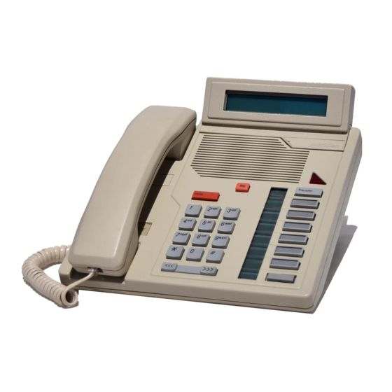
Introduction Physical characteristics Figure 3-1 shows the main components of the M5208. The set comes in three different colours: • Chameleon-grey (Engineering code NT4X41AA) • BTS light-grey (Engineering code NT4X41BA) • Black (Engineering code NT4X41CA) The Mean Time Between Failure (MTBF) for the M5208 is at least 100 years. -
Page 9: Chapter 2: Specifications
Telephone Equipment, CSA, DOC, UL, FCC (part 15 & part 68). Temperature In the Operating State, the M5208 temperature range is 0°C to 50°C (32°F to 122°F). In the Non-Operating State, the M5208 temperature range is -20°C to 70°C (-6°F to 158°F). -
Page 10: Vibration
Specifications Vibration The M5208 is designed to work to specifications after being subjected to the following vibrations in each of three orthogonal directions for 90 minutes: • Vibration frequency of 5 Hz to 500 Hz • Maximum half displacement 0.35mm (0.014 in) •... -
Page 11: Chapter 3: Operations And Features
Chapter 3 Operations and features Basic operations The M5208 Meridian Business Set can be used to make voice calls and operate selected DMS–10, DMS–100, or Meridian SL–100 features. All supported features can be accessed using keys provided on the M5208. For further details about software requirements, refer to NTP 297–2011–100 and... - Page 12 Operations and features ± The current drawn from the loop is 16 1mA when the set is active. The ± current drawn from the loop is 10 1mA when the set is inactive. 297–2011–213 02.01 Standard February 1999...
-
Page 13: Alphanumeric Display
Operations and features 3-3 Alphanumeric display The M5208 display screen allows access to the following features: Called Number Display/Called Name Display The display of the called number (or name of the party being called, when available) is always activated as dialing takes place. -
Page 14: Description Of Features
Operations and features Description of features The M5208 Business Set (see Figure 3-1) is characterized by the following: • there are 15 fixed keys with no LCD indicators: Release key (1), Hold key (1), volume key (1), dialpad keys (12) •... - Page 15 Operations and features 3-5 Table 3-1 Summary of M5208 keys and indicators Key or indicator Description Speaker Monitors the progress of a call without lifting the handset. Handset Used for talking on the phone—automatically selects the prime directory number when lifted.
-
Page 16: Basic Features
Warble tone sounds when the telephone is on-hook, 500 Hz local buzzer tone sounds when the telephone is off-hook and the associated LCD indicator flashes. Additional features In addition to the basic features, the M5208 has a 2 row by 24 character alphanumeric display. 297–2011–213 02.01 Standard February 1999... -
Page 17: Features Operation
The on-hook monitor volume level can be adjusted and automatically stored while monitoring. If the M5208 Business Set is disconnected from the line and then reconnected, all volume settings return to the original factory default values (Mid-point setting for alerting tones and minimum setting for on-hook monitoring). -
Page 18: Available Features
Operations and features Available features Feature key 1 is always assigned to the Prime Directory Number (PDN). If more than one Directory Number (DN) is available, additional feature keys can be assigned to these DNs progressing from feature key 1 to feature key 2 and so on. -
Page 19: Switch Generated Tone Characteristics
Operations and features 3-9 Switch generated tone characteristics The various tones heard on the M5208 are defined in Table 3-2. Table 3-2 Switch generated tones Tone Characteristic Ringing Interrupted warble tone, typically 2 seconds on, 4 seconds off. Busy Interrupted tone, 1 second on, 1 second off. -
Page 20: Chapter 4: Installation
Installation Installing the M5208 Before installing the M5208, check the package contents and cables, as described below. To install the M5208, follow procedure 4-1. If the M5208 needs to be mounted on the wall, follow procedure 4-2. Unpacking or packing Use proper care while unpacking any M5208 set. -
Page 21: Figure 4-1 M5208 Bottom View
Installation Procedure 4-1 How to install the M5208 Step Action Place the telephone in the work area (close to line cord connecting block/wall jack) upside down on soft, solid, and level work surface to prevent damage to movable keys and the telephone face. - Page 22 Installation 4-3 Procedure 4-1 How to install the M5208 (continued) Step Action Turn the telephone right side up and place it into its final position. Remove the number lens by inserting a paper clip end into the hole at the side and pop off the plastic lens. Print the directory number on the designation card and insert it into the lens recess.
-
Page 23: Wall Mounting The M5208
Your telephone set has been prepared at the factory for use on your desk. If you require the set to be positioned on a wall, follow procedure 4-2. Procedure 4-2 How to mount the M5208 on the wall Step Action... -
Page 24: Figure 4-3 M5208 Base Attachment
Installation 4-5 Procedure 4-2 How to mount the M5208 on the wall (continued) Step Action Reposition the wedge-shaped base (B) as shown in Figure 4- 3. Press the base firmly into the bottom of the set until the plastic tabs have clicked into place. -
Page 25: Figure 4-5 Final Wall Position
Installation Procedure 4-2 How to mount the M5208 on the wall (continued) Step Action Position the handset retainer (C) into the handset cradle, as shown in Figure 4-4. The handset retainer is included in the small package of plastic key caps which accompanies your telephone set. -
Page 26: Chapter 5: Verification Procedures
Chapter 5 Verification procedures Verification test routines This chapter describes M5208 maintenance and the following acceptance tests: • Loop check • Polarity check • Station Ringer test If the criteria outlined in the Line Engineering Rules, 297–2011–180, are observed, impulse or background noise and crosstalk compatibility problems are unlikely to occur. -
Page 27: Polarity Check
Verification procedures Polarity check The M5208 is polarity sensitive. If problems arise when the set is to be put into service, follow Procedure 5-1. Procedure 5-1 How to verify the polarity Step Action If the set does not respond (no dial tone) after 20 seconds, check polarity of the tip and ring leads (tip +, ring –). -
Page 28: Station Ringer Test
Verification procedures 5-3 Station Ringer test The Station Ringer test (SRT) tests the hardware of the M5208 Business Set and can be performed by the installer or repairman at the site with no involvement of Central Office personnel. No incoming calls can be received for the duration of a Station Ringer test. - Page 29 Verification procedures Procedure 5-2 How to perform the Station Ringer test Step Action or key/switch operated Response Messages Handset ON-hook. Press PDN All LCD’s ON LCD indicator ON key and dial STR (access code) using on-hook dialing. Note: All LCD indicators should be off before you start the test. access code. The 3-14 digit access code consists of a one to seven digit number (which is assigned by the telephone company according to local preferences) followed by the last two to seven digits of the PDN assigned to the telephone to be tested.
- Page 30 Verification procedures 5-5 Procedure 5-2 How to perform the Station Ringer test (continued) Step Action or key/switch operated Response Messages Feature key 4 LCD 4 ON Soft Reset, LCD ON Feature key 5 LCD 5 ON Soft Reset, LCD ON Feature key 6 LCD 6 ON Soft Reset, LCD ON...
- Page 31 Verification procedures Procedure 5-2 How to perform the Station Ringer test (continued) Step Action or key/switch operated Response Messages Vol DOWN Volume down None (Test Ring Volume control. HOLD key LCD 1–8 ON. 10/10 is Soft reset shown on the LCD display.
- Page 32 Verification procedures 5-7 Figure 5-1 Feature/line key and LCD assignments Key 8 Key 7 Key 6 Key 5 Key 4 Key 3 Key 2 PDN key Key 1 Feature/ Liquid Line Crystal Keys Displays Identification (LCDs) Identification 297–2011–213 02.01 Standard February 1999...
- Page 33 Verification procedures 297–2011–213 02.01 Standard February 1999...
-
Page 34: Chapter 6: Replacement Parts
Chapter 6 Replacement parts The M5208 has few field replaceable parts. The handset, handset cord, line cord equipped with Teladapt connectors, key lenses and labels can be changed. If a set fails to function properly, or if mechanical breakage occurs, do not attempt to effect repairs in the field. - Page 35 Engineering code Meridian M5208 Basic Business Set, B0242922 NT4X41GA Chameleon-grey, made in Australia (OZ TELSTRA) Meridian M5208 Basic Business Set, BTS B0242923 NT4X41HA light-grey, made in Australia (OZ TELSTRA) Meridian M5208 Basic Business Set, Black, B0242924 NT4X41JA made in Australia (OZ TELSTRA)
- Page 36 Nortel, the Nortel globemark, DMS-100, Meridian are trademarks of Northern Telecom. Information is subject to change without notice. Northern...
Need help?
Do you have a question about the M5208 and is the answer not in the manual?
Questions and answers