Nortel DMS-100 Series Product Manual
Distributed processing peripheral
Hide thumbs
Also See for DMS-100 Series:
- Replacement procedures (1100 pages) ,
- Maintenance manual (762 pages) ,
- Manual (543 pages)

Related Manuals for Nortel DMS-100 Series


Summary of Contents for Nortel DMS-100 Series
- Page 1 297-1001-019 DMS-100 Family Distributed Processing Peripheral Product Guide DPP001 and up Standard 02.01 April 1997...
- Page 3 DMS-100 Family Distributed Processing Peripheral (DPP) Product Guide Document Number: 297-1001-019 Product Release: DPP001 and up Document Release: Standard 02.01 Date: April 1997 Copyright Country of printing Legal statements Trademarks © 1993, 1997 Northern Telecom All rights reserved Printed in the United States of America Information is subject to change without notice.
- Page 4 Publication history Standard Issue 1.01 December 1993 • First standard issue. Standard Issue 2.01 April 1997 • DPP Hardware section is updated with information regarding the 3 1/2” 1-Gigabyte and 2-Gigabytes disk drives. • DPP cabinet dimension illustration in DPP Hardware section is corrected to show front view of entire chassis.
-
Page 5: Table Of Contents
Contents Understanding DPP ........1-1 DPP in the DMS network ......... . . 1-1 DPP System Architecture . - Page 6 iv Contents Finding DPP Information ....... 5-1 Administration ........... 5-1 Maintenance .
- Page 7 About this document When to use this document This document gives a general description of the Distributed Processing Peripheral (DPP). How to check the version and issue of this document The version and issue of the document are indicated by numbers, for example, 01.01.
- Page 8 References in this document The following documents are referred to in this document: • Distributed Processing Peripheral (DPP) Administration Guide, 297-1001-331. • Common Customer Data Schema, 297-1001-451. • Distributed Processing Peripheral (DPP) Hardware Component Replacement Guide, 297-1001-539. • Distributed Processing Peripheral (DPP) Quick Reference Guide, 297-1001-544.
-
Page 9: Understanding Dpp
Understanding DPP This chapter provides an introduction to the Distributed Processing Peripheral (DPP). DPP in the DMS network The DPP is a subassembly, mounted in the Input/Output Equipment (IOE) or Cabinetized IOE (CIOE) frame, with interfaces through four ports between the DMS Input/Output Controller (IOC) interface cards and the DPP interface cards. -
Page 10: Dpp System Architecture
1-2 Understanding DPP DPP System Architecture The architecture of the DPP is fully redundant (see Figure 1-2). Two functionally identical units linked by crossover circuits ensure that no critical AMA data is lost. Under normal operation, the active DPP unit writes identical copies of data to each of the hard-disk drive units. -
Page 11: Dpp System Architecture
Understanding DPP 1-3 Figure 1-2 DPP System Architecture Input/Output Distributed Processing Peripheral Equipment Host Office Data Stream Serial Data Stream Collector Interface Input/Output Interface Processor Controller Main Central Processing Disk Drive Modem Unit Unit A Input/Output Controller Meridian Data Stream Data Unit Interface Processor... - Page 12 1-4 Understanding DPP 297-1001-019 Standard 02.01 April 1997...
-
Page 13: Dpp Hardware
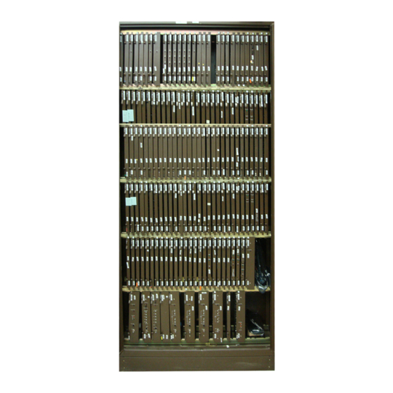
2-A0379820 DPP Hardware The following subsections describe the various hardware components for the DPP: • System description • Component description • Disk drive description • Switch and Status Panel description • Equipment list. System description Chassis organization The DPP consists of two processor units physically connected together. Figure 2-1 provides a view of the general appearance of the DPP. - Page 14 2-2 DPP Hardware Figure 2-1 Distributed Processing Peripheral Distributed Processing Peripheral Distributed Processing Peripheral Each DPP cabinet is approximately 24 inches (618 mm) high by 19 inches (483 mm) wide by 14 inches (362 mm) deep. Each unit, power supply, and disk drive is housed in a separate chassis.
-
Page 15: Dpp Cabinet Dimensions
DPP Hardware 2-3 Figure 2-2 DPP cabinet dimensions 17.52 in. (445 mm) Shipping 14.25 in. Bracket (362 mm) TOP VIEW 24.34 in. (618 mm) FRONT VIEW 19.00 in. (482.6 mm) DPP Product Guide DPP001 and up... - Page 16 2-4 DPP Hardware External connections to the DMS-100 are made through bulkhead connectors, terminal blocks, and ground studs provided on the sides of the cabinet as shown in Figures 2-3, 2-4, and 2-5. The bulkhead connectors are located as follows, when viewing the DPP unit from the rear: •...
-
Page 17: Data And Peripheral Interface Connectors - Turbo Dpps
DPP Hardware 2-5 Figure 2-3 Data and Peripheral Interface connectors - Turbo DPPs Not Used MMI Link 1 MMI Link 2 (Emergency Administrative Terminal) DSI0 (slot 13; A and B chassis) DSI1 (slot 12; A and B chassis) v.35 Link 1 (56K Baud maximum) v.35 Link 2 (56K Baud maximum) -
Page 18: Data And Peripheral Interface Connectors - Non-Turbo Dpps
2-6 DPP Hardware Figure 2-4 Data and Peripheral Interface connectors - Non-Turbo DPPs RS-232 Link (9600 Baud maximum) MMI Link 1 MMI Link 2 (Emergency Administrative Terminal) DSI1 (slot 13; A and B chassis) DSI0 (slot 12; A and B chassis) 297-1001-019 Standard 02.01 April 1997... -
Page 19: Power, Ground And Alarm Interface Connectors
DPP Hardware 2-7 Figure 2-5 Power, Ground and Alarm Interface connectors 8KHZ DC Input Power Alarms Clock (not supported, connector removed) Frame Ground 19 VAC Input (60 HZ Clock - not supported in systems with 3 1/2” disk drives) +12V Fuse (Terminal Block Chassis - no longer in production) Logic (Signal) Ground +12V AUX... - Page 20 2-8 DPP Hardware The DPP employs two complete processing units, one identified as the A chassis, the other as the B chassis. The A chassis is physically located above the B chassi two units being connected together as shown in Figure 2-6. The A chassis assembly contains the A processor and provides the switch and status panel for the system.
-
Page 21: Dpp Cabinet Subassemblies
DPP Hardware 2-9 Figure 2-6 DPP cabinet subassemblies Processor A Switch and Circuit Boards Status Panel A1-----------------------A14 Processor A chassis A20 Power Supply A21 Disk Drive A B20 Power Supply B21 Disk Drive B Processor B chassis B1------------------------B14 Rover Interface Processor B Panel Circuit Boards... -
Page 22: Connector And Pin Identification
2-10 DPP Hardware Connector and pin identification J Connectors: These connectors, located on certain subassemblies, are identified by the letter J, followed by up to three digits. For example, both the A and B chassis have J connectors on the pin side of the backplane; numbers increasing from right to left. -
Page 23: Circuit Assembly Racks
DPP Hardware 2-11 Circuit assembly racks Typical subassembly and circuit assembly locations are shown in Figure 2-7. The illustration shows that two PCA racks (A and B) are used. PCAs are designated A1 through A14 in the A (upper) chassis; B1 through B14 in the B (lower) chassis. - Page 24 B1 CPU LOGIC PCA A1 CPU LOGIC PCA B2 EPROM PCA A2 EPROM PCA B3 MEMORY EXPANSION PCA A3 MEMORY EXPANSION PCA B5 ERROR CONTROL II JUMPER PCA A5 ERROR CONTROL II PCA B6 QUAD SIO PCA A6 QUAD SIO PCA B7 56K INTERFACE PCA* A7 56K INTERFACE PCA* B11 DISK/SCSI INTERFACE PCA...
-
Page 25: Other Circuit Assembly Locations
DPP Hardware 2-13 Other circuit assembly locations Circuit assemblies are used in locations other than the card racks as described in the following paragraphs. There are PCAs located at the rear of the cabinet, on a hinged panel, as shown in Figure 2-8. -
Page 26: Auxiliary Circuit Assembly Locations
2-14 DPP Hardware Figure 2-8 Auxiliary circuit assembly locations Left rear of chassis (with cabinet back removed) Hinged card panel (closed) Power and Alarm Communications PCA (A16) or optional 56K Crossover PCA (B16) a. View with hinged card panel closed Disk/SCSI Crossover PCA (A15 and B15) (opposite side of hinged panel) -
Page 27: Disk Drives
DPP Hardware 2-15 The Disk Controller PCA is found on Non-Turbo DPP systems with 72- and 140-MB disk drives. The ribbon cables connecting the Disk Controller PCA to the disk drive unit are factory installed. DPP systems with 380- and 760 MB and 1- and 2-Gigabyte disk drives have integrated disk controllers. -
Page 28: Disk Drive Mounting Details (3 1/2" Disk Drives Shown)
2-16 DPP Hardware Figure 2-9 Disk drive mounting details (3 1/2” disk drives shown) Retainer Screw Extraction handle Rear Retainer Screw Top view Extraction handle Do not remove Retainer Front View screw Side View reference 297-1001-019 Standard 02.01 April 1997... -
Page 29: Dpp Disk Drive Assemblies (Front View)
DPP Hardware 2-17 Figure 2-10 DPP disk drive assemblies (front view) a. 72-Mbyte and 140-Mbyte Disk Drives b. 380-Mbyte and 760-Mbyte Disk Drives c. 1-Gbyte and 2-Gbyte Disk Drives DPP Product Guide DPP001 and up... -
Page 30: Switch And Status Panel/Rover Interface Panel
2-18 DPP Hardware Switch and status panel/rover interface panel This DPP option uses the upper Switch and Status Panel (A chassis) and the Rover Interface Panel (B chassis), which provide status information and manual controls, and Rover terminal interface. The Switch and Status Panel is built directly into the upper right portion of the A chassis. -
Page 31: Dpp Switch And Status Panel
DPP Hardware 2-19 Figure 2-11 DPP Switch and status panel Switch and Status Panel CRIT CHAS. GND. ROVER Interface Panel ROVER XMIT CHAS. GND. LEGEND: A Processor Status Lamps System Status Lamps ALM = Alarm CRIT = Critical = PRIME Mode MAJ = Major ONL = ONLY Mode MIN = Minor... -
Page 32: Switch And Status Panel Indicators
2-20 DPP Hardware The Switch and Status Panel provides switches for changing the operating condition of the A and B processors, alarm status indicators, and a banana jack connection to frame ground. The Rover Interface Panel provides a direct connection for the Rover maintenance terminal and a banana jack connection to frame ground. -
Page 33: Other Indicators
DPP Hardware 2-21 ONL (Only) Yellow status lamp (ONL) indicates which processor has sole, non- transferable operational control of the system. The other unit is not available for system functions in the event of a malfunction in the ONLY unit. Non- availability of a unit could be due to a fault in a unit or normal maintenance activity on a unit. -
Page 34: List Of Equipment Assemblies And Subassemblies
2-22 DPP Hardware List of equipment assemblies and subassemblies Table 2-2 lists the assemblies and subassemblies used in the DPP system. The list provides reference designations, abbreviated names, full names, part numbers, and usage notes, where applicable. Table 2-2 List of assemblies and subassemblies Reference ABBR Full name - part number - usage notes... - Page 35 DPP Hardware 2-23 Table 2-2 List of assemblies and subassemblies Reference ABBR Full name - part number - usage notes designator name EPROM Erasable, Programmable, Read-Only Memory PCA (1) NT6M63BF (MD) a. not compatible with 56K polling b. use with 72- or 140-Mbyte 5 1/4” disk drives (2) NT6M63CF (MD) a.
- Page 36 2-24 DPP Hardware Table 2-2 List of assemblies and subassemblies Reference ABBR Full name - part number - usage notes designator name QUAD Quad Serial Input/Output PCA (1) NT6M60AA (MD) - use for analog networks only (2) NT6M60BA - use for analog and digital networks 56K Interface PCA INTF (1) NT6M94AA...
- Page 37 DPP Hardware 2-25 Table 2-2 List of assemblies and subassemblies Reference ABBR Full name - part number - usage notes designator name SCSI SCSI Interface PCA - required for 56K/compression polling INTF (1) NT6M66BA - use with 380- and 760-Mbyte 5 1/4” disk drives (2) NT6M66BD - this PCA is no longer supported (3) NT6M66CA - use with 1- and 2-GByte 3 1/2”...
- Page 38 2-26 DPP Hardware Table 2-2 List of assemblies and subassemblies Reference ABBR Full name - part number - usage notes designator name DISK Disk II Crossover PCA - not compatible with 56K/compression polling; XOVR located on inner portion of hinged panel at rear of upper chassis (1) NT6M72AC (MD) - use with 72- and 140-Mbyte 5 1/4”...
- Page 39 DPP Hardware 2-27 Table 2-2 List of assemblies and subassemblies Reference ABBR Full name - part number - usage notes designator name 4-CHAN Four Channel Communication PCA - NT6M85AA a. Releases 01 and 02 PCA - use for analog networks only b.
- Page 40 2-28 DPP Hardware Table 2-2 List of assemblies and subassemblies Reference ABBR Full name - part number - usage notes designator name DISK Disk Drive Assembly (1) NT6M72AA a. 5 1/4” disk drive with a 72-Mbyte capacity b. includes disk controller PCA 680-9143 at location A21A1 c.
- Page 41 DPP Hardware 2-29 Table 2-2 List of assemblies and subassemblies Reference ABBR Full name - part number - usage notes designator name DISK Disk Drive Assembly (continued) (4) NT6M72DD a. 5 1/4” disk drive with a 380-Mbyte capacity b. use in a DPP system that has the 56K polling feature c.
- Page 42 2-30 DPP Hardware Table 2-2 List of assemblies and subassemblies Reference ABBR Full name - part number - usage notes designator name DISK Disk Drive Assembly (continued) (8) NT6M72HA a. 3 1/2” disk drive with a 2-Gbyte capacity b. use NT6M66CA SCSI Interface PCA and NT6M93BA SCSI Crossover PCA;...
- Page 43 DPP Hardware 2-31 Table 2-2 List of assemblies and subassemblies Reference ABBR Full name - part number - usage notes designator name EPROM Erasable, Programmable, Read-Only Memory PCA (continued) (4) NT6M63CJ a. compatible with 56K polling b. use with 380-Mbyte or 760-Mbyte 5 1/4” disk drives (5) NT6M63CL a.
- Page 44 2-32 DPP Hardware Table 2-2 List of assemblies and subassemblies Reference ABBR Full name - part number - usage notes designator name 56K Interface PCA INTF (1) NT6M94AA a. use with 380-Mbyte 5 1/4” disk drives when 56K polling is used b.
- Page 45 DPP Hardware 2-33 Table 2-2 List of assemblies and subassemblies Reference ABBR Full name - part number - usage notes designator name Data Stream Interface PCA (1) NT6M70AA (MD) (2) NT6M70CF (MD) (3) NT6M70AC Data Stream Interface PCA (1) NT6M70AA (MD) (2) NT6M70CF (MD) (3) NT6M70AC Bus Terminator PCA - NT6M68AA...
- Page 46 2-34 DPP Hardware Table 2-2 List of assemblies and subassemblies Reference ABBR Full name - part number - usage notes designator name SCSI SCSI Crossover PCA - located on inner portion of hinged panel at rear XOVR of upper chassis (1) NT6M93AA a.
- Page 47 DPP Hardware 2-35 Table 2-2 List of assemblies and subassemblies Reference ABBR Full name - part number - usage notes designator name DISK Disk Drive Assembly (1) NT6M72AA a. 5 1/4” disk drive with a 72-Mbyte capacity b. includes disk controller PCA 680-9143 at location A21A1 c.
- Page 48 2-36 DPP Hardware Table 2-2 List of assemblies and subassemblies Reference ABBR Full name - part number - usage notes designator name DISK Disk Drive Assembly (continued) (4) NT6M72DD a. 5 1/4” disk drive with a 380-Mbyte capacity b. use in a DPP system that has the 56K polling feature c.
- Page 49 DPP Hardware 2-37 Table 2-2 List of assemblies and subassemblies Reference ABBR Full name - part number - usage notes designator name DISK Disk Drive Assembly (continued) (8) NT6M72HA a. 3 1/2” disk drive with a 2-Gbyte capacity b. use NT6M66CA SCSI Interface PCA and NT6M93BA SCSI Crossover PCA;...
- Page 50 2-38 DPP Hardware 297-1001-019 Standard 02.01 April 1997...
-
Page 51: Dpp Software
DPP Software System description - software Overview The DPP is an intelligent peripheral of the DMS-100, capable of making decisions without guidance from the DMS-100 CC. The DPP activities are controlled by software resident in the DPP. The internal architecture of the DPP is closely related to the task structure of the software modules. -
Page 52: System Start-Up And Scheduler
3-2 DPP Software The basic boot programs search the disk for the larger programs, such as the application routines, and cause them to download to the DPP RAM. If good program/data cannot be found on disk, the boot program requests a program load from the DMS-100 through the DMS-100 to DPP human-machine interface links. -
Page 53: Interface Routines
DPP Software 3-3 required at the monitor level. Applications routines work directly with AMA data, reports, files, and formatting. Because applications are basically stand alone programs, they function independently with little or no intercommunication. The AMA application programs direct the processing of the call record data received from the DMS-100. -
Page 54: Disk Routines
3-4 DPP Software The DSI provides an active interface by emulating the MTD functions and providing two-way communication between the DPP and DMS-100. Disk routines The Disk Interface PCA has its own microprocessor and software routines. Read, write, and retry (error recovery) instructions are resident in the disk interface circuitry. -
Page 55: Dpp Communication
DPP Communication DPP-to-HOC communication Overview The HOC, located at a central collection point, uses a prearranged polling schedule for contacting the DPP and requesting transmission of data. Polling schedules are a function of the expected traffic at the various DPP sites. Data retrieval is accomplished in accordance with Bellcore X.25 (BX.25) level 3 protocol specifications. -
Page 56: Call Record Transfer (Polling)
4-2 DPP Communication Call record transfer (polling) After security has been established, call record transfer occurs via the following process: 1 The HOC sends a file poll command requesting a billing data file beginning with a particular sequence number. Unless there are less than one hundred primary blocks, one hundred primary blocks are sent in response to a pri- mary file poll request. -
Page 57: Polling Link Adjustment
DPP Communication 4-3 Polling link adjustment The DPP contains a feature that enables the user to perform maintenance-related functions on the data polling link. For actual maintenance conditions to be performed in response to a failed data link, refer to the DPP Maintenance Procedures Guide. - Page 58 4-4 DPP Communication 8 After the password exchange, the HOC initiates polling of the DPP for billing records. 9 After the transfer of billing records is complete, or if no HOC input buffer is available, or if a maximum polling volume is reached, the HOC ends the session by sending a Session Disconnect message to the DPP.
-
Page 59: Finding Dpp Information
Finding DPP Information Administration The manual, DPP Administration Guide (297-1001-331), describes how to perform the administrative tasks associated with a DPP. These tasks include: • accepting a newly installed DPP • maintaining the DPP load file • maintaining the DPP spare parts stock •... -
Page 60: Hardware Component Replacement
5-2 Finding DPP Information Hardware Component Replacement This manual gives a general description and replacement procedure for each hardware component, including circuit packs, power supplies and disk drives. It also describes option settings and provides an illustration for each circuit pack. -
Page 61: List Of Terms
List of terms List of terms Alternating Current Automatic Message Accounting An automatic recording system that documents all of the necessary billing data of subscriber-dialed toll calls. BELLCORE Bell Communications Research A group responsible for coordinating Bell Operating Company projects and setting requirements for telephone office equipment. - Page 62 6-2 List of terms Distributed Processing Peripheral A peripheral device of the DMS-100 that functions as an AMA data collector and an AMA transmitter in the AMATPS of the DMS-100. The DPP collects AMA data from the DIRP, formats the data, stores the data on its own internal disk and transmits the data to a data collection center when polled by the collection center.
- Page 63 List of terms 6-3 Host Office Collector An AMA data collection center that polls Central Offices (COs) in its region on a prescheduled basis and complies the collected data onto a magnetic tape. The tape is used by the Revenue Account Office for computing customer billing.
- Page 64 6-4 List of terms SCSI Small Computer System Interface Serial Input/Output Circuitry in the DPP that passes data from the DPP to external devices. The DPP employs four such circuits in its Quad SIO PCA that provides communications paths between the DPP and DMS-100/DPP maintenance interface, the DPP Emergency Administrative Terminal (EAT), and the remote polling center link.
- Page 65 Total pages in document = 20 Family Product Manual Contacts Copyright Legal statements Trademarks DocNum Application DocRelease Date Publishing statement...
-
Page 66: Distributed Processing Peripheral
DMS-100 Family Distributed Processing Peripheral Product Guide Information Services Northern Telecom PO Box 13010 Research Triangle Park, North Carolina 27709 Copyright © 1993, 1997 Northern Telecom All rights reserved Information is subject to change without notice. Northern Telecom reserves the right to make changes in design or components as progress in engineering and manufacturing may warrant.
Need help?
Do you have a question about the DMS-100 Series and is the answer not in the manual?
Questions and answers