Table of Contents
Advertisement
Quick Links
Advertisement
Table of Contents

Subscribe to Our Youtube Channel
Related Manuals for MICRO-EPSILON interferoMETER IMS5400-DS


Summary of Contents for MICRO-EPSILON interferoMETER IMS5400-DS
- Page 1 Quick Manual interferoMETER IMS5400-DS IMS5600-DS IMS5400-TH...
-
Page 2: Table Of Contents
Koenigbacher Str. 15 94496 Ortenburg / Germany Tel. +49 (0) 8542 / 168-0 Fax +49 (0) 8542 / 168-90 You can find further information about the measurement e-mail info@micro-epsilon.com system in the operating instructions. They are available at: www.micro-epsilon.com www.micro-epsilon.com/download/manuals/ man--interferoMETER-5x00--en.pdf... -
Page 3: General
General General Symbols used The following symbols are used in this document: CAUTION Indicates a hazardous situation which, if not avoided, may result in minor or moderate injury. NOTICE Indicates a situation that may result in property damage if not avoided. Indicates a user action. -
Page 4: Intended Use
General Intended Use - The interferoMETER measuring system is designed for use in an industrial environments and domestic areas. It is used for ƒ measuring displacement, distance, profile, thickness and surface inspection ƒ monitoring quality and checking dimensions. - The measuring system must only be operated within the limits specified in the technical data. - The measuring system must be used in such a way that no persons are endangered or machines and other material goods are damaged in the event of malfunction or total failure of the controller. -
Page 5: Glossary
Laser Safety Glossary Laser Safety The interferoMETER measuring system works with a = Measuring range pilot laser of a wavelength of 635 nm (visible / red) offering max. power of < 0.01 mW and a measuring SMR = Start of measuring range laser of a wavelength of 840 nm with a max. -
Page 6: Operating Modes
Operating Modes Operating Modes Setup, Connection Options Connect the components together and mount the The interferoMETER measuring system provides highly sensors into the clamps. accurate measurements of - distances against visually dense materials with Controller light-diffusing or reflective surfaces - thicknesses for transparent layer materials. By selecting the sensor, the distance or thickness mea- surement operating mode is selected. -
Page 7: Sensor Cable
Setup, Connection Options Sensor Cable General Rules As a matter of principle, avoid: Sensor and controller are connected through an - any contamination of the connector, e.g., dust or finger optical fiber. prints - Do not shorten or extend the optical fiber. - unnecessary mating cycles. -
Page 8: Pluggable Screw Terminals
Setup, Connection Options Pluggable Screw Terminals Description Comments 0 ... 5 V; 0 ... 10 V; R appr. 50 Ohm Analog Out Voltage output 5.5 V / 10.9 V with error, outside measuring range U/I out 4 ... 20 mA; R ≤... -
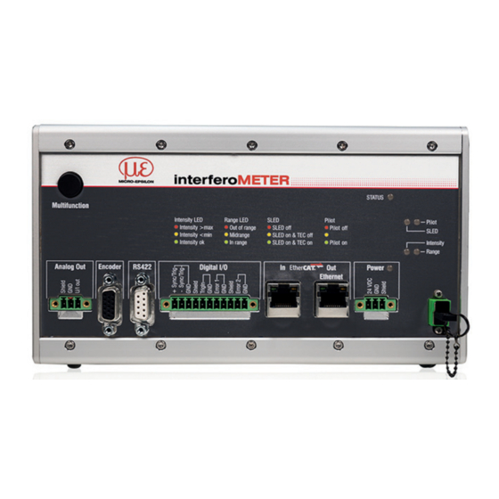
Page 9: Leds Controller
LEDs Controller LEDs Controller Power on Green Operating voltage available No error Status If EtherCAT is active, meaning of the LED is conform with the Ether-CAT guidelines. Signal in saturation Intensity Yellow Signal too low Green Signal ok No target object, or target object outside the measuring range Range Yellow Target close to mid of measuring range... -
Page 10: Button Multifunction
LEDs Controller Button Multifunction The Multifunction button of the controller has multiple functions. It enables, e.g., to operate the light source. The button is factory-set to the Pilotlaser on/off feature. Set / reset Starts or stops the master measurement of the selected signals master value Pilot laser Turns on/off the pilot laser... -
Page 11: Initial Operation
Operating range You can check the IP address of the controller, that are connected to a PC / network, with the sensorTOOL. exe program. This program is available online at https:// Working distance www.micro-epsilon.de/download/software/sensorTOOL. Thickness sensor exe. IMS5x00 Page 11... -
Page 12: Positioning The Target, Distance Measurement
Initial Operation Positioning the Target, Distance Measurement You can also position the sensor using the FFT sig- . The interferometric measuring principle provides The red-light pilot laser supports you in aligning the measurement values in front of and behind the actual sensor to the target during commissioning. -
Page 13: Positioning The Target, Thickness Measurement
Initial Operation Positioning the Target, Thickness Measurement Material Selection The red-light pilot laser supports you in aligning the To measure the thickness of a material, you must specify sensor to the target during commissioning. the material of the target. Change to Material selection, menu Settings > Turn on or off the pilot laser in the menu Settings >... -
Page 14: Measurement Configuration
Initial Operation Measurement Configuration Common measurement configurations (presets) for various target surfaces are stored on the controller and enable to quickly start the respective measurement task. This allows you to quickly start with your individual measurement task. In a preset the basic features like peak or material selection and calculation functions are already set. Go to the Home >... -
Page 15: Fft Signal Check
Initial Operation FFT Signal Check Go to the Measurement chart menu. Show FFT signal display with FFT. The signal in the chart window shows the distance be- tween sensor and target or the target thickness. Left 0 % (small distance) and right 100 % (large distance). -
Page 16: Distance And Thickness Measurement With Web Page Display
Distance and Thickness Measurement with Web Page Display Distance and Thickness Measurement with Web Page Display Align the sensor vertically to the target object. Then, move the sensor (or the target) closer, until you more or less reach the start of measuring range for your sensor. - Page 17 Distance and Thickness Measurement with Web Page Display Auto (= automatic scaling) or Manual The LED visualizes the status of the transmission of measured values: (= manual setting) allow for scaling the measure- - green: transmission of measured values is run- ment axis (Y axis) of the graphic.
-
Page 18: Data Output, Interface Selection
Data Output, Interface Selection Data Output, Interface Selection The controller supports - three digital interfaces that can be used in parallel for data output, ƒ Ethernet: enables fast data transfer, but provides no real-time capabilities (packet-based data transfer). Both measurement and FFT data can be transferred. -
Page 19: Set Ip Address
Save the new device settings. Click on Save set- ing parts, will be repaired or replaced free of charge, if tings. the device is returned to MICRO-EPSILON with shipping costs prepaid. Any damage that is caused by improper Service, Repair... - Page 20 MICRO-EPSILON MESSTECHNIK GmbH & Co. KG X9691389-A012090MSC Koenigbacher Str. 15 · 94496 Ortenburg / Germany Tel. +49 (0) 8542 / 168-0 · Fax +49 (0) 8542 / 168-90 MICRO-EPSILON MESSTECHNIK info@micro-epsilon.com · www.micro-epsilon.com *X9691385-A03* Your local contact: www.micro-epsilon.com/contact/worldwide/...
Need help?
Do you have a question about the interferoMETER IMS5400-DS and is the answer not in the manual?
Questions and answers