Table of Contents
Advertisement
Quick Links
Advertisement
Table of Contents

Related Manuals for MICRO-EPSILON optoNCDT ILR 1183


Summary of Contents for MICRO-EPSILON optoNCDT ILR 1183
- Page 1 Operating Instructions optoNCDT ILR 1183 ILR 1183-30 MICRO-EPSILON Eltrotec GmbH Manfred-Wörner-Straße 101 · 73037 Göppingen / Germany Tel. +49 (0) 7161 / 98872-300 · Fax +49 (0) 7161 / 98872-303 eltrotec@micro-epsilon.de · www.micro-epsilon.com...
- Page 2 MICRO-EPSILON Eltrotec GmbH Manfred-Wörner-Straße 101 73037 Göppingen / Germany Tel. +49 (0) 7161 / 98872-300 Fax +49 (0) 7161 / 98872-303 e-mail info@micro-epsilon.de www.micro-epsilon.com...
-
Page 3: Table Of Contents
5.4.4 Slave Address ..........................20 5.4.5 Bus Termination ..........................20 5.4.6 Baud Rate ............................. 20 5.4.7 Segment Length ........................... 20 5.4.8 Wiring Diagram ..........................21 SSI Interface ..............................22 Switching Outputs ............................23 Trigger Input ..............................25 optoNCDT ILR 1183... - Page 4 Switching Point Output 1 / 2 ......................40 8.2.11 Hysteresis Output 1 / 2 ......................... 40 8.2.12 Diagnostic Interval ........................41 8.2.13 Average ............................41 Malfunctions, Troubleshootings ....................42 Malfunctions ..............................42 Troubleshootings via Profibus ......................... 42 Cleaning ............................ 44 optoNCDT ILR 1183...
- Page 5 Liability for Material Defects ....................44 Service, Repair ......................... 45 Decommissioning, Disposal ....................45 Appendix Optional Accessory ........................46 Factory Settings ........................46 optoNCDT ILR 1183...
- Page 6 ILR 1183...
-
Page 7: Safety
Cable connectors must not be plugged or unplugged, as long as voltage is supplied. Remember to turn volt- age supply off before you begin working on cable connections. > Damage to or destruction of the sensor optoNCDT ILR 1183 Page 7... -
Page 8: Notes On Ce Marking
(EN) listed therein. The EU Declaration of Conformity is available to the responsible authorities according to EU Directive, article 10, at: MICRO-EPSILON Eltrotec GmbH Manfred-Wörner-Straße 101 73037 Göppingen / Germany The measuring system is designed for use in industrial environments and meets the requirements. optoNCDT ILR 1183 Page 8... -
Page 9: Intended Use
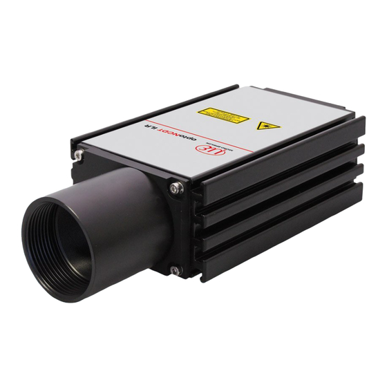
- Ambient pressure: atmospheric pressure Laser Class The optoNCDT ILR 1183 sensor operates with a wavelength of 650 nm (visible, red). The maximum optical output is ≤ 1 mW. The sensors are classified in Laser Class 2 (Class II). Class 2 (II) lasers are not notifiable and a laser protection officer is not required either. - Page 10 Although the laser output is low looking directly into the laser beam must be avoided. Due to the visible light beam eye protection is ensured by the natural blink reflex. Fig. 1 True reproduction of the sensor with its actual location of the warning labels optoNCDT ILR 1183 Page 10...
-
Page 11: Functional Principle, Technical Data
Functional Principle, Technical Data The optoNCDT ILR 1183 is a laser range finder to measure distances from 0.1 m to more than 150 m with inpoint accuracy. A given target can be clearly identified with the help of a red laser sighting point. In terms of operating reach, the optoNCDT ILR 1183 performs depending on the reflectance, morphology and qualities of the target to be measured. - Page 12 Beam diameter < 65 mm in 100 m distance Laser divergency 0.6 mrad Operating temperature -10 °C … +50 °C ( +14 °F ... to +122 °F) Storage temperature -20 °C … +70 °C (-4 °F ... to +58 °F) optoNCDT ILR 1183 Page 12...
- Page 13 Extruded aluminum profile with powder-coat paint finish Housing material 980 g Weight 1) Conditional on target reflectance, ambient light influences and atmospheric conditions 2) Statistic variation 95 % 3) Sensor settings occur about this interface. optoNCDT ILR 1183 Page 13...
-
Page 14: Delivery
Delivery Delivery Unpacking, Included in Delivery 1 Sensor optoNCDT ILR 1183-30 1 Instruction manual 1 CD with GSD file and operating instructions Optional accessories, separately packed: 1 Power supply-/output cable PC11xx with 3 m up to 30 m length (subject to order) -
Page 15: Installation
Installation Installation The sensor optoNCDT ILR 1183 is an optical sensor for measurements with millimeter accuracy. Make sure it is handled carefully when installing and operating. Sensor Mounting The sensor is be mounted by means of 4 screws type M6 DIN 934 and 2 groove stones in the installation slots. -
Page 16: Reflector Mounting
Move the sensor with the longest range to the reflector. Check the position of the light spot at the reflec- tor and set it if necessary. The light spot must always be in the centre of the reflector whatever the position. optoNCDT ILR 1183 Page 16... -
Page 17: Electrical Connections
The wiring of outputs with input signals can damage the Fig. 6 Connector on the rear side of the sensor sensor! The connectors are located on the rear side of the sensor. optoNCDT ILR 1183 Page 17... -
Page 18: Power Supply, Ssi-Interface
10 ... 30 VDC black n.c. violet ground grey/pink switching output 2 view on solder pin side, red/blue n.c. 12-pole female cable connector blue switching output 1 Fig. 7 Pin assignment for power supply and SSI interface optoNCDT ILR 1183 Page 18... -
Page 19: Profibus
The GSD file is named ILR809CB.GSD. It includes the two files “ILR1143.dib” and “ILR1143.bmp” which are necessary for representation of the sensor in the configuring tool. For information regarding integration of these files, please consult the special documentation parts that relate to the configuring tool. optoNCDT ILR 1183 Page 19... -
Page 20: Slave Address
Use cable of type A for cabling in accordance with these segmenting limits. This cable type provides the fol- lowing characteristics: - Surge impedance 135 ... 165 OhmW - Capacitance per unit length ≤ 30 pf/m optoNCDT ILR 1183 Page 20... -
Page 21: Wiring Diagram
- Wire diameter > 0.64 mm - Wire cross-section > 0.34 mm² 5.4.8 Wiring Diagram Profibus IN Pin 2 Pin 4 Pin 2 violet Pin 4 Profibus OUT supply Fig. 8 Minimum wiring configuration of Profibus interface optoNCDT ILR 1183 Page 21... -
Page 22: Ssi Interface
A desired measuring mode can be selected via the Profibus. The SSI interface works independently of the Profibus interface. For SSI interface operation, the wiring diagram is as follows: optoNCDT ILR 1183 Page 22... -
Page 23: Switching Outputs
ƒ With increasing distance, the output switches from LOW to HIGH, as soon as AC + AH/2 is exceeded, ƒ with decreasing distance, it switches from HIGH to LOW, as soon the distance value falls below AC – AH/2. optoNCDT ILR 1183 Page 23... - Page 24 - ExtUserPrmData = 35 “Hysteresis output 2 (31-16)” for AH alarm hysteresis 2 - ExtUserPrmData = 36 “Hysteresis output 2 (15-0)” for AH alarm hysteresis 2 Further switching functionalities, for example, monitoring for specified operating ranges may be accom- plished by combining the two switching outputs. optoNCDT ILR 1183 Page 24...
-
Page 25: Trigger Input
(0 ... Off, 1 ... On) must be turned on. Parameter settings for Trigger Input can be made with the help of the Profibus Master, using the Encoder profile and Class 2 encoder functionality. optoNCDT ILR 1183 Page 25... - Page 26 - 0 V < LOW < 6.5 V Wiring connections for working with the trigger input are as follows: application Profibus IN Pin 2 Pin 4 green TRIG Pin 2 Pin 4 violet Profibus OUT supply Fig. 12 Wiring of trigger input optoNCDT ILR 1183 Page 26...
-
Page 27: Operation
Fig. 13 Measurement against a reflector optoNCDT ILR 1183 Page 27... -
Page 28: Profibus Interface
Slave Address Setting Slave address 4 is factory-set. Changes can be made via the Profibus Master. A desired address can be assigned using the SSA (Set Slave Address) signal. optoNCDT ILR 1183 Page 28... -
Page 29: Selection Of Operating Mode
Octets in a telegram are arranged in a Profibus-compliant manner (big endian), that means, the MSB always comes first and the LSB is always the last one. Octet Type Output 1…4 signed 32 position data from encoder optoNCDT ILR 1183 Page 29... -
Page 30: Cyclical Data Exchange - Output (Master -> Slave)
M will be calculated in such a manner that the following equation is met: Preset Offset Preset Laser offset The new offset value can be read in the diagnostic data as Octet 30 ... 33. optoNCDT ILR 1183 Page 30... -
Page 31: Parameter Data
(profibus default) bool unused bool class 2 functionality on/off bool commissioning diagnostic on/off bool commissioning diagnostic on/off bool reserved for future use bool reserved for future use bool reserved for manufacturer bool reserved for manufacturer optoNCDT ILR 1183 Page 31... - Page 32 Since the sensor is a linear encoder that measures absolute distances, the four parameters - “code sequence” - ”scaling function control“ - ”Measuring units per revolution“ - ”Measuring range in measuring units“ will be ignored. optoNCDT ILR 1183 Page 32...
-
Page 33: Diagnostic Data
32 single turn resolution => 100000 nm = 0.1 mm 15 ... 16 unsigned 16 no. of distinguishable revolutions – unused (=0) class 2 diagnostic bool E98 – Timeout SIO bool E99 – unknown error optoNCDT ILR 1183 Page 33... - Page 34 40 ... 43 unsigned 32 unsigned 32 measuring units per revolution – unused (=0) 44 ... 47 unsigned 32 unsigned 32 measuring range – unused (=0) 48 ... 57 10 byte 10 byte serial number optoNCDT ILR 1183 Page 34...
- Page 35 Since the sensor is a linear encoder that measures absolute distances, the four parameters - “code sequence”, - ”scaling function control“, - ”measuring units per revolution“ - ”measuring range in measuring units“ will be ignored. optoNCDT ILR 1183 Page 35...
-
Page 36: Control Commands
The DW mode uses a steady measuring rate of 10 Hz. A white target board is a necessary prerequisite for measured values to be stable. There must be no sharp jumps in distance above a value of 16 cm within the area being measured. optoNCDT ILR 1183 Page 36... -
Page 37: Dx - Distance Tracking With Cooperative Target (50 Hz)
SSI interface terminal be activated. 8.2.1 Class 2 Function Selects slave type according to Encoder profile. 8.2.2 Extended Diagnostics Transmits more than six standard diagnostic bytes (16 bytes as Class 1 Slave, 61 bytes as Class 2 Slave). optoNCDT ILR 1183 Page 37... -
Page 38: Scale Factor
The parameter Trigger Delay sets the time from the arrival of a trigger pulse to the actual beginning of mea- surement. It may correspond to any value between 0 and 9999 msec. Factory setting: Trigger delay = 0. optoNCDT ILR 1183 Page 38... -
Page 39: Error Reaction
In addition, by varying the Measuring time, one may also configure the measuring frequency. This may prove helpful where data volumes have to be restricted. The following provides an approximated measuring time equation: Measuring time » Measuring Time × 240 ms (> 0) Factory setting: Measuring time = 0. optoNCDT ILR 1183 Page 39... -
Page 40: Display Offset
HIGH Negative hysteresis LOW HIGH HIGH HIGH Dist. Dist. Fig. 16 Behavior of digital switching output for positive and negative hysteresis Factory setting: Hysteresis output 1 = 100. Factory setting: Hysteresis output 2 = 100. optoNCDT ILR 1183 Page 40... -
Page 41: Diagnostic Interval
Example with N = 7: 2+3+4+5+6+7+8 ..0 1 2 3 4 5 6 7 8 gets to Average value n 3+4+5+6+7+8+9 ..1 2 3 4 5 6 7 8 9 gets to Average value n +1 optoNCDT ILR 1183 Page 41... -
Page 42: Malfunctions, Troubleshootings
1. straylight (steady light), make sure that neither target not entry open- 2. hardware error ing of sensor is exposed to light from reflecting surfaces, projectors or sun 2. Service required > reship for repair optoNCDT ILR 1183 Page 42... - Page 43 SIO overflow Check time of emitted signals in application software, inte- grate delay on transmission if necessary Framing-Error SIO Reship sensor for repair Contact technical support Hardware error Reship sensor for repair Contact technical support optoNCDT ILR 1183 Page 43...
-
Page 44: Cleaning
Within this period, defective parts, except for wearing parts, will be repaired or replaced free of charge, if the device is returned to MICRO-EPSILON Eltrotec with shipping costs prepaid. Any damage that is caused by improper handling, the use of force or by repairs or modifications by third parties is not covered by the liabil- ity for material defects. -
Page 45: Service, Repair
Incorrect disposal may cause harm to the environment. Dispose of the device, its components and accessories, as well as the packaging materials in compli- ance with the applicable country-specific waste treatment and disposal regulations of the region of use. optoNCDT ILR 1183 Page 45... -
Page 46: Appendix
Appendix | Optional Accessory Appendix Optional Accessory PC1100-3/RS232 Power supply- /Output cable-RS232, length 3 m PBC1100-I/O-5 Profibus In-Out-cable, length 5 m PBC1100-I-5 Profibus In-cable, length 5 m PBC1100-I-10 Profibus In-cable, length 10 m PBC1100-O-5 Profibus Out-cable, length 5 m PBC1100-O-10 Profibus Out-cable, length 10 m PBFC1100 Profibus female connector... - Page 48 MICRO-EPSILON Eltrotec GmbH X9751185-A051069SWE Manfred-Wörner-Straße 101 · 73037 Göppingen / Germany MICRO-EPSILON Eltrotec Tel. +49 (0) 7161 / 98872-300 · Fax +49 (0) 7161 / 98872-303 *X9751185-A05* eltrotec@micro-epsilon.de · www.micro-epsilon.com...
Need help?
Do you have a question about the optoNCDT ILR 1183 and is the answer not in the manual?
Questions and answers