
Related Manuals for LINET Image 3 B


Summary of Contents for LINET Image 3 B
- Page 1 Instructions for Use and Technical Description Image 3 B Bariatric hospital bed for acute care D9U001AM2-0101 Version: 06 Publication Date: 2020-03...
- Page 2 Manufacturer: LINET spol. s r. o. Želevčice 5 274 01 Slaný Czech Republic Tel.: +420 312 576 111 Fax: +420 312 522 668 E-mail: info@linet.cz http://www.linet.cz Service department: service@linetgroup.com Image 3 B Bariatric hospital bed for acute care Author: LINET, s.r.o.
-
Page 3: Table Of Contents
16.3 Modes of Cleaning and Disinfection ......47 5 Product Description .............18 17 Troubleshooting ............48 5.1 Image 3 B (1AM2) - Single Collapsible Siderails and Powder 18 Maintenance ...............49 Coated Head Board and Foot Board ........ 18 18.1 Regular maintenance ..........49 6 Technical Specification ..........19... -
Page 4: Symbols And Definitions
1 Symbols and Definitions 1.1 Warning Notices 1.1.1 Types of Warning Notices Warning notices are differentiated by the type of danger using the following key words: ► CAUTION warns about the risk of material damage. ► WARNING warns about the risk of physical injury. ►... -
Page 5: Symbols On The Package
1.4 Symbols on the Package FRAGILE, HANDLE WITH CARE THIS WAY UP KEEP DRY (PROTECT FROM HUMIDITY) PAPER RECYCLING SYMBOL DO NOT USE HAND TRUCK HERE DO NOT STACK DURING STORAGE D9U001AM2-0101_06... -
Page 6: Symbols And Labels On The Bed
1.5 Symbols and Labels on the Bed READ INSTRUCTIONS FOR USE WARNING THERMAL PROTECTION OF TRANSFORMER ONLY SUITABLE FOR INDOOR USE PROTECTION AGAINST ACCIDENTS DUE TO ELECTRICAL CURRENT – TYPE B APPLIED PARTS SAFETY ISOLATING TRANSFORMER, GENERAL CE MARK OF CONFORMITY WITH EU REGULATION JACK FOR ATTACHMENT OF CONDUCTOR FOR POTENTIAL EQUALISATION SAFE WORKING LOAD WARNING AGAINST CRUSHING OR TRAPPING... - Page 7 USE MATTRESS RECOMMENDED BY MANUFACTURER WEIGHT OF BED DO NOT PUT ANY OBJECTS HERE WEEE SYMBOL (RECYCLE AS ELECTRONIC WASTE, DO NOT PUT INTO THE HOUSEHOLD WASTE) MEDICAL DEVICE (COMPATIBLE WITH MEDICAL DEVICE REGULATION) RECYCLING SYMBOL DO NOT POLLUTE THE ENVIRONMENT MANUFACTURER MANUFACTURING DATE REFERENCE NUMBER (PRODUCT TYPE DEPENDING ON CONFIGURATION)
- Page 8 GO BUTTON (PRESS TO ACTIVATE CONTROL ELEMENT) STOP BUTTON (PRESS TO INTERRUPT BED POSITIONING) HEAD BOARD UNLOCKED OR FOOT BOARD UNLOCKED (POWDER COATED HEAD BOARD AND FOOT BOARD) HEAD BOARD LOCKED OR FOOT BOARD LOCKED (POWDER COATED HEAD BOARD AND FOOT BOARD) D9U001AM2-0101_06...
-
Page 9: Serial Label With Udi
(01) 8592654234365 2020-03-10 (11) 200310 CUC: 000008 (21) 20200127689 Fig. Serial Label with UDI (Image 3 B) Address of Manufacturer Manufacturing Date (Year-Month-Day) DI (Device Identifier) / GTIN (Global Trade Item Number) 1D Bar code GS1-128 (Serial Number) Symbols Configuration number... -
Page 10: Visual Signalisation
1.8 Visual signalisation 1.8.1 Mains Power LED (Attendant Control Panel) MAINS POWER LED MEANING connected to the mains flashing: 0,6s lit / 0,6s not lit keyboard error (flashing inverted to Lock LED) error (first fault) flashing: 0,1s lit / 0,1s not lit service mode not lit disconnected from the mains power transformer switching error 1.8.2 Accumulator Indicator (Attendant Control Panel) ACCUMULATOR INDICATOR MEANING... -
Page 11: Night Bed Illumination
1.9 Night Bed Illumination It is possible to equip Image 3 B with undercarriage illumination. The lightning helps the patient or hospital personnel to better ori- entate in room with lowered or turned off light. The lowered intensity of lightning is set up after turning the bed on. -
Page 12: Definitions
1.10 Definitions Basic Bed Configuration the pricelist model configuration, not including a mattress Bed Weight The value depends on the product configuration, accessories or customer adjustments. Clearance of Undercarriage the height from the floor to the lowest point of the undercarriage between the castors, for the manipulation of accessories under a braked bed in the standard position Duty Cycle... -
Page 13: Abbreviations
1.11 Abbreviations AC ( ~ ) Alternating Current Attendant Control Panel European Conformity Cardiopulmonary Resuscitation Sound Intensity Unit DC ( Direct Current Configuration number Electromagnetic Compatibility Field-effect transistor High Frequency High Pressure Laminate Hardware Intensive Care Unit INT. Duty Cycle Ingress Protection Intravenous Light Emitting Diodes... -
Page 14: Safety Instructions
2 Safety Instructions WARNING! Image 3 B bed should be left in its lowest position when the patient is unattended in order to reduce risk of injury due to falls! WARNING! Siderails of Image 3 B should be located in the „up“ position to reduce the risk of the patient accidentally... - Page 15 WARNING! An additional MULTIPLE SOCKET-OUTLET or extension cord shall not be connected to the MEDICAL ELECTRICAL SYSTEM. WARNING! During specific investigations or treatments the significant risks of reciprocal interference posed by ME equip- ment may occur. DANGER! Risk of injury or death due to use of incorrect equipment! ► Always conduct the risk assessments required for the selection of suitable equipment. WARNING! Any serious incident that has occurred in relation to the device should be reported to the manufacturer and the competent authority of the Member State in which the user and/or patient is established! WARNING! Only authorised and trained person using the tool is allowed to change fuses and power supplies!
- Page 16 ► Follow the instructions for use carefully. ► Any non-observance of this manual may lead to injuries or material damage. ► Exclusively use the bed if it is in perfect working order. ► If necessary, check the bed functions daily or at each shift change. ►...
-
Page 17: Intended Use
LINET®’s efforts in research, design and manufacture ensure LINET® products are of the highest quality and fit for their intended purpose. However, LINET® can take no responsibility for any damage to the products or any harm to patients, staff or other individuals resulting from: ►... -
Page 18: Product Description
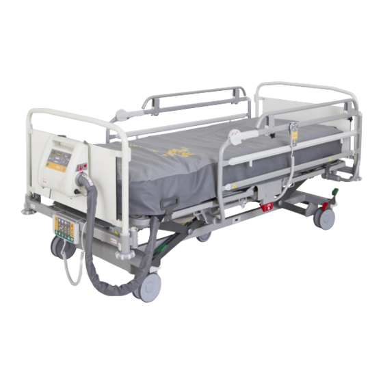
CPR control lever – backrest release Accessories rail Fifth castor Calfrest handle / Mattress holder Housing for the Protector® Foot board unlocking mechanism Attendant Control Panel Protective bumper NOTE For safe, easy handling, LINET® recommends that two technicians put the bed into service. D9U001AM2-0101_06... -
Page 19: Technical Specification
6 Technical Specification 6.1 Applied parts type B All the accesories the patient can reach are type B applied parts. List of type B applied parts: ► ACP Attendant Control Panel ► Handset ► Satellite controller ► Siderails ► Head board and foot board ►... -
Page 20: Electrical Specifications
2x T1.6A L 250 V for 230 V version / 2x T3.15A L 250 V for 100-127 V version NOTE Upon request, LINET® can deliver hospital beds with electrical specifications that comply with regional standards (custom voltage, different mains plugs). -
Page 21: Manufacturer Instructions - Electromagnetic Emissions
6.5.1 Manufacturer instructions - electromagnetic emissions Emission Test Compliance RF emissions Group 1 CISPR 11 RF emissions Class B CISPR 11 Harmonic emissions Class A IEC 61000-3-2 Voltage fluctuations / flicker emissions Complies IEC 61000-3-3 6.5.2 Manufacturer instructions - electromagnetic susceptibility Immunity Tests Compliance level Electrostatic discharge (ESD) -
Page 22: Use And Storage Conditions
Table 1 - IMMUNITY to RF wireless communications equipment Test frequency (MHz) Band (MHz) Service Modulation Immunity Test Level 380 - 390 TETRA 400 Pulse modulation 18 Hz 430 - 470 GMRS 460, FRS 460 FM ± 5 kHz deviation 1 kHz sine 704 - 787 LTE band 13, 17... -
Page 23: Scope Of Delivery And Bed Variants
The bed is delivered with deactivated accumulator. To activate accumulator see chapter “Accumulator activation”. 8.2 Bed Variants 8.2.1 Standard version: Image 3 B Model 1AM2 Features – Image 3 B Model 1AM2 (model no. see product label): ■ Mattress Support Platform □... -
Page 24: Putting Into Service
9 Putting into Service WARNING! Risk of injury when working on the bed! ► Ensure that the bed is disconnected from the mains connection prior to putting into service, putting out of service and maintenance. ► Ensure that the castors are locked prior to putting into service, putting out of service and maintenance. CAUTION! Material damage due to incorrect putting into service! ►... -
Page 25: Accumulator Activation
9.1 Accumulator Activation 9.1.1 Placement of Control Section 9.1.2 Removing the Isolating Foil PULL 9.1.3 Isolating Foil Check if isolating foil is complete and undamaged as shown: If isolating foil is damaged, contact the manufacturer’s service department immediately. NOTE: It is recommended to wear gloves when removing the isolating foil. D9U001AM2-0101_06... -
Page 26: Head Board And Foot Board
9.2 Head Board and Foot Board WARNING! Risk of injury when inserting the head board and foot board! ► To insert head board and foot board into corner posts, hold them by the corner handles on top with both hands. ►... -
Page 27: Powder Coated Head Board And Foot Board
9.2.2 Powder coated head board and foot board Fig. Unlocked position Fig. Locked position Unlocked (the head board or foot board can be removed) Locked (head board or foot board is locked) Manipulation with head board and foot board Insert the head board or foot board as follows: ►... -
Page 28: Mattress Support Platform
9.3 Mattress support platform The mattress support platform consists of removable plastic sections. Fig. Mattress support platform To remove/install sections of the mattress platform: ► Pull out mattress support platform sections. ► Install mattress support platform section. ► The correct fi tting of section is signalized by hearable “click”. ►... -
Page 29: Potential Equalisation
9.4 Potential Equalisation The bed is equipped with a standard protective connector. This connector is used for potential equalisation between the bed and any intravascular or intracardiac device connected to the patient to protect the patient from static electric shocks. Fig. -
Page 30: Before Use
9.5 Before Use CAUTION! Material damage due to temperature difference! ► If there is a considerable temperature difference between the bed and the place of operation (after transport/storage), leave bed unconnected for 24 hours to allow the temperature to equalise. Prepare the bed for service as follows: ►... -
Page 31: Power Supply Cord (Mains Power Cable)
10 Power Supply Cord (Mains Power Cable) CAUTION! Disconnecting bed from the mains does not stop motions of the bed! ► Stop the bed before disconnection bed from the mains. Attachment plug is means of connecting and disconnecting bed from the mains. Power supply cable (mains power cable) must be attached with a hook at the head end of the bed during transport. -
Page 32: Status Faulty Accumulator
The LED indicates the accumulator charge status: Yellow LED Accumulator charge status Not lit Accumulator capacity is sufficient (charging completed) Short flashing (short, intermittent illumination) Accumulator is charging - continue charging until the LED is (circa 1.8 sec.) extinguished. In emergency cases, the accumulator can be used as a backup power source for a short period. -
Page 33: Deactivating The Accumulator
11.4 Deactivating the Accumulator To avoid damaging the bed and the environment during storage: ► Deactivate the accumulator on the Attendant Control Panel. To deactivate the accumulator on the Attendant Control Panel: ► Disconnect the bed from the mains. ► Disconnect the ground wire. -
Page 34: Acp - Attendant Control Panel (Nurse Controller)
12.1 ACP – Attendant Control Panel (nurse controller) Attendant Control Panel is main control panel of the bed. Nurse controller can be placed in the shelf. We recommend placing ACP panel on the head board or foot board or hold it in the hands while controlling the bed. Fig. -
Page 35: Central Stop Button
12.1.1 Central STOP Button The central STOP button 7 immediately interrupts all bed movements. Pressing central STOP button 7 for at least 0.3 seconds immediately stops all electronic bed movements. 12.1.2 Activating GO Button The GO button 18 activates the keypads on all control elements except the foot control. A GO button is included on a number of different control elements. - Page 36 To set the programmed positions: ► Activate the keypad by pressing the GO button. ► Press and hold corresponding function button until the desired position is reached. Trendelenburg Position (13) The Trendelenburg position serves as an anti-shock position. All parts of the mattress platform are flattened. Mattress platform tilts head down.
-
Page 37: Handset
If required, prevent the patient from adjusting the bed as follows: ► Disable functions. ► Unplug handset (if the bed is equipped with Plug and Play). NOTE: The handset can be plugged into another LINET® hospital bed with the Plug and Play slot. D9U001AM2-0101_06... -
Page 38: Cpr Backrest Release
12.3 CPR backrest release WARNING! Risk of injury due to lowering the backrest too quickly! ► Ensure single collapsible siderails are in their lowest position or ensure split plastic siderails are in their highest position. ► Ensure there are no body parts between siderails and backrest. ►... -
Page 39: Siderails
12.4 Siderails The single collapsible siderails are components of the bed. The siderails cannot be dismounted. Hospital personnel are responsible for locking siderails in the highest position when the patient is on the bed. To fold the siderail down: ► Take hold of the release mechanism and push the siderail towards the head of the bed to unlock the locking system 1. -
Page 40: Equipment
13.3 Brake Signal – Signalization of Unbraked Bed It is possible to equip Image 3 B with signalization of unbraked bed. The signalization of unbraked bed signalizes, that bed is co- nnected to the mains but is not braked. This status is signalized by acoustic signal. To shut down acoustic signal brake the bed or unplug bed from the mains. -
Page 41: Accessories
Risk of injury due to damaged accessories! ► Use exclusively accessories in perfect condition. NOTE: The manufacturer assumes no responsibility for the use of accessories not approved by the manufacturer. NOTE: All accessories conform to EN 60601-2-52:2010. The following accessories are suitable for the Image 3 B: ■ Lifting pole □ powder-coated □... -
Page 42: Lifting Pole
Insert the lifting pole into both housings at the corners at the head of the bed with the help of a second person ► Ensure that both safety pins are locked into place NOTE: The date of manufacture is marked on the grab handle. LINET® recommends replacing the plastic grab handle every four years. 15.2 Infusion Stands... -
Page 43: Siderails Extension - Extender
Fig. Installing the Extender® on the siderail Fig. Inserting the screw Fig. Securing the Extender® Fig. Image 3 B with installed Extender® Install the Extender® as follows: ► Place the Extender® on the upper edge of the siderail. Siderails must be in the upper position. -
Page 44: Image 3 B Protector
15.4 Image 3 B Protector® WARNING! Risk of injury due to patient falling out of bed! ► Ensure the Protector® is securely anchored to the housing. ► To check stability, push the Protector up without touching the release button. ►... -
Page 45: Cleaning/Disinfection
16 Cleaning/Disinfection WARNING! Risk of injury when working on the bed! ► Prior to assembly, disassembly, cleaning and maintenance, ensure that all adjustment functions are locked. ► Ensure the bed is disconnected from the mains during cleaning process. ► Pay extra attention when cleaning any movable or controlling mechanisms of the bed to prevent involuntary activation, entrapping or crushing. -
Page 46: Safety Instructions For Cleaning And Disinfection Of The Bed
16.1 Safety Instructions for Cleaning and Disinfection of the Bed Preparation for cleaning: ► Drive the bed on a place where the cleaning process will be performed and then brake the bed. ► Position the mattress platform to its highest positions and also position the backrest and thighrest parts so the back side of those parts are accessible for cleaning. -
Page 47: Modes Of Cleaning And Disinfection
16.3 Modes of Cleaning and Disinfection Part of bed – Image 3 B Daily C&D Changing patient C&D Complete C&D Single collapsible siderails (stickers) Head board and Foot board (stickers) Controllers (cables) ... -
Page 48: Troubleshooting
17 Troubleshooting DANGER! Danger to life due to electric shock! ► If a fault occurs ensure the electric motor, power box and other electrical parts checked by qualified personnel only. ► Do not open protective covers of the electric motor or power box. Error/Fault Cause Solution... -
Page 49: Maintenance
Ensure that maintenance is performed exclusively by manufacturer´s customer service or by authorised service personnel certified by the manufacturer. ► If the defect cannot be repaired, do not use the bed. LINET ® recommends attaching the maintenance plaque to the bed. 18.1 Regular maintenance ► Check regularly movable parts for wear. -
Page 50: Disposal
Based on the Directive No. 2002/96/ EC (Directive WEEE - Waste, Electric and Electronic Equipments) the company LINET, s. r. o. is registered in the List of Electric and Electronic Equipment Producers (Seznam výrobců elektrozařízení) on the Ministry of the Environment of the Czech Republic... -
Page 51: Warranty
20 Warranty LINET® will only be held responsible for the safety and reliability of products that are regularly serviced and used in accordance with the safety guidelines. Should a serious defect arise that cannot be repaired during maintenance: ► Do not continue to use the bed.
Need help?
Do you have a question about the Image 3 B and is the answer not in the manual?
Questions and answers