
Subscribe to Our Youtube Channel
Related Manuals for LINET Gracie


Summary of Contents for LINET Gracie
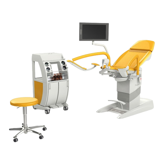
- Page 1 Gynaecological examination chair Gracie Digital videocolposcope UN-PACKING MANUAL INSTRUCTION MANUAL D9U001GKB-0101 Version: 03 Publication Date: 2024-02...
- Page 2 274 01 Slaný Tel.: +420 312 576 111 Fax: +420 312 522 668 E-mail: info@linet.cz http://www.linet.com Service department: service@linetgroup.com Authorized Representative in Great Britain: LINET UK Ltd 11 Brunel Way Segensworth East Fareham Hampshire PO15 5TX United Kingdom Authorized Representative in Switzerland:...
- Page 3 GYNAECOLOGICAL EXAMINATION CHAIR GRACIE DIGITAL VIDEOCOLPOSCOPE Author: L I N E T spol. s r.o. Related links: http://www.linet.com D9U001GKB-0101 Version: 03 Date of publication: 2024-02 Copyright © L I N E T spol. s r.o., 2024 Translation © L I N E T spol. s r.o., 2024...
- Page 4 Please read carefully all these operating instructions that have been elaborated to familiarize you with the proper use and the respective parameters of a prototype gynecological chair (hereinafter referred to as Gracie). Please always follow these instructions and always use the chair only in accordance with these instructions.
- Page 5 Pictogram Meaning Warning Warning: Dangerous electric voltage This symbol introduces any information, that may help you to avoid operative problems Type B applied parts Marking of intermittent operation, i.e. if the product has been continuously operated for time period “x”, then it must rest idle for time period “y”. For int x/y example int 10 / 20 means that after 10 minutes of continuous use /positioning the product must be out of use/not positioned for 20 minutes...
- Page 6 Pictogram Meaning Transportation marking: “Air pressure”. Marking according to the directive EC 2002/96/EC (Directive about the disposal of old electric and electronic appliances). Symbol for: “Do not dispose of the product into communal waste. Use special collection points for old electronic appliances.“...
- Page 7 Abbreviation Meaning Catalogue number Light emitting diodes Power intake units Computer standard for computer imaging technology Universal serial bus Liquid crystal display Information technology Personal computer Sound intensity unit Pressure unit ČSN Protected marking of the Czech technical norms Frequency unit in the SI system The Service Message Block is a protocol for sharing files in Microsoft Windows networks.
- Page 8 Data plate with UDI The serial label contains information about Address of Manufacturer, Manufacturing Date (Year-Month-Day), Product Reference Number, Product Serial Number, Global Trade Item Number (GTIN), Unique Device Identification (UDI), symbols, weight specifications and electrical specifications. If you have any queries, please, contact the producer – L I N E T spol. s r.o., or local sales representatives.
-
Page 9: Table Of Contents
Connection of the GRACIE chair to a PC/MAC (GKB-AX) ....... 66 Initial steps ...................... 67 Direct connection of the GRACIE chair to the doctor's PC/MAC using WLAN . 68 Direct connection of the GRACIE chair to an existing WLAN network in the office ....................... - Page 10 5.7.2 Synchronization of date and time - "Date & time" ........109 5.7.3 Photo and video timestamp settings - "Photo timestamp" ....... 110 5.7.4 Setting the information ‟Zoom level in photo“ .......... 110 5.7.5 Setting the information ‟Zoom level on screen“ ........111 5.7.6 Revision number ..................
- Page 11 Enviroment protection ..................149 Disposal ......................149 9.1.1 Within Europe ..................149 9.1.2 Outside Europe ..................150 D9U001GKB-0101 11/150...
-
Page 12: Un-Packing Manual
1 Un-packing manual Cut the securing tape. Remove the top lid and the box ring. Cut and crush the corners of the lower enclosure so we can take the chair easily off the pallet. 12/150 D9U001GKB-0101... - Page 13 Gradually remove all accessories from the buffer, including the manual controller and the network cable. Destroy the empty buffers. D9U001GKB-0101 13/150...
- Page 14 Using tools, screw off the doctor´s chair from the palette so that the upper area of the palette is free. 14/150 D9U001GKB-0101...
- Page 15 Dismount the 4 securing screws M8 on the auxiliary frame. Push the rear part of the chair over the palette forward. Screw on the castors. The castors must be screwed on so that the braked castors are on one side all the time.
- Page 16 Move the chair so that only a short part of the frame is on the palette – approximately 4 cm. Stop the castor which is on the ground. 16/150 D9U001GKB-0101...
- Page 17 Screw on the remaining castors (castors with brake must be on one side of the chair), release the braked castor and move the chair out of the palette. D9U001GKB-0101 17/150...
- Page 18 When tilting the chair, it is necessary to underlay part of the foot support with a soft pad so that no damages to the chair occur. When reaching the place of destination, brake one side, tilt the chair over this side and remove the castors and 4 screws M10 fixing the supporting frame to the chair underframe.
- Page 19 Before tilting back, connect the backup battery to the control box according to the following procedure. Ensure the power cable is unplugged of power site! 1) Tilt the armchair and support the leg from the side (see Fig. 1). 2) On the bottom side of the base there is a disconnected supply connector (highlighted in Fig.
- Page 20 Mounting the arm with the monitor Dismantle the top plastic cover of the column. Pull the arm cables through the column hole. Use three screws to attach the arm to the column. Secure the screws with Loctite243. Plug the connectors and cables (connectors are not interchangeable). 20/150 D9U001GKB-0101...
- Page 21 Fasten the plugged connectors and cables with electrical strips 2x left monitor (red arrow) or 4x right monitor (all arrows) Then close the upper plastic cover of the column and screw it on. D9U001GKB-0101 21/150...
-
Page 22: General Information
2 General information Standards This product meets the requirements of current standards ČSN EN 60601- 1:2007, ČSN EN 60601-1-1 ed.2:2001, ČSN EN 60601-2-52:2010, ČSN EN 60601-1-2 ed.2:2008. According to the directive 93/42/ES of the Council of Medical Devices, as amended, the chair is classified as class I medical device. General Instructions The chair operation is only permitted in areas that meet the conditions of current standards for electric distribution in places intended for medical purposes. - Page 23 Gynecological chair GRACIE • The chair Gracie serves for gynecological examination and ultrasound scan of patients, resp. for small ambulatory operations. For hygienic reasons, it is necessary for the upholstery to always be covered before the chair is used. The product does not contain latex.
-
Page 24: Electrical Safety And Emc
Electrical safety and EMC • Since the unit is powered from the network, it may cause interference with sensitive equipment due to generation of electromagnetic field. In order to reduce the influence of undesired electromagnetic effects, the chair was designed in compliance with ČSN EN 60601–1-2. To prevent the occurrence of these problems the chair must be used in compliance with this manual. - Page 25 • Portable and mobile HF communication devices should not be used closer than the recommended distance of d = 15 cm from any part of the chair, including the cables. • The gynaecological chair, colposcope and monitor must be installed operated accordance with...
-
Page 26: Intended Use
Intended use The chair serves for gynecological examination and ultrasound scan, resp. for small ambulatory operations. Part of the chair can be accessories – digital video colposcope and LCD monitor. Colposcope is used in gynecological examinations to provide enlarged, non- contact visualization of the female external genitalia (vulva, vagina, vaginal portion of cervix) and anus. -
Page 27: Setting-Up The Chair
Setting-up the Chair The chair Gracie shall be set up by the representatives of L I N E T spol. s r.o. Any handling/maneuvers with the chair within the room is permitted according to the instructions stated in the Section “4”. - Page 28 the network for more than one week, it is necessary to disconnect the battery connector from the CB (Control box). 28/150 D9U001GKB-0101...
- Page 29 In case of uneven surface under the chair a safety switch is switched on to stop the movement of the chair. This condition is indicated by a red diode on the chair base (Fig. 1). To remedy the colliding condition the chair feet must be screwed in so that the chair base is closer to the floor.
-
Page 30: Summary
Integrated video colposcope Video colposcope LED illumination Two light intensities of the video colposcope Integrated polarization filter WLAN/LAN connection of the chair to a PC HDMI IN/OUT VGA IN Ethernet cable * part of standard equipment of the GRACIE chair 30/150 D9U001GKB-0101... -
Page 31: Color Versions
Overview 1 Chair base Head part with cushion 2 Integrated wheels Goepel leg holders 3 Mobile foot control Paper tray under the cushion 4 Fixed foot control Back part with cushion 5 Hand control Seat part with cushion 6 Chair lifting column Leg holders with thigh support 7 Hand control holder Video colposcope... -
Page 32: Chair Operator
4 Chair Operator The chair can be operated only by trained personnel. Training is conducted by the manufacturer’s expert representatives. Motorized Adjustments (foot controller) Relevance of the foot control buttons is evident in the picture. For motor set up the requested function button needs to be pushed down and held. After pushing requested button, the light coloured parts move. - Page 33 At the top there is placed a panel with colour indicator lamps. The lit letter A, B or C means of the attending doctor´s option. Furthermore here is a green indicator lamp indicating the connection of the chair to the network, an orange indicator lamp indicating the connection of wireless control to the chair.
- Page 34 Battery All versions of a gynaecologic chair are equipped with a backup battery. This battery makes possible to set the chair in case of a power cut, or unavailability of supply from the electric power network. In the case of fully charged battery, 3 display fields lit, with decreasing capacity the individual fields switch off.
-
Page 35: Motorized Adjustments (Remote Control)
Motorized Adjustments (Remote control) Height adjustment loading areas (up and down) Back rest tilting with footrest at same time (The back part down and footrest up / the back part up and footrest down) Foot rest tilting (up and down) Examination position (memory function) Position for getting on and out (a memory function) -
Page 36: Motorized Adjustments (Mobile Foot Controller)
Motorized Adjustments (Mobile Foot Controller) The wireless foot controller provides remote radio transmission of a command for activation of the Gracie memory functions related to the positions for getting on, examination, and ultrasound scan. The remote control transmitter is powered by two alkaline batteries of LR14 type, C size, voltage 1.5 V. The mobile wireless foot controller signal range is 5 m from the transmitter located in the chair base. - Page 37 Controlling the position for getting on and out, position for examination and position of the bed for ultrasound examination: Position examination Indicating mobile foot controller Position for getting on and out Position ultrasound examination Manipulation To start the chair moving the corresponding button of the foot control needs to be stepped on shortly.
- Page 38 For erasing, please hold the pairing button (use a non-conductive object for this operation) on the GRACIE chair up to the LED indicator turn off. 38/150...
- Page 39 Error Messages Error messages are indicated by means of a LED located on the mobile foot controller. When operating the device, the following situations can occur: After pressing the button, the battery Almost discharged battery symbol will flash In case you will not use the wireless foot control for longer period, remove batteries from the control.
-
Page 40: Memory Functions
Memory Functions Mobile foot control and part of the hand control are equipped with buttons (so called memory functions) to set up the positions for getting on, examination and ultrasound. After pushing on the button the chair automatically goes to the selected position set in advance. In case of using the memory function, please, pay enhanced attention when the chair is setting up itself for certain time –... -
Page 41: Manipulating The Chair
Manipulating the chair 4.5.1 Using integrated wheels It is essential that the chair travels without any person sitting in it. Manipulation wheel is used only for chair travel within a room for the purposes of cleaning the area under the chair, setting up the chair in the room, etc. Sticking the manipulation wheels out 1) Drive the chair up from its lowest position (c. -
Page 42: Without Integrated Wheels
Sliding the manipulation wheels in 1) Drive the chair up (watch electric cables under the base) 2) The wheels automatically hide and the base is inclined to the original position. The signal for secure sliding the wheels in and setting up the base is an audible click together with the sliding out of the button for sticking the manipulation wheels out. -
Page 43: Not Permitted Manipulation
4.5.3 Not permitted manipulation Do not push or lean on arm of monitor. Pinching Points When adjusting the foot rests, there is a danger of pinching the body under the seat. Thus, it is forbidden to place any part of the leg in areas indicated by a red circle as in Fig. -
Page 44: Synchronous Adjustment Of Foot Rests
The place where an accessory can be attached on the flange by screws. If the chair is adjusted to the boarding position (downward movement), objects may be pinched between the chassis cover and the column cover. Therefore, it is forbidden to place any objects on the chassis cover. Synchronous Adjustment of Foot Rests •... - Page 45 screw adjusting rigidity of the foot rests D9U001GKB-0101 45/150...
-
Page 46: Paper Roll Replacement
Paper Roll Replacement To replace the paper roll, tilt the upholstery of the backrest. Paper roll width is 39 cm. Paper from a roll can be drawn through the upper gap (point A), the back part and sitting part will be covered, or through the lower gap (point B), only the sitting part will be covered. -
Page 47: Heating Of Seat Section
Heating of seat section The sitting part can be equipped with heating as accessory equipment. Its Scale of control is only on the left side of the sitting part. heating Switch for Switch Switch for lower temperature heater temperature increase Seat heating serves to increase the patient's comfort during the examination. -
Page 48: Antishock Position
If the ambient temperature falls below 0° C the seat heating is disabled (does not work). The heating function is active again if the seat is placed in an environment with ambient temperatures above 0° C. When the sun or other external source of heat heats up the seat may activate thermal fuse that disconnect the heating. -
Page 49: The Socket-Outlet Panel
4.11 The socket-outlet panel If a warning is placed on the cover plate, there are no connectors under the cover. The cover may only be replaced by an authorized and trained worker using tools. Notice: After uninstalling the cover, you can access the connectors, but the liquid ingress protection (IP) drops to IPX0 (shown by the sticker). -
Page 50: Equipotential Terminal
Protective device After connecting cabling, the mains plugs must be secured by protective equipment. Protective device 4.12 Equipotential terminal It is a component of each version of the chair. It is used for connecting with other apparatuses in the examination room to equalize electrostatic tension. Equipotential terminal 50/150... -
Page 51: Full Hd Gkb - Screen
5) Turn on displaying the image from the external input of the video converter (ultrasound). For return without saving select ‘exit’. • If only one external device (ultrasound) is connected to the GRACIE chair, pressing of the appropriate button on the control keyboard on the screen will display its image on the screen, regardless of whether HDMI or VGA input is used (the converter is able to identify it). -
Page 52: Operating The Monitor
4.13.1 Operating the monitor Basic functions of the monitor, such as brightness, contrast, RGB and reset of factory setting can be set in the menu. To access the menu, press on the control panel of the monitor. Active source Inactive source Brightness Contrast RGB settings... -
Page 53: Image From The Video Colposcope
When both diodes start flashing slowly, the system is ready for use and the video colposcope can be switched on. Icon in the lower right corner informs whether the GRACIE chair is connected to the doctor's PC. The chair is not connected to the The chair is connected to the PC. -
Page 54: Image From External Input (Ultrasound)
4.13.3 Image from external input (ultrasound) Remove rubber covers on the rear side of the chair base. Then it is possible to connect an external device using input located on the socket terminal on the rear side of the chair base (VGA input, HDMI input). After the chair is connected to power supply, initialization of the system starts. -
Page 55: Connection Of External Screen In The Office
4.13.4 Connection of external screen in the office Remove rubber covers on the rear side of the chair base. Then connect external TV via HDMI cable to the GRACIE chair (HDMI OUT output). If image from the video colposcope is displayed on the screen, image from the video colposcope is displayed also on the external screen connected via HDMI output. - Page 56 Positioning The screen can be tilted horizontally by 0 to 15 . Height adjustment of the screen is not possible. The arm with the screen moves along with the chassis of the gynaecological chair. The screen can be tilted on the joint in the arm in the range from – 55 to + 55 56/150 D9U001GKB-0101...
-
Page 57: Digital Videocolposcope
Maintenance and cleaning • A regular yearly inspection of this medical equipment must be carried out. Maintenance of the screen • Disconnect the screen and chair from power supply before cleaning. This will prevent accidental pressing of buttons on the control panel. •... -
Page 58: Summary Of Basic Parts
4.14.1 Summary of basic parts Video colposcope Camera with LED diodes Video colposcope body Video colposcope handle with control panel Control panel Polarization filter control knob Section of the video colposcope arm Switch of input from the video colposcope or ultrasound 17"... -
Page 59: Setting Up The Video Colposcope
The first option of setting up is in the case when video colposcope is in the passive (parking position). As evident in picture No. 1, the video colposcope is found under the seat of the Gracie examination chair. In such position the colposcope is turned off. In this position the colposcope does not create any space for pinching. - Page 60 Procedure when removing the video colposcope from passive to active position is evident in the pictures The colposcope is Gripping The colposcope is in parked position handle, we pull the in active position. under the seat. colposcope from under the seat out. •...
- Page 61 In such case the safeguard, which is placed under the seat of the chair, is activated. In case of collision it will prevent from footrest's further moving and this will prevent from permanent damage of video colposcope or shoulder of video colposcope by automatic switching off the move of the chair.
-
Page 62: Colposcope Control Panel
4.14.3 Colposcope control panel Diode indicating Switching switching light colposcope on / off – Short press sleeping Long press – switching the system Manual focusing In case of switched- on system, the green LED is on Zooming, distancing picture. When Function for storing the pictures (short zooming,... - Page 63 Colposcope function Colposcope is turned on by short press of left button in upper row. The turned-on colposcope is indicated by a green diode located right from the on/off button. Colposcope sleeping (passive mode) is then activated by repressing the same button. If we want to turn the colposcope completely off, we press the button long.
- Page 64 LED diode lights up, indicating recording of a video sequence. Pressing the button with camera icon again stops the recording and the video sequence is stored into the memory of the GRACIE chair. Data are stored in ".jpg" (photos) and ".avi" (video) formats.
-
Page 65: Maintenance And Cleaning
4.14.4 Maintenance and cleaning • A regular yearly inspection of this medical equipment must be carried out . • For a clear picture, the lens of the video colposcope should be wiped regularly with a microfibre wipes. Maintenance of the videocolposcope •... -
Page 66: Connection Of The Gracie Chair To A Pc/Mac (Gkb-Ax)
• You are recommended to backup your data (photos and videos) before every firmware update. Updating the firmware will cause their deletion! • Do not connect two or more GRACIE chairs at the same time. Always perform the installation one by one. -
Page 67: Initial Steps
Initial steps • Turn on the doctor's PC/MAC. • The PC/MAC must have a WLAN module, otherwise you will have to use a USB WLAN adapter or connect the chair using Ethernet cable. Switching the connection type on the video colposcope The video colposcope is set to WLAN transmission in default. -
Page 68: Direct Connection Of The Gracie Chair To The Doctor's Pc/Mac Using Wlan
If you are using this type of connection, you will not be able to use WLAN for connection to the Internet on your PC/MAC. WLAN in your PC/MAC is able to receive only one signal - in this case from the GRACIE chair. 68/150... - Page 69 1) Connect the unpacked and correctly set-up chair to power supply. 2) After approximately one or two minutes the GRACIE chair will start to send WLAN signal, i.e. will create its own WLAN network. 3) Turn on your PC/MAC. Your PC/MAC must be equipped with an active WLAN module, otherwise it will not be possible to set up a wireless connection between the GRACIE chair and the PC/MAC.
- Page 70 GRACIE chair and not to the Internet. MS - WINDOWS APPLE OS-X 10) Now the GRACIE chair is wirelessly connected to the doctor's PC/MAC. To set up a storage folder, refer to Section "5.6 Connecting a network folder…" 70/150...
-
Page 71: Direct Connection Of The Gracie Chair To An Existing Wlan Network In The Office
Direct connection of the GRACIE chair to an existing WLAN network in the office D9U001GKB-0101 71/150... - Page 72 3) Press ENTER on the keyboard of your PC/MAC or click on "Go" on the address bar. 4) You will enter the settings page of the WLAN module of the GRACIE chair. Verification of connection may take from two to three minutes. It depends on the operation system of your PC/MAC.
- Page 73 5) You will be promoted to enter the username and password. Username: admin Password: linet After entering the username and password, press OK. Your will enter the WLAN/LAN connection menu of the GRACIE chair. MS - WINDOWS APPLE OS-X Passwords and accesses have been factory pre-set. It is recommended to change them, refer to Section 5.8...
- Page 74 6) Go to the following path //c-XXXXXXXXXXX and click on "Wireless client" (see below in red) and type the name of the existing WLAN network in the office/hospital into the ESSID box (see below in blue). In this case the name of the network is "marketing".
- Page 75 8) Clicking on Save and apply will save the changes. 9) After saving the changes, the GRACIE chair will automatically connect to the selected WLAN network. For correct functioning of the connection it is necessary to connect the PC/MAC to the particular wireless network, in this case "marketing".
-
Page 76: Direct Wired Connection Of The Gracie Chair To The Doctor's Pc/Mac
Direct wired connection of the GRACIE chair to the doctor's PC/MAC 76/150 D9U001GKB-0101... - Page 77 + and - FOCUS buttons. Hold the buttons until an orange diode of the camera button lights up on the video colposcope. After pressing the buttons, static IP address and subnet mask will be automatically set in the GRACIE chair as follows: 10.0.0.1 / 255.255.255.0 D9U001GKB-0101 77/150...
- Page 78 1) First, you need to set correct values in your PC/MAC. Open the „Network & Internet settings“ MS - WINDOWS "Open Network Preferences" APPLE OS-X 78/150 D9U001GKB-0101...
- Page 79 2) Click on "Change adapter settings" (see below). MS - WINDOWS Choose the Ethernet adapter through which your MAC is connected to the GRACIE chair. APPLE OS-X D9U001GKB-0101 79/150...
- Page 80 Choose "Local Area Connection". MS - WINDOWS "Configure IPv4" and "Manually" APPLE OS-X 80/150 D9U001GKB-0101...
- Page 81 3) Choose "Local Area Connection". Right click on the icon and select "Properties". 4) Select "Internet Protocol Version 4 (TCP/IPv4)" in the "Networking" tab and click on "Properties". D9U001GKB-0101 81/150...
- Page 82 5) Type the values below into the table. Then click on OK. Now you are connected to the GRACIE chair using direct Ethernet cable connection. 82/150 D9U001GKB-0101...
-
Page 83: Connection Of The Gracie Chair To The Doctor's Pc/Mac Using An Existing Network Connection
Connection of the GRACIE chair to the doctor's PC/MAC using an existing network connection The chair must be temporarily connected to the PC/MAC either using WLAN (Chapter 5.2) or directly using a cable (see Section 5.4). D9U001GKB-0101 83/150... -
Page 84: Activation Of Wired Connection To An Existing Network
3) Press ENTER on the keyboard of your PC/MAC or click on "Go" on the address bar. 4) You will enter the settings page of WLAN module of the GRACIE chair. Verification of connection may take from two to three minutes. It depends on the operation system of your PC/MAC. - Page 85 Username: admin Password: linet After entering the username and password, press OK / LOG IN. Your will enter the WLAN/LAN connection menu of the GRACIE chair. MS - WINDOWS APPLE OS-X Passwords and accesses have been factory pre-set. It is recommended to change them, refer to Section 5.8...
- Page 86 6) Click on "Ethernet (wired)" (see below in red) and select "DHCP (automatic)". 7) Now you need to save the changes by clicking on "Save and apply" in the bottom part of the screen. 8) After saving the changes, the GRACIE chair will automatically switch to wired connection mode. 86/150...
- Page 87 9) Then you need to set correct values in your PC/MAC. Open the „Network & Internet settings“ "Open Network Preferences" APPLE OS-X D9U001GKB-0101 87/150...
- Page 88 "Change adapter settings" (see below). MS - WINDOWS Choose the Ethernet adapter through which your MAC is connected to the GRACIE chair. APPLE OS-X 88/150 D9U001GKB-0101...
- Page 89 11) Choose "Local Area Connection". Right click on the icon and select "Properties". MS - WINDOWS Select "Internet Protocol Version 4 (TCP/IPv4)" in the "Networking" tab and click on "Properties". D9U001GKB-0101 89/150...
- Page 90 "Configure IPv4" and "Using DHCP" and press Apply to confirm. 90/150 D9U001GKB-0101...
- Page 91 12) Select "Obtain an IP address automatically" in the table. Then click on 15) After clicking OK, the GRACIE chair will be connected to your PC/MAC. D9U001GKB-0101 91/150...
-
Page 92: Connecting A Network Folder, Placing A Folder On The Desktop, Saving Images Into A Shared Network Folder
Connecting a network folder, placing a folder on the desktop, saving images into a shared network folder 1) After successful pairing of the GRACIE chair with your PC/MAC, you need to connect the folder where photos and videos taken from the video colposcope of the GRACIE chair are stored. - Page 93 IP address (10.0.0.1) of the GRACIE chair into the address bar MS - WINDOWS 4) Press ENTER on the keyboard of your PC/MAC or click on "Go" on the address bar. 5) You will be promoted to enter the username and password.
- Page 94 7) Click on "c-XXXXXXXXXXX" in the address bar. MS - WINDOWS 8) The folder "data" will now be displayed. MS - WINDOWS 94/150 D9U001GKB-0101...
- Page 95 9) You can place a shortcut of this folder on your desktop. Right click on the folder "data" and select "Create shortcut". 10) Shortcut of the folder "data" will be created on the desktop of your PC/MAC. D9U001GKB-0101 95/150...
- Page 96 You can also share a folder using the function "Map Network drive". 1) Right click on the folder "data" and select "Map Network drive". MS - WINDOWS 2) Then select a drive, for example Z: (or other available drive) and confirm by pressing "Finish".
- Page 97 3) When you open„This PC“, network folder "data ) (Z:)“ will (\\c-XXXXXXXXXXX be visible. The image shows the remaining storage space in the GRACIE chair. MS - WINDOWS • The memory is automatically erased when limit values are reached (6.5 GB) so that you are able to continue taking new photos and videos.
- Page 98 Saving copies of images into a shared folder in the doctor's computer (PC/MAC). These settings can be used if it is necessary to save a copy of an image into a specific folder in the computer for easier communication with the patient data management software.
- Page 99 Fill in the fields: 2) Upload path – Network address in the format "//IP address/folder name " E.g. //10.0.0.124/shared IP address = network address of the computer into which you are going to save the images. Here is how to find out the IP address of the doctor's computer in WiFi AP connection mode.
- Page 100 folder name = name of your shared folder. Right-click on the folder you want to share. In this case the name of the folder is "shared". Click on "Share with" and "Specific people". Select the user (your account), click on the user and then click on "Share". 100/150 D9U001GKB-0101...
- Page 101 The folder is now shared. Confirm by clicking on "Done". Now click on "Properties" of the folder. Then click on " Sharing" and "Advanced sharing" and "OK". D9U001GKB-0101 101/150...
- Page 102 Click on "Share this folder", "Certifications", "Add", "Advanced", "Find". Select the user (your account), click on the user and then click on "OK". 102/150 D9U001GKB-0101...
- Page 103 Confirm again with "OK", select Change and Read in Permissions. Confirm with "OK" twice. The folder is now shared and its name can now be typed into the Upload path. D9U001GKB-0101 103/150...
- Page 104 3) Domain – if the computer is connected into a network domain, the domain name must be filled in. If the computer is connected into a workgroup, it must not be filled-in. How to find out the network domain: Right-click on "Computer"...
- Page 105 4) Username, Password – name and password of the user who has the right to write into the shared folder. Saving into a folder accessible for everyone is not allowed 5) Enable the saving function – Enabled button 6) Click on "Save and apply". 7) Logfile (file upload.txt) serves for your network administrator in case more detailed information is needed.
-
Page 106: General Settings
//c-XXXXXXXXXXX.local in the address bar, where XXXXXXXXXXX is the serial number on the nameplate of the Gracie chair or type IP address (10.0.0.1) of the GRACIE chair into the address bar MS - WINDOWS When typing the path into the address bar, make sure to use correct... - Page 107 3) Press ENTER on the keyboard of your PC/MAC or click on "Go" on the address bar. 4) You will be promoted to enter the username and password. Your will enter the WLAN/LAN connection menu of the GRACIE chair. Username: admin Password: linet...
-
Page 108: Directory View Settings - "Data Directory Structure
2) If you want to store data from the video colposcope of the GRACIE chair in directories with day names, click on "One directory per day". -
Page 109: Synchronization Of Date And Time - "Date & Time
Menu also offers optional storing the photos in a specific format. Click on ‟File name “and select the menu item. The explanation of abbreviations can be seen on the right side. Confirm the selection by clicking on SAVE AND APPLY 5.7.2 Synchronization of date and time - "Date &... -
Page 110: Photo And Video Timestamp Settings - "Photo Timestamp
To finish the changes click SAVE AND APPLY. 5.7.3 Photo and video timestamp settings - "Photo timestamp" Click "Yes" in the menu if you want to save information about the exact time of taking the photo or video. Otherwise click on "No". To finish the changes click SAVE AND APPLY. -
Page 111: Setting The Information "Zoom Level On Screen
Setting the information ‟Zoom level on screen“ 5.7.5 Go to Menu and click on ‟Yes“, if you want to display zoom level on screen during the examination. Zoom levels response to your zooming in/out. If you do not want to display this information, click on „No“. Press SAVE AND APPLY to confirm completion of the change 5.7.6 Revision number... -
Page 112: Time Setup,,Clock On Screen
Time setup,,Clock on screen“ 5.7.7 Go to the menu and click „Yes“ if you want to see the time on the screen . If not click „No“. Click on the button so that you can ,,Synchronize with your time“ Click on the button SAVE AND APPLY to save it. 112/150 D9U001GKB-0101... -
Page 113: Changing Default Passwords
Changing default passwords 1) After successful pairing of the GRACIE chair with your PC/MAC, you need to connect the folder where photos and videos taken from the video colposcope of the GRACIE chair are stored 2) Open the Internet browser... - Page 114 4) Press ENTER on the keyboard of your PC/MAC or click on "Go" on the address bar. 5) You will be promoted to enter the username and password. You will enter the settings page of WLAN module of the GRACIE chair.. Username: admin Password: linet...
- Page 115 To change the default password protecting your photos and videos against access of unauthorized persons change the current password linet to a new one. 5) To change the default password protecting the access to the menu of the microcomputer of the GRACIE chair change the current password linet to a new one.
-
Page 116: Accessories
6 Accessories Compulsory accessories Video colposcope with polarisation filter (GKB-512) Video colposcope is provided with a reflection reduction system. The system is based on the technique of polarisation decreasing considerably the extent of reflections occurring in the fall of light on the device, e.g. mucus, gynaecological mirror or other surfaces. - Page 117 PHOTO WITHOUT FILTER PHOTO WITH FILTER It is recommended that automatic focusing (see Section 3.14) is activated again after the function for removal of reflections has been used. It is achieved by focusing the camera on the surfaces located under the layer reflecting light.
-
Page 118: Standard Leg Supports (Gkb-201.X)
Standard leg supports (GKB-201.X) Non-sectional leg supports are included in the basic product price. Standard leg supports with a lamp integrated in the left leg support (GKB-202.X) The leg supports are identical to the standard ones, but the left leg has a lamp built into it, which helps in illuminating the working area. -
Page 119: Sectional Leg Supports (Gkb-205.X)
Sectional leg supports (GKB-205.X) Sectional leg supports allow their removal and make it easier especially for immobile patients to mount the chair. Removal procedure: 1) Push the securing wire in the direction away from the chair (figure 1) 2) Lift the support by ca 30°and pull it out of the arm joint (figure 2) Fig. -
Page 120: Sectional Leg Supports With A Lamp Integrated In The Left Leg Support (Gkb-206.X)
Sectional leg supports with a lamp integrated in the left leg support (GKB-206.X) The sectional leg supports can be removed to make it easier especially for immobile patients to mount the chair This version contains also an integrated lamp, which helps to illuminate the working area. Removal procedure: 1) Pull the blue power supply cable of the lamp out of the leg support arm joint (fig. - Page 121 Assembly procedure: 1) Install the support when lifted by 30° in relation to the support arm joint. 2) Push the support towards the chair as far as possible, until the joint pivot is fully inserted in. 3) Slowly release the support down, until you hear the securing wire snap in to place.
-
Page 122: Plastic Bowl, Rotary (Gkb-139)
Plastic bowl, rotary (GKB-139) Bowl is included in the product basic price. Asymmetric suspension bowl for the colposcope (GKB-097) Bowl must be removed when the patient gets in and out. If the chair moves when the bowl is filled, its content may spill on the chair and floor. Bowl can be used together with the digital colposcope. -
Page 123: Leg Rests Goepel Type (Gkb-207.X)
Leg rests Goepel type (GKB-207.X) Non-sectional leg supports are included in the basic product price. Sectional Leg rests Goepel type (GKB-208.X) Sectional leg rests allow their removal and make it easier especially for immobile patients to mount the chair. Removal procedure: 1) Push the securing wire in the direction away from the chair (figure 1) 2) Lift the rest by ca 30°and pull it out of the arm joint (figure 2) Fig. -
Page 124: Doctor´s Foot Support (Gkb-021)
6.10 Doctor´s foot support (GKB-021) It serves for the doctor to support his or her feet during the examination. 6.11 Portable wire-less foot controller – additional (GKB-354) (max. 3 pcs) 6.12 Fixation strap (ZP-25.X) Pair. It is used for fixing legs of the examined women. 124/150 D9U001GKB-0101... -
Page 125: Eurolath, Stainless Steel Right/Left (Gkb-040/041)
6.13 Eurolath, stainless steel right/left (GKB-040/041) Maximum load – see the technical data. Ensure that when the chair moves up and down, the surrounding objects do not collide or get caught with the Eurolath. The eurolath is used for placing the given accessories, such as armrests, hand control, infusion stand. -
Page 126: Pvc Cover Of Foot Support (Pair) (Gkb-098)
6.16 PVC cover of foot support (pair) (GKB-098) The cover with the graphics indicating the correct position of the foot on the foot support. The cover can be removed. 6.17 PVC underseat cover (GKB-077) 6.18 PVC underseat cover (GKB-163) 126/150 D9U001GKB-0101... -
Page 127: Flat Bowl For Instruments (Plastic) (Gkb-054)
6.19 Flat bowl for instruments (plastic) (GKB-054) A plastic bowl is moved to its service position using a turning holder with locking. Locking in the service position is automatic. You can remove the bowl very easily from the holder in order to clean it. Bowl is made of a material that can withstand temperatures exceeding long of 65°C. -
Page 128: Doctor´s Chair, Ergonomic - High Adjustment By Hand (Gkb-075)
6.22 Doctor´s chair, ergonomic - high adjustment by hand (GKB-075) Adjustable height; hand lock WARNING! • Do not use excessive force when operating the drive! • Check the functionality of the control - piston stroke. • The maximum static load is 120 kg. 6.23 Doctor´s chair, ergonomic - high adjustment by foot (GKB-076) Adjustable height;... -
Page 129: Roll Holder (Gkb-116)
6.25 Roll holder (GKB-116) It is used for attaching a paper roll. The recommended width of the paper role is 50 cm, length 50 m. The roll holder is not to be used when handling the chair. The maximum permitted load is 5 kg. 6.26 Euro lath for back rest Left / Right (GKB-117 / GKB-118) The back strip (dimensions 300 x 25 x 10 mm) is used for placing the given accessories, such as armrests, hand control. -
Page 130: Laying Board (Gkb-115)
6.27 Laying board (GKB-115) This equipment is used to create a flat laying surface, suitable for patients in supine position during longer interventions. Installation procedure: 1) Set the board end to the stop toward footrests (according to Fig. 2) so that a safety gap remains between the board and sitting part (according to Fig. -
Page 131: Protection Sheet In Front Of A Patient
6.28 Protection sheet in front of a patient No things are to be hanged up on the divider. Maximum load of the protection sheet arm is 5 Kg! Protection sheet placed in front of a patient is to avoid eye contact between the doctor and his patient that is to be examined. -
Page 132: Colposcope Holder - Leica (Gkb-080 Left / 081 Right)
6.29 Colposcope holder - Leica (GKB-080 left / 081 right) 6.30 Colposcope holder - Leisegang (GKB-082 left / 083 right) 132/150 D9U001GKB-0101... -
Page 133: Colposcope Holder - Zeiss (Gkb-084 Left / 085 Right)
6.31 Colposcope holder - Zeiss (GKB-084 left / 085 right) 6.32 Colposcope holder – Olympus (GKB-086 left / 087 right) D9U001GKB-0101 133/150... -
Page 134: Colposcope Holder - Leisegang (Gkb-088 Left / 089 Right)
6.33 Colposcope holder – Leisegang (GKB-088 left / 089 right) 6.34 Colposcope holder – OPTOMIC (GKB-094 left / 095 right) 134/150 D9U001GKB-0101... -
Page 135: Colposcope Holder - Ecleris (Gkb-106 Left / 107 Right)
6.35 Colposcope holder – ECLERIS (GKB-106 left / 107 right) 6.36 Colposcope holder – Kaps (GKB-132 left / 133 right) D9U001GKB-0101 135/150... -
Page 136: Colposcope Holder - Atmos (Gkb-100 Left / 101 Right)
6.37 Colposcope holder – Atmos (GKB-100 left / 101 right) When completing tasks with named colposcopes, the colposcope always needs to be “parked” in safe position “parking position” so that collision of the chair with colposcope does not occur. 6.38 HDMI cable 3m (GKB-410.97) 136/150 D9U001GKB-0101... -
Page 137: Cleaning And Disinfection
7 Cleaning and Disinfection CAUTION! Risk of injury due to accidental chair movement! • When cleaning, always deactivate the function keys between the chassis and the bed. WARNING! Risk of damage to property due to incorrect cleaning / disinfection! • Do not use washing machines. - Page 138 Cleaning (Gracie) Prepare the chair for cleaning as follows: • Raise the chair to the highest position. • Adjust the backrest so that you have access to the reverse side. • Disconnect the chair from the mains. Daily cleaning Clean the following parts of the chair: •...
- Page 139 Recommended disinfection (disinfectants for wiping) RTU- Ready-to-use non-diluted products – spray or foam Active substance How to use Example of disinfectant Amine, Alcohol up to Spray and wipe Incidin foam Hydrogen Peroxide Spray and wipe Incidin OxyFoam S Disinfection wipes Wipe Sani cloth active Hydrogen Peroxide...
-
Page 140: Maintenance
8 Maintenance The battery voltage (without load) must be checked within the scope of regular annual revisions of the medical equipment. If the measured voltage is below 12 V (24 V in case that two battery cells are measured at a time), the battery must be replaced without delay. - Page 141 Activities of the Activities of the Problem operator to Probable cause qualified service description correct the personnel problem Chair does not react Loss of position Set the chair to end Perform diagnostics to pressing the (stalling) of any of positions using the of the control memory function.
- Page 142 Activities of the Activities of the Problem operator to Probable cause qualified service description correct the personnel problem Seat part heating Power cable Remove the seat Check whether the does not operate. located under the part and make sure heating operates seat part and that the cable is with other base...
-
Page 143: Basic Technical Data
Basic technical data 1780±5mm Total length of loading area (in lying position) 1700±5mm Total length of the seat (in seating position) 760±5 mm Overall width (over footrest) 630±5 mm Padding width (max.) 30±2 mm Padding thickness 520±5 mm Seat height in lower - loading position 1150±5 mm Max. - Page 144 Ingress protection IPX4 Ingress protection of the foot controller IPX6 Method of operation Int.2/18 min +5° to + 40°C Ambient temperature Loss of programmed functions - without power - after battery after 10 minutes discharge Consumption in Standby mode (chair version with colposcope) 20VA (13W) Consumption max.
- Page 145 Full HD Video colposcope Max. length of the outreached colposcope from the front 550±5 mm (cutout) of the seat Max. length of the outreached colposcope from the side of 225±5 mm the seat Max. distance of the colposcope from the upper surface of -150±5/+185±5 the seat (lens axis) Max.
-
Page 146: Enclosed Parts
Autonomous light switching Light intensity in a distance of 30 cm (1-2 degree) 2700Lux-5600Lux Separate light switch Polarizing filter Filter for venal examination green Photos Resolution 1920x1080 px Image size – common gynaecological scan 2.8MB Approximately Storing internal memory for photos and videos 6.5GB Video Resolution 1920x1080 px... -
Page 147: Service And Repairs
274 01 Slaný Tel.: +420 312 576 111 Fax: +420 312 522 668 E-mail: info@linet.cz http://www.linet.com Service department: service@linetgroup.com When repairs are undertaken, exclusively use L I N E T spol. s r.o. original parts and take advantage of the skilled service technicians with authorization to repair this product type. - Page 148 Extended guarantee does not include: • PUR surfaces of the chair (A warranty of 2 years is given for these parts) • upholstery of the chair (A warranty of 2 years is given for these parts) • batteries (These are provided with guarantee for 6 months) •...
- Page 149 Packaging Act. For disposal of packaging materials after installation of products contact your sales representative or manufacturer´s customer service about the possibility of a free take-back of packaging through an authorized company (more details on www.linet.cz Disposal 9.1.1 Within Europe To dispose of the equipment: •...
- Page 150 9.1.2 Outside Europe • Dispose of the product or its components in accordance with local laws and regulations! • Hire an approved waste disposal company for disposal! 150/150 D9U001GKB-0101...
Need help?
Do you have a question about the Gracie and is the answer not in the manual?
Questions and answers