vacuubrand VACUU-SELECT Instructions For Use Manual
Hide thumbs
Also See for VACUU-SELECT:
- User manual (108 pages) ,
- Instructions for use manual (92 pages) ,
- Instructions for use manual (50 pages)
Table of Contents
Advertisement
Quick Links
Advertisement
Table of Contents

Related Manuals for vacuubrand VACUU-SELECT


Summary of Contents for vacuubrand VACUU-SELECT
- Page 1 Technology for Vacuum Systems acuum controller VACUU·SELECT complete controller (lab scaffold version) VACUU·SELECT complete controller (built-in version) VACUU·SELECT complete controller (benchtop version) Instructions for use Original instructions EN OI no.: 20901171...
- Page 2 ƒ Sales +49 9342 808‑5550 ƒ Service +49 9342 808‑5660 Fax: +49 9342 808‑5555 Email: info@vacuubrand.com Web: www.vacuubrand.com Thank you for purchasing this product from VACUUBRAND GMBH + CO KG. You have chosen a modern and technically high quality product. 20901171_EN_VACUU·SELECT-Komp_V1.4_291021...
-
Page 3: Table Of Contents
Contents TABLE OF CONTENTS Introduction User information ....... . . 6 1.2 Manual structure. - Page 4 Contents 4.2.3 Built‑in version ......34 4.3 Electrical connection ......36 4.4 Vacuum connection .
- Page 5 Contents Troubleshooting 8.1 Error messages ....... . 79 8.1.1 Error indication ......79 8.1.2 Acknowledge error indication .
-
Page 6: Introduction
ƒ the course of continuous product improvement. Copyright The content of this manual is protected by copyright. Only copies Copyright © and copyright law for internal use are allowed, e.g., for professional training. © VACUUBRAND GMBH + CO KG 20901171_EN_VACUU·SELECT-Komp_V1.4_291021... -
Page 7: Manual Structure
Contact us ƒ replacement. Alternatively, you can use our download portal: www.vacuubrand.com When contacting our Service Department, please have the ƒ serial number and product type at hand see Rating plate Rating plate the product. You are welcome to contact us at any time in writing or by ƒ... -
Page 8: About This Document
Introduction 1.3 About this document About this document 1.3.1 1.3.1 Display conventions Display conventions Warning levels DANGER DANGER Display conventions Indicates an imminent hazardous situation. Disregarding the situation could result in extremely serious injury or death. Take appropriate action to avoid dangerous situations! >... -
Page 9: Symbols And Icons
Introduction 1.3.2 1.3.2 Symbols and Symbols and icons icons This manual uses symbols and icons. Safety symbols indicate specific risks associated with handling the product. Symbols and icons are designed to help you identify risks more easily. Safety symbols Explanation of General safety symbols Danger: electricity. -
Page 10: Handling Instructions (Action Steps)
Introduction Additional detailed descriptions of symbols (icons) and > signals on the display can be found in chapter 5.4 Display 5.4 Display and operating elements and operating elements. 1.3.3 1.3.3 Handling instructions ( Handling instructions (action steps) action steps) Instructions (single step) Action steps as text >... -
Page 11: Abbreviations
Introduction 1.3.4 1.3.4 Abbreviations Abbreviations abs. Absolute Abbreviations Separator flask Atmospheric pressure (bar graph, program) Interior diameter (di) Nominal diameter Outlet Fluoroelastomer Gas ballast hh:mm:ss Time in hours/minutes/seconds Pressure unit, hectopascal (1 hPa = 1 mbar = 0.75 Torr) Inlet Small flange max. -
Page 12: 1.3.5 Term Definitions
Rough vacuum Pressure measuring range in vacuum systems, from: atmospheric pressure–1 mbar (atmospheric pressure–0.75 Torr) VACUU·BUS Bus system from VACUUBRAND for com‑ munication between peripheral devices with VACUU·BUS‑enabled gauges and controllers. The maximum admissible cable length is 30 m. VACUU·BUS Address which enables the VACUU·BUS client... -
Page 13: Safety Information
Safety information Safety information Safety information The information in this chapter must be observed by everyone who works with the product described here. The safety information is valid for the entire life cycle of the prod‑ uct. 2.1 Usage Usage Only use the product if it is in perfect working condition. -
Page 14: Improper Use
Safety information 2.1.2 2.1.2 Improper use Improper use Incorrect use or any application which does not correspond to the Improper use technical data may result in injury or damage to property. Improper use includes: using the product contrary to its intended use, ƒ... -
Page 15: Target Group Description
Safety information 2.2 Target group description Target group description IMPORTANT! Users in the areas of competence in the Responsibility matrix Responsibility matrix must possess the relevant qualifications for the activities listed. 2.2.1 2.2.1 Personnel qualification Personnel qualification Operator Laboratory staff, such as chemists, laboratory Meaning of technicians personnel... -
Page 16: Personal Responsibility
2.3 Safety precautions Safety precautions Products from VACUUBRAND GMBH + CO KG are subject Quality standards to stringent quality testing with regard to safety and operation. safety Each product undergoes a comprehensive test program prior to delivery. -
Page 17: Awareness Of Potential Dangers
Safety information 2.3.2 2.3.2 Awareness of potential dangers Awareness of potential dangers Vacuum control of critical processes Risk of explosion DANGER DANGER during Risk of explosion through control of critical critical processes processes. Depending on the process, an explosive mixture can form in systems. -
Page 18: Atex Equipment Category (Sensor)
>If necessary vent with inert gas. Information on the ATEX equipment category is also available on our website at: www.vacuubrand.com/.../Information‑ATEX 20901171_EN_VACUU·SELECT-Komp_V1.4_291021... -
Page 19: Disposal
If the device contains batteries: Remove spent batteries > before disposal. Correctly dispose of all electronic scrap and electric compo‑ > nents at the end of their service life. Observe the national regulations regarding disposal and > environmental protection. https://www.vacuubrand.com/20901491 20901171_EN_VACUU·SELECT-Komp_V1.4_291021... -
Page 20: Product Description
Product description Product description Product description 3.1 VACUU·SELECT Complete VACUU·SELECT Complete The VACUU·SELECT is a fully equipped two‑point VACUU·SELECT Complete Complete Description of vacuum controller vacuum controller for existing vacuum sources such as individual pumps or powerful local area vacuum networks. The controller comprises the VACUU·SELECT VACUU·SELECT vacuum controller... - Page 21 Product description As a component of the VACUU·BUS VACUU·BUS system, the controller offers numerous connection options for a wide variety of applications. Vacuum processes are controlled via in‑line solenoid valves and/ or venting valves. If several valves of one type are connected, they switch simultaneously, e.g., multiple venting valves.
-
Page 22: Product Views
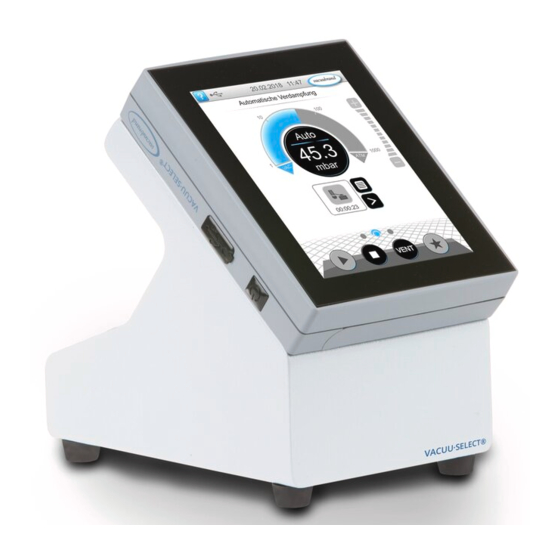
Product description 3.2 Product views Product views 3.2.1 3.2.1 VACUU·SELECT Complete (schematic design) VACUU·SELECT Complete (schematic design) The controller has a color display with touchscreen. Depending on the type of installation, the display can be rotated by 90°. All controller versions have the same connections, as described here in the example for the lab scaffold version. - Page 23 Product description Rear view Example Back and interfaces, lab scaffold version Meaning Power supply via VACUU·BUS VACUU·BUS plug‑in power supply RJ45 socket – LAN connection Stand holder with wing nut USB port, type A Rating plate Chemically resistant in‑line solenoid valve Connection sockets for VACUU·BUS VACUU·BUS components...
- Page 24 Product description Top view Example Plan view, lab scaffold version Stand holder with wing nut Meaning Chemically resistant in‑line solenoid valve Stand panel VACUU·SELECT VACUU·SELECT Sensor Sensor Valve block with connections Wall bracket (option) 20901171_EN_VACUU·SELECT-Komp_V1.4_291021...
-
Page 25: Vacuu·select Sensor
Product description 3.2.2 3.2.2 VACUU·SELECT Sensor VACUU·SELECT Sensor The vacuum sensor is mounted on the VACUU·SELECT VACUU·SELECT Description of VACUU·SELECT Complete. Communication with the controller takes place via the Complete Sensor VACUU·BUS VACUU·BUS. Two versions of the VACUU·SELECT VACUU·SELECT Sensor Sensor are available –... -
Page 26: Chemically Resistant In-Line Solenoid Valve
Product description 3.2.3 3.2.3 Chemically resistant in‑line solenoid valve Chemically resistant in‑line solenoid valve The fitted chemically resistant in‑line solenoid valve comprises an electromagnetic drive and valve block, and is used as a vacuum regulating valve. A built‑in non‑return valve prevents this from af‑ fecting nearby applications on one vacuum supply. -
Page 27: Vacuu·bus Peripheral Devices (Option)
Product description 3.3 VACUU·BUS peripheral devices (option) VACUU·BUS peripheral devices (option) External valves, level sensors and vacuum sensors (up to the VACUU·BUS principle fine vacuum range) are components that can be connected via VACUU·BUS directly to the controller. VACUU·BUS components can be easily added or removed at any time via component detection. -
Page 28: Example
Product description 3.4 Example Example Local area vacuum network Example Local area vacuum network with rotary evaporation Meaning Lab furniture Example: rotary evaporator VACUU·LAN – local area vacuum network with three valve modules Vacuum hose for application Vacuum hose from vacuum pump/local area vacuum network VACUU·SELECT Complete 20901171_EN_VACUU·SELECT-Komp_V1.4_291021... -
Page 29: Remote Control And Interfaces
Product description 3.5 Remote control and interfaces Remote control and interfaces As of Softwareversion V1.04/V1.00 of the VACUU·SELECT VACUU·SELECT , com‑ munication will be supported via RS‑232 as well as Modbus TCP. This enables you to remotely monitor and control the controller from a central location, for example with a PC or process control system. -
Page 30: Installation And Connection
Installation and connection Installation and connection Installation and connection 4.1 Transport Transport Products from VACUUBRAND are packed in sturdy, recyclable packaging. The original packaging is accurately matched to your product for safe transport. If possible, please keep the original packaging, e.g., for >... -
Page 31: Benchtop Version
Installation and connection NOTE NOTE Condensate can damage the electronics. A large temperature difference between the storage location and the installation location can cause condensation. After goods receipt or storage, allow your vacuum device to > acclimatize for at least 3‑4 hours before initial use. 4.2.1 4.2.1 Benchtop version Benchtop version... - Page 32 Installation and connection Mount the wall bracket Mount the wall bracket Preparation: 1. Use the drilling template to mark the dimensions on the > Have the tool and fittings surface where the wall brack‑ ready; e.g., impact drill , et should be mounted. masonry drill Ø6 mm, wall plugs size 6, universal screws, min.
- Page 33 Installation and connection Mounted wall bracket with Alternatively, the wall brack‑ controller. et can be mounted so that it is pivoted at an angle. Pivot stand holder To use the controller horizontally, the stand holder can be pivoted Pivot stand holder 90°...
-
Page 34: Built-In Version
Installation and connection 4.2.3 4.2.3 Built‑in version Built‑in version In the built‑in version, spring clips are fitted on the back of the Use as built‑in device controller. This means the controller can be clipped directly into the installation cut‑out of lab furniture or a control cabinet. The display can be pivoted so that the controller can be clipped into place either horizontally or vertically. - Page 35 Installation and connection Pivot valve block Depending on the installed orientation, the valve block can be pivoted 90°, e.g., for better access and connection of the hoses. Pivot valve block of the built‑in version 90° Preparation: 1. Turn the fastening screw half a turn to the left.
-
Page 36: Electrical Connection
Installation and connection 4.3 Electrical connection Electrical connection > Lay the connection cable such that it cannot be damaged by IMPORTANT! sharp edges, chemicals, or hot surfaces. Power supply via plug‑in power supply* Plug‑in power supply * Short-circuit-proofed multi-voltage power supply with integrated overload protection and changeable mains plugs: (a) valid until 11/2020 (b) valid from 12/2020... - Page 37 Installation and connection Connect plug‑in power supply to the controller > Insert the VACUU BUS cable of the plug‑in power supply into the plug‑in connection of the controller. Power supply via plug‑in power supply Connect power supply > Insert the plug‑in power supply into the power outlet. 20901171_EN_VACUU·SELECT-Komp_V1.4_291021...
-
Page 38: Vacuum Connection
Installation and connection 4.4 Vacuum connection Vacuum connection WARNING Risk of bursting due to overpressure Prevent uncontrolled overpressure, such as when > connecting to a locked or blocked tubing system. Vacuum connection is carried out at the back of the controller, at the chemically resistant in‑line solenoid valve. - Page 39 Installation and connection Connect PTFE hose Required connection material: PTFE hose. OUT Connect Vacuum connection vacuum pump or PTFE VACUU·LAN. IN Connect application 1. Unscrew the union nuts and slide them on to the hoses. 2. Insert the hoses into the screw‑in connector and secure them with the union nuts.
-
Page 40: Venting Connection (Option)
Installation and connection 4.5 Venting connection (option) Venting connection (option) DANGER DANGER Risk of explosion by venting with air. Depending on the application, venting can cause explo‑ sive mixtures to form or other hazardous situations to arise. Never vent processes with air which could form an >... -
Page 41: User Interface
User interface User interface User interface 5.1 Switch on controller Switch on controller Switch on device > Briefly press the ON/OFF button on the controller 5 The device starts up 5 Information is displayed Functions of the ON/OFF button ON/OFF Meaning ON/OFF button Switch on controller Switch on controller... -
Page 42: Touchscreen
User interface 5.1.1 5.1.1 Touchscreen Touchscreen The controller is a device operated via touchscreen. You can, for Touchscreen operation example, select, start, and stop an application by tapping the dis‑ play. By making various gestures, you can access advanced features: switch between views, edit applications, or use the help and con‑... -
Page 43: Screen Orientation
User interface In the delivered condition or following a reset to the factory set‑ tings, the data logger is switched off and recording of diagnostic data is preset to Minimal . The message about data storage appears after every controller restart. -
Page 44: Display And Operating Elements
User interface 5.4 Display and operating elements Display and operating elements The display and operating elements of the controller are summa‑ rized and explained in this chapter. > Refer to this chapter if you want to read about the meaning of a display or an operating element during operation. -
Page 45: Display Elements
User interface 5.4.2 5.4.2 Display elements Display elements Status bar Color Meaning Status bar color codes Standard Standard Gray Gray Warning Warning Yellow Error Error Sounds Sound Meaning Sounds Touch tone unless muted Touch tone unless muted ` Feedback entry Warning or error Warning or error ` Shows that an error or warning is present. - Page 46 User interface Pop‑up windows (context menus) Graphic Meaning Examples Numeric keypad with special buttons Numeric keypad with special buttons Pop‑up window ` Enter numerical values. ` Select a function using special buttons (AUS, ATM, AUTO). ` Min./max. values displayed. ` Values outside the permissible input range are not accepted.
-
Page 47: Operating Elements And Symbols
User interface 5.4.3 5.4.3 Operating elements and symbols Operating elements and symbols Status bar Symbol (icon) Meaning Access help Access help ` Tips for operation can be accessed from any menu level. USB connected USB connected ` Shows that a device is connected via USB. Ethernet connected Ethernet connected (option) - Page 48 User interface Operating elements – adjust pressure setpoint Symbol (icon) Meaning Pressure curve – analog pressure display Pressure curve – analog pressure display ` Adjust the pressure setpoint by moving the marker. Marker – pressure setpoint Digital pressure display Digital pressure display ` Adjust the pressure setpoint by tapping.
- Page 49 User interface Operating elements – process steps Button or icon Meaning Application icon Application icon Active Locked ` Tap briefly to open the parameter list. ` Press and hold to open the context menu. Shortcut Shortcut ` Open the applications menu. Right/left arrow Right/left arrow Process screen...
- Page 50 User interface Input field or selection field Input field or selection field Parameter list ` Tap to open a pop‑up window where you can enter values or select a function, even during operation. Input field for active process Blue Blue Input field for inactive process Black Black Operating elements for control Button Function Active...
-
Page 51: Operation
Operation Operation Operation The controller has an application‑based user interface. You can select, edit and start an application from a series of pre‑defined applications. Fine adjustments for the selected application can be made at any time in the parameter list or directly via the 5.4.3 5.4.3 Operating elements and symbols on page 47 Operating elements and symbols on page... -
Page 52: 6.1.2 Adjust Pressure Setpoint
Operation 6.1.2 6.1.2 Adjust pressure setpoint Adjust pressure setpoint The controller offers a variety of options for adjusting the pres‑ sure setpoint during operation. Change pressure setpoint in the parameter list Tap/press lightly > Enter a target value in the pop‑up and confirm the entry Fine adjustment via step buttons ‑... - Page 53 Operation Adjust pressure setpoint using marker Hold down and drag Release Adjust pressure setpoint in digital pressure display Tap/press lightly > Enter a target value in the pop‑up and confirm the entry. 20901171_EN_VACUU·SELECT-Komp_V1.4_291021...
-
Page 54: 6.1.3 Vent
Operation 6.1.3 6.1.3 Vent Vent Vent briefly Brief venting > Tap/press lightly Slight pressure increase. Vacuum control running. Vent to atmospheric pressure Continuous venting > Hold down Vacuum control stops. ~ 3 sec Pressure increase until atmospheric pressure is reached. -
Page 55: Stop Application
Operation 6.1.4 6.1.4 Stop application Stop application Stop application > Tap/press lightly Vacuum control stops. 6.2 Application parameters ( Application parameters (parameter list) parameter list) In the parameter list, you can individually change and adapt vari‑ ous process‑related values before and during operation. Adjust parameter ... - Page 56 Operation Example Adjust motor speed parameter 3. Enter the required motor 4. Confirm entry. speed in the pop‑up. Cancel Confirm Tap/press lightly 5. Confirm the change in the Once the application starts, parameter list. the motor runs at the adjusted speed.
-
Page 57: Pressure Graph
Operation 6.3 Pressure graph Pressure graph The pressure graph is on the same level as the process screen. The menu shows pressure curves of measured vacuum values. The pressure curve is shown until a new application is started, at which point it is replotted. View Pressure graph ... -
Page 58: Main Menu
Operation 6.4 Main menu Main menu The main menu is on the same level as the process screen. The submenus of the controller can be accessed from the main menu. View main menu > Example View main menu Swipe right >... -
Page 59: Applications
Operation 6.4.1 6.4.1 Applications Applications This menu lists all applications: standard applications, favorites, and newly created applications. View application menu View applications > submenu Tap/press lightly Display the applications submenu. Show context menu Example > View context menu ~ 3 sec for applications... -
Page 60: Favorites
Operation 6.4.2 6.4.2 Favorites Favorites Applications marked as favorites are identified by a star on the button. Add favorites Example Add favorites ~ 3 sec Hold down Tap/press lightly Confirm Text changed in the Button with favorites star. context menu. -
Page 61: Main Menu
Main menu Main menu Main menu 7.1 Advanced operation Advanced operation 7.1.1 7.1.1 Application editor Application editor In the application editor, you can compile your own application using the building‑block principle and save it with an appropriate name. Existing applications can be used in the application editor as tem‑ plates, and then saved with a new name. -
Page 62: Menu Bar And Description
Main menu Application editor display > Tool tips help Hold vacuum when selecting process steps. Menu bar Overview of process steps Building blocks with individual process steps which you can scroll through and select as required. 7.1.2 7.1.2 Menu bar and description Menu bar and description Menu bar Icon buttons... -
Page 63: Overview Of Process Steps
Main menu Description of the application New application: this name is automatically changed as soon as you give your application an appropriate name using Save as. Description of the new application: here, you can enter a brief Example: description of your application. This description appears later in Application editor the parameter list. -
Page 64: Process End
Main menu The process step sections are numbered from top to bottom, from 1 to n. If a process step section is added, shifted or removed, the numbering is adjusted automatically. 7.1.4 7.1.4 Process end Process end Process end means the defined end of an application. Process steps can only be placed in front of this. -
Page 65: Edit Application
Main menu 7.1.5 7.1.5 Edit application Edit application Create a new application Example Create a new application Tap/press lightly Hold down and drag Release Save as Confirm Exit menu 20901171_EN_VACUU·SELECT-Komp_V1.4_291021... - Page 66 Main menu Example Edit new application Tap/press lightly Hold down Save Confirm Exit menu New application listed with white symbol in applications submenu. 20901171_EN_VACUU·SELECT-Komp_V1.4_291021...
-
Page 67: Remove Process Step
Main menu 7.1.6 7.1.6 Remove process step Remove process step Change application Example Edit existing application Hold down Tap/press lightly Hold down and drag Release Save Exit menu The removed process step is no longer displayed in the parameter list of the application. 20901171_EN_VACUU·SELECT-Komp_V1.4_291021... -
Page 68: Settings
Main menu 7.1.7 7.1.7 Settings Settings In this submenu you can adjust the display, switch to another language, and make presettings for connected VACUU·BUS pe‑ ripheral devices. View settings submenu Example > Main menu \ Settings \ Basic settings Tap/press lightly... - Page 69 Main menu In the Basic Settings you can Example specify default settings for your Overview process: Context menu settings Overview of Description of basic settings possible basic settings Function Setting Description Autostart Off / On Off: The controller remains on Stop when the power supply is switched on.
-
Page 70: Settings/Administration
Main menu 7.1.8 7.1.8 Settings/administration Settings/administration Admin area of the controller – only for authorized staff. View administration submenu Example Main menu \ Settings \ Administration Tap/press lightly Submenu with buttons for administrative submenus. Meaning of the context menus Adjustments for date and time. - Page 71 Main menu Default settings for integrating the controller into your Network. Activate/deactivate remote control via Modbus. Default settings for Serial port and alignment of the communication settings (COM) for RS‑232. Activate/deactivate remote control via RS‑232. Activate command for loading software update from connected USB flash drive.
-
Page 72: Administration - Import/Export
Main menu 7.1.9 7.1.9 Administration – import/export Administration – import/export View import/export submenu > Example Main menu \ Settings \ Administration \ Import/Export Tap/press lightly Meaning of the context menus You can use the export function to ... -
Page 73: Administration - Vacuu·bus
Main menu 7.1.10 7.1.10 Administration – VACUU·BUS Administration – VACUU·BUS The VACUU·BUS submenu simplifies the detection and manage‑ ment of VACUU·BUS components. View VACUU·BUS submenu Example > Main menu \ Settings \ Administration \ VACUU·BUS Tap/press lightly The buttons retrieve context menus. - Page 74 Main menu With component configuration, the addresses of connected components can be easily changed or reassigned. Using component activation, connected VACUU·BUS components can be individually activated or deactivated, i.e., the components can remain connected but are switched on or off at the controller as required for the ongoing process.
- Page 75 Function activation If you have a valid license, please follow the user prompts that ap‑ pear once you have inserted the USB stick with the license file. Alternatively, you can enter the license code using the on‑screen keyboard. https://www.vacuubrand.com/20901537 20901171_EN_VACUU·SELECT-Komp_V1.4_291021...
-
Page 76: Data Logger
Main menu 7.2 Data logger Data logger If the function is switched on, the data logger records time/pres‑ sure curves and saves these at specified intervals, for a duration of up to 30 days. A separate data file is saved for each process, from start to stop. -
Page 77: Service
Main menu 7.3 Service Service In this menu, you can find or download information about the de‑ vice. In the event of an error, please forward this information to our Service Department. 7.3.1 7.3.1 Service information Service information Calling up the Service submenu ... -
Page 78: Diagnostic Data
Main menu 7.3.2 7.3.2 Diagnostic data Diagnostic data To improve the diagnostics of the device condition in the event of an error or service, diagnostic data is stored on the device. The data can be downloaded onto a USB flash drive via the service menu and sent to our Customer service for evaluation. -
Page 79: Troubleshooting
Troubleshooting Troubleshooting Troubleshooting To identify errors and potential remedies, please refer to the Technical support troubleshooting table Error – Cause – Remedy Error – Cause – Remedy. For technical assistance or errors for which you require ad‑ ditional support, please contact your local distributor or our Service Department 8.1 Error messages Error messages... -
Page 80: Acknowledge Error Indication
Troubleshooting 8.1.2 8.1.2 Acknowledge error indication Acknowledge error indication Errors must be acknowledged after the fault has been remedied. Error information and acknowledgement View message Acknowledge Tap/press lightly Error message reset. 8.2 Error – Cause – Remedy Error – Cause – Remedy 8.2.1 8.2.1 Pop‑up message Pop‑up message... -
Page 81: General Faults
Troubleshooting Error Error ` Possible cause Remedy Personnel Specialist Error at analog No power supply. Connect power sup‑ I/O module ply. Specialist Error at Ambient temperature Eliminate cause of Peltronic too high, Peltronic over‑ overheating of the heated. Peltronic. - Page 82 Troubleshooting Error Error ` Possible cause Remedy Personnel Operator No display Power plug or plug‑in Check power connec‑ power supply not cor‑ tion or plug‑in power rectly plugged in or supply and cables. pulled out. Check VACUU·BUS Pumping unit switched plug‑in connection off.
-
Page 83: Device Fuse
Troubleshooting 8.3 Device fuse Device fuse There is a device fuse, type: Nano fuse 4 A/t, on the circuit board of the controller. If tripped, the fuse can be replaced under ESD conditions after the cause has been remedied. NOTE NOTE Damage possible if work is performed incorrectly. - Page 84 Troubleshooting Change device fuse 2. Carefully lift the display. 3. Carefully pivot back the display. 4. Lever the fuse out of the base. 5. Insert the new fuse in the base. 6. Close the housing tightly. 7. Tighten the housing screws using the Torx screwdriver (torque 1.1 Nm) and secure the attachments when work is...
-
Page 85: Appendix
Appendix Appendix Appendix 9.1 Technical information Technical information Type Vacuum controller VACUU·SELECT Complete Software version V1.06 / V1.00 9.1.1 9.1.1 Technical data Technical data Ambient conditions (US) Technical data Working temperature 10‑40 °C 50–104 °F Storage/transport ‑10‑60 °C 14‑140 °F temperature Max. - Page 86 Appendix Chemically resistant in‑line solenoid valve Technical data (US) Power supply 24 V DC ±10 % Valve connector 3‑pole on VACUU·BUS Power consumption, approx. 0.22 A Power Switching frequency/minute, max. Switching state NO contact NC contact Leak rate 1*10 mbar l/s ‑2 Operating pressure 1.5 bar...
- Page 87 Appendix Benchtop version – dimensions (mm) Dimensions Lab scaffold version – dimensions (mm) Built‑in version – dimensions (mm) 20901171_EN_VACUU·SELECT-Komp_V1.4_291021...
-
Page 88: Rating Plate
Appendix 9.1.2 9.1.2 Rating plate Rating plate In the event of an error, make a note of the type and serial > number on the rating plate. When contacting our Service Department, please provide > the type and serial number from the rating plate. This will allow us to provide you with specific support and advice for your device. -
Page 89: Wetted Materials
Appendix 9.1.3 9.1.3 Wetted materials Wetted materials Component Wetted materials Wetted materials Sensor Aluminum oxide ceramic, gold‑ coated (if applicable) Measurement chamber Venting valve seal FFKM Option: blind plugs without venting Epoxy resin valve Seals Chemically resistant fluoroelastomer, PTFE Connections to pump/application PVDF Valve block O‑rings... -
Page 90: Ordering Information
Appendix 9.2 Ordering information Ordering information Vacuum controller Ordering information Order no. VACUU·SELECT benchtop version 20700070 VACUU·SELECT lab scaffold version 20700080 VACUU·SELECT built‑in version 20700060 Accessories Order no. Vacuum hose DN 6 mm (l = 1000 mm) 20686000 PTFE hose KF 16 20686031 Silicone rubber hose 3/6 (vent with inert gas) 20636156... -
Page 91: Licensing Information And Data Protection
20901170 Sources of supply Purchase original accessories and original spare parts from a International sales offices and subsidiary of VACUUBRAND GMBH + CO KG or your local dis‑ distribution tributor. Information about our complete product range is available > in the current product catalog. -
Page 92: Service
Appendix 9.4 Service Service Take advantage of the comprehensive range of services avail‑ Service offer and able from VACUUBRAND GMBH + CO KG. service range Services in detail Product consultation and practical solutions ƒ Fast delivery of spare parts and accessories ƒ... -
Page 93: Index
Appendix 9.5 Index Index Goods receipt ....... 30 Abbreviations ........ 11 Rating plate ......25, 88 Action steps ........10 Remove favorites ......60 Handling instructions ....10 Add favorites ........ 60 Responsibility matrix ....15 Health and Safety Clearance form 92 Additional symbols ...... -
Page 94: Ec Declaration Of Conformity
Hersteller / Manufacturer / Fabricant: Hersteller / Manufacturer / Fabricant: VACUUBRAND GMBH + CO KG · Alfred-Zippe-Str. 4 · 97877 Wertheim · Germany VACUUBRAND GMBH + CO KG · Alfred‑Zippe‑Str. 4 · 97877 Wertheim · Germany VACUUBRAND GMBH + CO KG · Alfred-Zippe-Str. 4 · 97877 Wertheim · Germany Hiermit erklärt der Hersteller, dass das Gerät konform ist mit den Bestimmungen... - Page 95 Appendix 20901171_EN_VACUU·SELECT-Komp_V1.4_291021...
- Page 96 Technology for Vacuum Systems VACUUBRAND > Support > Manuals Manufacturer: VACUUBRAND GMBH + CO KG Alfred‑Zippe‑Str. 4 97877 Wertheim GERMANY Phone: ƒ Head office +49 9342 808‑0 ƒ Sales +49 9342 808‑5550 ƒ Service +49 9342 808‑5660 Fax: +49 9342 808‑5555 Email: info@vacuubrand.com...
Need help?
Do you have a question about the VACUU-SELECT and is the answer not in the manual?
Questions and answers