vacuubrand CVC 3000 detect Instructions For Use Manual
Vacuum controller
Hide thumbs
Also See for CVC 3000 detect:
- Instructions for use manual (124 pages) ,
- Instructions for assembly (12 pages) ,
- Instructions for use manual (43 pages)

Related Manuals for vacuubrand CVC 3000 detect


Summary of Contents for vacuubrand CVC 3000 detect
- Page 1 Vacuum controller CVC 3000 detect Instructions for use Original instructions EN OI no.: 20901317...
- Page 2 ® (US-Reg.No 3,833,788), VACUUBRAND (US-Reg.No 3,733,388), ® VACUU·VIEW , GREEN VAC (US-Reg.No. 4,924,553), VACUU·PURE ® ® ® (US-Reg No. 5,559,614) and also the shown company logos are registered trademarks of VACUUBRAND GMBH + CO KG in Germany and/or other countries.
- Page 3 page 3 of 80 Achtung: Die vorliegende Betriebsanleitung ist nicht in allen EU-Sprachen verfügbar. Der Anwender darf die beschriebenen Geräte nur dann in Betrieb nehmen, wenn er die vorliegende Anleitung versteht oder eine fachlich korrekte Übersetzung der voll- ständigen Anleitung vorliegen hat. Die Betriebsanleitung muss vor Inbetriebnahme der Geräte vollständig gelesen und verstanden werden, und alle geforderten Maß- nahmen müssen eingehalten werden.
- Page 4 page 4 of 80 Bemærk: Denne manual foreligger ikke på alle EU sprog. Brugeren må ikke be- tjene apparatet hvis manualen ikke er forstået. I det tilfælde skal en teknisk korrekt oversættelse af hele manual stilles til rådighed. Manual skal være gennemlæst og forstået før apparatet betjenes og alle nødvendige forholdsregler skal tages.
- Page 5 page 5 of 80 Figyelem! Ez a kezelési utasítás nem áll rendelkezésre az EU összes nyelvén. Ha a felhasználó nem érti jelen használati utasítás szövegét, nem üzemeltetheti a készüléket. Ez esetben a teljes gépkönyv fordításáról gondoskodni kell. Üzembe helyezés előtt a kezelőnek végig kell olvasnia, meg kell értenie azt, továbbá az üzemeltetéshez szükséges összes mérést el kell végeznie.
- Page 6 page 6 of 80 Attentie: Deze gebruiksaanwijzing is niet in alle talen van de EU verkrijgbaar. De gebruiker moet niet met dit apparaat gaan werken als voor hem/haar de gebruiks- aanwijzing niet voldoende duidelijk is. Bij gebruik van deze apparatuur is het nood- zakelijk een technisch correcte vertaling van de complete gebruiksaanwijzing te hebben.
- Page 7 page 7 of 80 Varning: Denna instruktion är inte tillgänglig på alla språk inom EU. Användaren får inte starta utrustningen om hon/han inte förstår denna instruktion. Om så är fallet måste en tekniskt korrekt instruktion göras tillgänglig. Instruktionen måste läsas och förstås helt före utrustningen tas i drift och nödvändiga åtgärder göres.
-
Page 8: Reset / Language Selection
page 8 of 80 Reset / Language selection press both switch off C V C 30 00 V 2. 0 D eut sch P or t uguê E ngl i sh Ρ y ccк ий Fr ança i s P ol ski I t al i ano N ed erl . -
Page 9: Table Of Contents
page 9 of 80 Contents Reset / Language selection ..........8 Safety information! ............11 Important information! ................11 General information ................13 Intended use..................13 Setting up and installing the equipment ..........14 Ambient conditions ................15 Operating conditions ................. 16 Safety during operation .............. - Page 10 page 10 of 80 Readjustment ..............53 Calibration in the factory ..........55 Cleaning the pressure transducer ........55 Interface parameters ............57 Setting of the interface ..............57 Read commands ”CVC 2000” ............58 Write commands ”CVC 2000” ............59 Read commands ”CVC 3000”...
-
Page 11: Safety Information
Make operating personnel aware of dangers arising from the pump and the pumped substances. VACUUBRAND disclaims any liability for inappropri- ate use of this controller and for damage from failure to follow instructions contained in this manual. - Page 12 page 12 of 80 ➨ DANGER indicates a hazardous situation which, if not avoided, will result in death or serious injury. + WARNING indicates a hazardous situation which, if not avoided, could result in death or serious injury. • CAUTION indicates a hazardous situation which, if not avoided, could result in minor or moderate injury.
-
Page 13: General Information
page 13 of 80 General information Remove all packing material from the packing box. Re- move the product from its packing-box and retain all pack- aging until the equipment is inspected and tested. Inspect the equipment promptly and carefully. If the equipment is damaged, notify the supplier and the carrier in writing within three days. -
Page 14: Setting Up And Installing The Equipment
• Check the power source and the equipment’s rating plate to be sure that the power source and the equipment match in voltage, phase, and frequency. If the power supply is not provided by a VACUUBRAND plug-in power supply unit or not by another VACUUBRAND... -
Page 15: Ambient Conditions
page 15 of 80 peripheral device (e.g. chemistry pumping unit PC 3001 VARIO select), the power supply must provide a stabilized 24 V DC voltage which must not supply more than 6.25 A even in the event of a fault. If additional overcurrent pro- tection devices (e.g. -
Page 16: Operating Conditions
page 16 of 80 • This product may only be used indoors in a non-explo- sive atmosphere, and in a dry environment. Adopt suitable measures in case of differences from recommended conditions, e.g., installation in higher altitudes (risk of insufficient cooling), conductive pollu- tion or external condensation on the product. -
Page 17: Safety During Operation
page 17 of 80 • Ensure that the materials of the controller’s wetted parts are compatible with the substances in the vacu- um system, see section “Technical data”, pg. 21. Safety during operation ➨ Adopt suitable measures to prevent the release of dangerous, toxic, explosive, corrosive, noxious or pol- luting fluids, vapors and gases. -
Page 18: Maintenance And Repair
page 18 of 80 nected devices. Provide appropriate protective measures to allow for the possibility of failure and malfunction. The pro- tective measures must also allow for the requirements of the respective application. Maintenance and repair ➨ Switch off the controller. Disconnect the power sup- ply and wait five seconds before starting maintenance to allow the capacitors to discharge. -
Page 19: Important Information: Equipment Marking (Atex)
Important information: Equipment marking (ATEX) Only valid for products with ATEX marking. If the ATEX marking is shown on the rating plate of the respective product, VACUUBRAND GMBH + CO KG assures, that the device complies with the provi- sions of the directive 2014/34/EU. The applied harmonized stand- ards are indicated in the EC Declaration of Conformity of the Ma- chinery (see instructions for use). - Page 20 page 20 of 80 • The equipment is designated for a low degree of mechanical stress and has to be installed in a way so that it cannot be damaged from outside. Pumping units have to be installed so that they are protected against shocks from the outside and against glass splinters in the event of breakage (implosion).
-
Page 21: Technical Data
21 of 80 Technical data Technical data of controller Controller CVC 3000 detect ATEX approval if the ATEX marking II 3/- G Ex h IIC T3 Gc X Internal Atm. is shown on the rating plate only Inner part (pumped gases) Tech.File: VAC-EX02... - Page 22 ** if pumping potentially explosive atmospheres: 50 °F to 104 °F (+10°C to +40°C) ➨ The VACUUBRAND CVC 3000 detect controller can only be operat- ed with components compatible to the VACUUBRAND VACUU•BUS system, see accessories.
-
Page 23: Technical Data Of Power Supply
page 23 of 80 Technical data of power supply Power supply (wall plug)* 20612090 (30 W) 20612089 (25 W) Input voltage (±10%) 100-240 V~ / 47-63 Hz 100-240 V~ / 47-63 Hz Maximum current draw 0.8 A 0.7 A Overvoltage category Ambient temperature range 32°F to 104°F -4°F to 140°F... -
Page 24: Wetted Parts
page 24 of 80 Wetted parts Components Wetted materials Sensor Aluminum oxide ceramic Connection to vacuum pump / application PVDF Sensor housing PPS / glass fiber Sensor seal Chemically resistant fluoroelastomer Venting valve seal FFKM Valve block O-ring In-line valve housing PVDF Non-return valve seal FFKM... -
Page 25: Use And Operation
“Accessories”, pg. 65) and optional coolant and venting valves. When switching on the controller CVC 3000 detect for the very first time, a menu to select the language of the controller menu is displayed. Select the desired language (e.g., ”English”) by turning the selection knob and press to confirm. - Page 26 page 26 of 80 Connected components (e.g., in-line valve, level sensor, external pres- sure transducer 3000 series) are automatically identified. Identical com- ponents must be configured beforehand; information upon request. Do not use more than one controller within the same VACUU•BUS system.
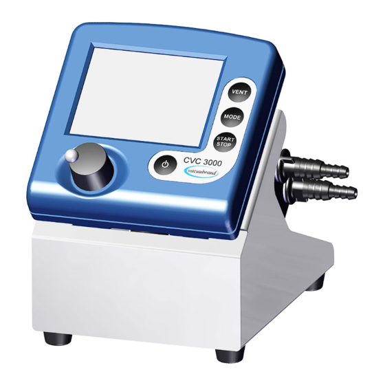
- Page 27 27 of 80 CVC 3000 detect (table top unit) solenoid operated in-line valve VV-B 6C vacuum connection to application connection to pump CVC 3000 detect (rear side) jacks for connection of connection plug of the power supply VACUU•BUS components (e.g., coolant valve)
- Page 28 page 28 of 80 Wall mount for tripod bracket (dimensions in mm) Attention: Do not assemble or remove plug connections off-axis! Orient the plug correctly before inserting. To connect additional components use VACUU•BUS Y-adapters and extension cables. Depending on technical version the con- nections of the VACUU•BUS cables are equipped with a nib.
-
Page 29: Notes On Connecting And Operating The Controller
The controller can switch a possibly connected coolant and/or venting valve. The CVC 3000 detect is equipped with an internal capacitive pressure transducer with ceramic diaphragm. It measures the actual pressure in- dependently of the gas type, and with reference to the vacuum, i.e., ab- solute. -
Page 30: Display And Symbols
page 30 of 80 Display and symbols Vac control 1013 . 2 mbar Selected function (displayed in the upper left corner): A ”function” is one of the following operation modes of the CVC 3000 de- tect controller: Pump down / Vac control / detect / Program / VACUULAN / Configu- ration Other display symbols: 1013.2 Actual absolute pressure at the pressure transducer mbar / Torr / hPa... - Page 31 page 31 of 80 Vacuum control to a preset vacuum value (here: 100 mbar/Torr/hPa) / Actual pressure is in the range ”Set vacuum + hysteresis” Determination of boiling vacuum in program function / det. Determination of boiling vacuum in detect function Flashing: The actual pressure is greater than the preset max- imum value (“Maximum“) Minimum value (“Minimum“) reached...
-
Page 32: Notes On Selecting The Function
32 of 80 Notes on selecting the function The CVC 3000 detect controller can be adapted to the specific applica- tion by choosing the appropriate function depending on the connected components and the requirements of the application. Automatic detection of the components When switching on the controller, the configuration of the connected com- ponents is checked automatically. - Page 33 page 33 of 80 • Coolant valve ”detect” • Provides fully automatic boiling point determination and switches an in-line valve and/or a pump to maintain that pressure in two-point con- trol. • Coolant valve ’’Program’’ • Control in-line valve or pump based on time and pressure preselec- tions.
-
Page 34: Menu Guide
page 34 of 80 Menu guide Pump down Minimum Delay Duration - - - - - - Graphic - - - - - - Pump down - - - - - - - Back - - - - - - - 1013 . - Page 35 page 35 of 80 Vac control Set vacuum 75 Torr Hysteresis Auto Maximum Delay Duration - - - - - - Graphic - - - - - - Vac control - - - - - - - Back - - - - - - - 1013 .
-
Page 36: Pump Down Function
page 36 of 80 Pump down function ➨ Continuous pumping with pressure and time settings • Operation of a vacuum pump via in-line valve • Operation of a vacuum pump without in-line valve with VMS (Vac- uum Management System, see “Accessories”, pg. 65) Preselections + Use the selection knob to select the parameters. -
Page 37: Vac Control Function
page 37 of 80 The screen-shot shows the factory-set values. Pump down Pump down 10 mbar 00:00:00 00:03:50 Minimum Delay Duration - - - - - - Graphic - - - - - - - - - - - - - Back - - - - - - - When selecting ”Graphic”... - Page 38 page 38 of 80 + Set vacuum: The ”Set vacuum” is the lower set point for two-point vacuum control. The ”Set vacuum” is adjustable in a range of 0-795 Torr (0-1060 mbar). + Hysteresis: The ”Hysteresis” is the control bandwidth of the two-point control.
- Page 39 page 39 of 80 The screen-shots show the factory-set values. Vac control Vac control 00:00:00 Set vacuum 75 Torr Hysteresis Auto Maximum Delay Duration - - - - - - Graphic - - - - - - - - - - - - - Back - - - - - - - When selecting ”Graphic”...
-
Page 40: Detect Function
page 40 of 80 detect function ➨ Controls a vacuum pump by switching an in-line valve. Automatic determination of the boiling vacuum and automatic switching to the ”Vac Control” function once the boiling vacuum has been determined. The determined boiling vacuum is used in the ”Vac Control” func- tion as ”Set vacuum”. - Page 41 ➨ Attention: The ”detect” function is designed for operation with a stand-alone vac- uum pump. If the CVC 3000 detect is to be operated in a vacuum network you must ensure that during the determination of the boiling vacuum no disturbance due to other users will occur.
-
Page 42: Program Function
page 42 of 80 Program function ➨ P ermits ten programs to be defined and stored, each with up to ten program steps with preset values for vacuum and time. + Edit: Use to define the preset values for the process run: Time: Defines either the process runtime for each program step to reach a preset vacuum level or, if programming a ”Step”, the runtime after having achieved the vacuum level. - Page 43 page 43 of 80 + Delay: ”Delay” determines the time the coolant valve remains open af- ter the process has been stopped. Determines also the time the pump (only with VMS module and in-line valve) remains running after the process has been stopped. The ”Delay”...
-
Page 44: Application Example
page 44 of 80 This program can be transferred to a storage space and edited. Once the program is finished, the clock symbol starts to flash. Confirm the end of the program by pressing START/STOP (clock symbol will dis- appear). Attention: If ”Autostart”... - Page 45 page 45 of 80 sure unit) and 20 Torr/mbar/hPa. The determined boiling vacuum is used in the ”Vac Control” function as ”Set vacuum”. In case no boiling vacuum is detected, the controller controls to 20 Torr/mbar/hPa. The following step starts once the cumulative process time reaches the set limit (1 hour/60 minutes), even if the preset pressure (20 Torr/mbar/hPa) has not been reached.
-
Page 46: Vacuulan Function
46 of 80 VACUULAN function ➨ Optimizes vacuum control for vacuum networks (e.g., VACUUBRAND VACUU•LAN) - pump control only with VMS Preselections + Use the selection knob to select the parameters. + Set vacuum (the lower switch-off value): If the pressure drops below the ”Set vacuum”, a time-meter starts to run. - Page 47 page 47 of 80 This screen-shot shows the factory-set values. VACUULAN VACUULAN 40 mbar 00:00:00 00:13:00 Set vacuum 19 Torr Switch on 150 Torr Delay 15 min - - - - - - Graphic - - - - - - - - - - - - - Back - - - - - - - When selecting ”Graphic”...
-
Page 48: Application Examples
page 48 of 80 Application examples Assembly of a vacuum system + Assemble vacuum connection lines between controller, vacuum pump (diaphragm pump with in-line valve or Vacuum-Management-System) and vacuum application. + Assemble electrical connections. + Connect coolant if necessary. Vacuum for distillation and evaporation (e.g., rotary evaporator) 1. -
Page 49: Vacuum For Gel Dryer, Drying Chambers And Vacuum Concentrators
page 49 of 80 has evaporated and the controller is set again to the ”detect” function, further components of the solvent mixture can be evaporated by re- starting the ”detect” function. 2. Semi-automatic distillation and evaporation + Select ”Pump down” function. + Start process by pressing ”START/STOP”... -
Page 50: Vacuum For Filtration And Suction
page 50 of 80 alternatively: + Select ”Vac control” function to dry at a predetermined vacuum level. + Set ”Set vacuum” to the preferred evaporation vacuum of the solvent. Adapt ”Hysteresis” if necessary. + Set a process time (”Duration”) if necessary. + Start process by pressing ”START/STOP”... -
Page 51: Configuration
page 51 of 80 Configuration In the ”Configuration” menu the device parameters are preselected. After 20 seconds without action the function ”Configuration” and its sub- menus (except submenu ”Sensors”) are quit automatically without stor- ing any possibly changed parameter. Preselections + Use the selection knob to select the parameters. - Page 52 page 52 of 80 + Autostart: If ”Autostart” is set to ”On” the controller restarts a running process automatically after a mains failure. If this is unwanted, set ”Autostart” to ”Off”. Attention: If ”Autostart” is preselected, the process starts immediately after power failure without pressing any fur- ther key.
-
Page 53: Readjustment
page 53 of 80 Readjustment The vacuum gauge was adjusted using factory standards, which are traceable through regular calibration in an ac- credited laboratory (DAkkS calibration laboratory) to the German national pressure standard. Depending on the process and/or accuracy requirements, check the adjust- ment and readjust if necessary. - Page 54 page 54 of 80 Adjustment under vacuum An adjustment under vacuum is only possible if the pressure is lower than 15 Torr (20 mbar) 0 Torr absolute. ➨ Evacuate the measurement connection of the controller or in case that of a connected optional external gauge head VSK 3000 to a pres- sure <...
-
Page 55: Calibration In The Factory
Federal Republic of Germany for the field of metrology and certain sectors of safety engineering). DAkkS calibration of the CVC 3000 detect pressure transducer ....20900215 Cleaning the pressure transducer Attention: Never use a pointed or sharp-edged tool to clean the pressure transducer. - Page 56 ➨ Rinse the measurement chamber several times with alcohol in order to remove all solvent residues. ➨ Allow the pressure transducer to dry. ➨ Readjust the pressure transducer if necessary. Readjustment of the controller CVC 3000 detect See section “Readjustment”, pg. 53.
-
Page 57: Interface Parameters
The factory-set read and write commands are completely compatible with the VACUUBRAND CVC 2000 controller (see sections ”Read / Write commands CVC 2000”). An extended instruction set is available using the command ”CVC 3”... -
Page 58: Read Commands "Cvc 2000
page 58 of 80 ➨ A maximum of ten commands per second is possible. ➨ Read commands and commands ”REMOTE”, ”CVC”, and ”STORE” can always be sent. The sending of other write commands is only pos- sible, if ”Remote on” is selected. ➨... -
Page 59: Write Commands "Cvc 2000
page 59 of 80 Command Operation Response Description 1XXX fault at pump electronics X1XX overpressure IN_ERR error code XX1X maloperation mode pressure transducer XXX1 last command to interface incorrect coolant valve closed 0XXX coolant valve open 1XXX venting valve closed X0XX venting valve open X1XX... - Page 60 page 60 of 80 Command Operation Parameter Description unit (mbar/Torr/hPa) according to pre- vacuum for switch OUT_SP_3 XXXX selection; see respective function for on (VACUU•LAN) parameter range OUT_SP_4 delay XX:XX hh:mm (hours:minutes) vacuum for auto- unit (mbar/Torr/hPa) according to pre- OUT_SP_5 matic switching XXXX...
-
Page 61: Read Commands "Cvc 3000
page 61 of 80 Read commands ”CVC 3000” Command Operation Response Description IN_PV_1 current pressure XXXX.X mbar/Torr/hPa unit according to preselections IN_PV_2 current speed XXX% 1-100% or ”HI” IN_PV_3 time XX:XX h:m process runtime (hours:minutes) pressure of all connected sensors, IN_PV_X pressure XXXX.X XXXX.X ... - Page 62 page 62 of 80 Command Operation Response Description 0XXXXX pump off 1XXXXX pump on X0XXXX in-line valve closed X1XXXX in-line valve open XX0XXX coolant valve closed XX1XXX coolant valve open XXX0XX venting valve closed XXX1XX venting valve open XXXX0X VACUU•LAN XXXX1X Pump down status process...
-
Page 63: Write Commands "Cvc 3000
page 63 of 80 Command Operation Response Description ”Maximum” for ”Vac control”, switch off IN_SP_5 XXXX mbar/Torr/hPa ”Minimum” for ”Pump down”) pressure unit according to preselections IN_SP_6 runtime XX:XX h:m process runtime (hours:minutes) time in program step y (0..9) IN_SP_P1y time XX:XX:XX h:m:s (hours:minutes:seconds) - Page 64 page 64 of 80 Command Operation Parameter Description set vacuum with unit according to preselection; see re- OUT_SP_V XXXX venting spective function for parameter range OUT_SP_2 speed speed in % or ”HI” unit according to preselection; see re- OUT_SP_3 start-up pressure XXXX spective function for parameter range OUT_SP_4...
-
Page 65: Accessories
page 65 of 80 * If remote operation is selected or deselected, the user has to ensure that no dangerous status of the system can occur due to the change of the mode of operation, and must also take appropriate safety precau- tions, especially if selecting remote operation interferes with a locally operated active process. - Page 66 66 of 80 Conversion of VACUUBRAND valves with DIN plug to VACUUBRAND valves with VACUU•BUS plug: VACUUBRAND-valve with DIN Conversion kit valve cable with plug VACUU•BUS plug In-line valve VV 6, 24V= (20674090) In-line valve VV 6C, 24V= (20674091)
-
Page 67: Troubleshooting
Remedy ❑ No display. ➨ Power supply not ✔ Plug in power supply. plugged in (wall plug)? ➨ CVC 3000 detect con- ✔ Switch on controller. troller switched off? ➨ VACUU • BUS cable ✔ Plug in VACUU • BUS of power supply not cable at controller. - Page 68 page 68 of 80 Fault Possible cause Remedy ❑ Warning triangle ➨ External venting valve ✔ Connect valve or replace and black valve removed or defective? with a new one or recon- symbol are flash- figure without valve. ing, two blips*. ❑...
- Page 69 VMS, NT VARIO / device. VARIO-B pump)? ❑ Controller does ➨ Controller in remote ✔ Control CVC 3000 detect not respond when mode? via interface or switch off pressing keys (ex- remote mode. cept ON/OFF). PC symbol is dis- played.
-
Page 70: Repair - Maintenance - Return - Calibration
3 or 4. These devices cannot be checked, maintained or re- paired. Also decontaminated devices must not returned to VACUUBRAND due to a residual risk. The same conditions apply to on-site work. No repair, maintenance, return or calibration is possi- ble unless the correctly completed health and safety clearance form is returned. - Page 71 page 71 of 80 If you do not wish a repair on the basis of our quotation, the device may be returned to you disassembled and at your expense. In many cases, the components must be cleaned in the factory prior to repair. For cleaning we use an environmentally friendly water based process.
-
Page 72: Warranty
72 of 80 Warranty VACUUBRAND shall be liable for insuring that this prod- uct, including any agreed installation, has been free of de- fects at the time of the transfer of risk. VACUUBRAND shall not be liable for the consequences... -
Page 73: Ec Declaration Of Conformity
page 73 of 80 EC Declaration of conformity... -
Page 74: Ukca Declaration Of Conformity
page 74 of 80 UKCA Declaration of conformity... - Page 75 page 75 of 80 This certificate is only valid for pumps with the respective mark (Li- censed Test mark) on the pump rating plate.
-
Page 76: China Rohs
page 76 of 80 China RoHS – a “Product Conformity Assessment” (PCA) procedure was performed. As defined in GB/T 26572 the “Maximum Con- centration Value” limits (MCV) apply t • • • • • • ous environmental pollution, cause serious bodily injury or damage to the user’s assets. 有毒有害物质或元素... - Page 77 page 77 of 80 表示该有毒有害物质在该部件所有均质材料中的含量均在GB/T 26572规定的限量要求以下。 表示该有毒有害物质至少在该部件某一均质材料中的含量超出GB/T 26572规定的限量要求。 电池、玻璃器皿和配件可能不属于所附设备所包含的内容,它们可能有各自单独的EFUP标记和/或可能正在维 护其部件EFUP标记的更新。 除上表所示信息外,还需声明的是,这些部件并非是有意用铅( )、 汞 ( )、铬( )、六价铬 ( )、多溴联苯( )或多溴二苯醚( )来制造的。 –...
- Page 78 page 78 of 80...
- Page 79 page 79 of 80...
- Page 80 VACUUBRAND > Support > Manuals Manufacturer: VACUUBRAND GMBH + CO KG VACUUBRAND GMBH + CO KG Alfred-Zippe-Str. 4 Alfred-Zippe-Str. 4 97877 Wertheim 97877 Wertheim GERMANY GERMANY Phone: Head office +49 9342 808-0 Sales +49 9342 808-5550 Service +49 9342 808-5660...
Need help?
Do you have a question about the CVC 3000 detect and is the answer not in the manual?
Questions and answers