vacuubrand VACUU-SELECT Instructions For Use Manual
Vacuum controller
Hide thumbs
Also See for VACUU-SELECT:
- User manual (108 pages) ,
- Instructions for use manual (96 pages) ,
- Instructions for use manual (40 pages)

Related Manuals for vacuubrand VACUU-SELECT


Summary of Contents for vacuubrand VACUU-SELECT
- Page 1 Technology for Vacuum Systems acuum ontroller VACUU·SELECT ® Instructions for use Original instructions EN OI no.: 20901059...
- Page 2 +49 9342 808‑5550 ƒ Service +49 9342 808‑5660 Fax: +49 9342 808‑5555 Email: info@vacuubrand.com Web: www.vacuubrand.com Thank you for purchasing this product from VACUUBRAND GMBH + CO KG. You have chosen a modern and techni- cally high quality product. 20901059_EN_VACUU·SELECT_V1.3_280119...
-
Page 3: Table Of Contents
Contents TABLE OF CONTENTS Introduction User information ....... . . 7 1.2 Manual structure. - Page 4 Contents User interface 5.1 Switch on controller ......38 5.1.1 Touchscreen ....... 39 5.1.2 Gestures for operation .
- Page 5 Contents 8.2 Error – Cause – Remedy ......75 8.2.1 Pop‑up message ......75 8.2.2 General faults .
- Page 6 Contents 20901059_EN_VACUU·SELECT_V1.3_280119...
-
Page 7: Introduction
ƒ the course of continuous product improvement. Copyright The content of this manual is protected by copyright. Only copies Copyright © and copyright law for internal use are allowed, e.g., for professional training. © VACUUBRAND GMBH + CO KG 20901059_EN_VACUU·SELECT_V1.3_280119... -
Page 8: Manual Structure
If your manual is incomplete, you can request a replace‑ Contact us ƒ ment. Alternatively, you can use our download portal: www.vacuubrand.com When contacting our Service Department, please have the ƒ serial number and product type at hand see Rating plate the product. -
Page 9: About This Document
Introduction 1.3 About this document 1.3.1 Display conventions Warning levels DANGER Display conventions Indicates an imminent hazardous situation. Disregarding the situation could result in extremely serious injury or death. Take appropriate action to avoid dangerous situations! > > WARNING Warns of a potentially hazardous situation. Disregarding the situation could result in serious injury or death. -
Page 10: Symbols And Icons
Introduction 1.3.2 Symbols and icons This manual uses symbols and icons. Safety symbols indicate specific risks associated with handling the product. Symbols and icons are designed to help you identify risks more easily. Safety symbols Explanation of safe‑ General warning symbol. Danger: electricity. -
Page 11: Handling Instructions (Action Steps)
Introduction Additional detailed descriptions of symbols (icons) and > > signals on the display can be found in chapter 5.4 Display and operating elements. 1.3.3 Handling instructions (action steps) Instructions (single step) Action steps as text > Perform the step described. 5 Result of action Instructions (multiple steps) 1. -
Page 12: Abbreviations
Introduction 1.3.4 Abbreviations abs. Absolute Abbreviations Separator flask Atmospheric pressure (bar graph, program) Interior diameter (di) Nominal diameter Outlet Fluoroelastomer Frequency converter Gas ballast ‑‑‑ ‑‑‑ Size hh:mm:ss Time in hours/minutes/seconds Pressure unit, hectopascal (1 hPa = 1 mbar = 0.75 Torr) Inlet Small flange... -
Page 13: Term Definitions
VACUU·SELECT Sensor. ® PC 510 select ** Pumping unit with valve‑actuated vacuum control. VACUU·BUS Bus system from VACUUBRAND for com‑ ® munication between peripheral devices with VACUU·BUS ‑enabled gauges and control‑ ® lers. The maximum permissible cable length is 30 m. -
Page 14: Safety Information
Incorrect use or any application which does not correspond to Improper use the technical data may result in injury or damage to property. 1 For vacuum pumps, sensors and accessories from VACUUBRAND see also 3.3 VACUU·BUS® peripheral devices on page 26 20901059_EN_VACUU·SELECT_V1.3_280119... -
Page 15: Foreseeable Misuse
Safety information Improper use includes: using the product contrary to its intended use, Improper use ƒ operation under inadmissible environmental and operating condi‑ ƒ tions, vacuum control of potentially explosive atmospheres which does ƒ not correspond to the ATEX authorization of the sensor see sensor rating plate, operation despite obvious faults or defective safety devices, ƒ... -
Page 16: Target Group Description
Safety information 2.2 Target group description IMPORTANT! Users in the areas of competence in the Responsibility matrix must possess the relevant qualifications for the activities listed. 2.2.1 Personnel qualification Operators Laboratory staff, such as chemists, laboratory techni‑ Meaning Personnel cians qualification Specialist Person with professional qualification in mechanics,... -
Page 17: Personal Responsibility
Protective clothing sonal protective equipment as specified by the operator is to be worn. 2.3 Safety precautions Products from VACUUBRAND GMBH + CO KG are subject to Quality standard stringent quality testing with regard to safety and operation. Each safety product undergoes a comprehensive test program prior to deliv‑... -
Page 18: Awareness Of Potential Dangers
Safety information 2.3.2 Awareness of potential dangers Vacuum control of critical processes Risk of explosion DANGER during critical Risk of explosion through control of critical processes processes. Depending on the process, an explosive mixture can form in systems. The control of critical processes must always be su‑ >... -
Page 19: Atex Equipment Category (Sensor)
>If necessary vent with inert gas. Information on the ATEX equipment category is also available on our website at: www.vacuubrand.com/.../Information‑ATEX 2 -> See rating plate: VACUU·SELECT Sensor, VACUU·VIEW (extended), VSK 3000 20901059_EN_VACUU·SELECT_V1.3_280119... -
Page 20: Disposal
Safety information 2.4 Disposal NOTE Risk of environmental damage due to incorrect disposal of the product. Do not dispose of with household waste! > > Electronic components are subject to hazardous waste treat‑ ment and must only be disposed of by certified specialists. Observe the national regulations for safe disposal and envi‑... -
Page 21: Product Description
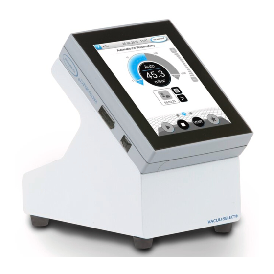
Product description Product description 3.1 VACUU·SELECT vacuum controller ® VACUU·SELECT is a vacuum controller consisting of an ® Description of vacuum controller operating panel and an external vacuum sensor, e. g., the VACUU·SELECT Sensor. ® The controller was developed for applications which require a controlled vacuum. -
Page 22: Product Views
Product description 3.2 Product views 3.2.1 Operating panel The operating panel has a color display with a touchscreen. Depending on the type of installation, the display can be rotated by 90°. Top view + front view Top view Front view Meaning ON/OFF button Cover of USB port, type A*... -
Page 23: Interfaces
Product description 3.2.2 Interfaces Rear view Interfaces at the back Meaning 3x connection sockets for VACUU·BUS components ® Recess for VACUU·SELECT Sensor ® Power supply via VACUU·BUS , plug‑in power supply connec‑ ® tion or vacuum pump/pumping unit Rating plate Option: Spring clip as fixing for built‑in version Stand for desktop version, foldable USB port, type A... - Page 24 Product description Side view Side view Mounted spring clips – fixing for built‑in version Meaning Stand and brace extended for desktop version 20901059_EN_VACUU·SELECT_V1.3_280119...
-
Page 25: Vacuu·select ® Sensor (Optional)
Product description 3.2.3 VACUU·SELECT Sensor (optional) ® The vacuum sensor for this product is mounted externally, e. g., Description of VACUU·SELECT on the controller housing, on the application or in the pumping ® Sensor unit. Communication with the controller takes place via the VACUU·BUS. -
Page 26: Vacuu·bus® Peripheral Devices
® and are used and monitored until the controller is switched off. If a previously connected component is no longer found, the control‑ ler displays an error message. In the case of the VACUU-SELECT , all VACUU-BUS ® ® components can be individually activated or deactivated without disconnecting the plug. -
Page 27: Examples Of Use
Product description 3.4 Examples of use Vacuum concentrator Example Vacuum concen‑ trator PC 3001 VARIO select vacuum pumping unit Meaning VACUU·SELECT operating panel, removable ® VACUU·SELECT Sensor permanently mounted in the pump‑ ® ing unit Exhaust hose (diverted into an exhaust hood) Vacuum hose Example: Cold trap Example: Vacuum concentrator... -
Page 28: Installation And Connection
Installation and connection Installation and connection 4.1 Transport Products from VACUUBRAND are packed in sturdy, recyclable packaging. The original packaging is accurately matched to your product for safe transport. If possible, please keep the original packaging, e. g., for >... - Page 29 Installation and connection NOTE Condensate can damage the electronics. A large temperature difference between the storage location and the installation location can cause condensation. After goods receipt or storage, allow your vacuum device to > > acclimatize for at least 3‑4 hours before initial use. Desktop version If the stand is extended backwards and secured with the brace, Use as desktop...
- Page 30 Installation and connection Installation cut‑out (in control cabinet, lab furniture, cable duct) Cut‑out dimensions Wall thickness Dimensions (a) for installation cut‑out 1 mm 0.04 in. 111.5 mm x 111.5 mm 4.39 in. x 4.39 in. 2 mm 0.08 in. 112 mm x 112 mm 4.41 in.
-
Page 31: Sensor Connection
Installation and connection 4.3 Sensor connection Connect and mount the VACUU·SELECT Sensor ® Mount and Phillips connect the Gr. 2 VACUU·SELECT ® Sensor 1. Pull out the VACUU·BUS plug attachment (a) and insert it ® into (d). 2. Insert the (c) into the VACUU·SELECT Sensor... -
Page 32: Electrical Connection
Installation and connection 4.4 Electrical connection > Lay the connection cable such that it cannot be damaged by IMPORTANT! sharp edges, chemicals, or hot surfaces. Power supply via plug‑in power supply* Plug‑in power supply * Short circuit-proof wide range power supply unit with integrated overload protection and country-spe- cific plug attachments... - Page 33 Installation and connection Connect plug‑in power supply to the controller > Insert the VACUU-BUS cable of the plug‑in power supply ® into the plug‑in connection of the controller. Power supply via plug‑in power supply Connect power supply > Insert the plug‑in power supply into the power outlet. 5 The green LED on the plug‑in power supply lights up.
-
Page 34: Vacuum Connection
Installation and connection 4.5 Vacuum connection WARNING Risk of bursting due to overpressure Prevent uncontrolled overpressure, such as when > > connecting to a locked or blocked tubing system. The vacuum connection is made at the connected vacuum sen‑ sor. The connection can be made in various ways. Connection options Connection Connection via PTFE hose DN 8/10, e.g.,... - Page 35 Installation and connection Connect PTFE hose Required connection material: Union nut M14x1, sealing ring, (a) (b) PTFE hose. 1. Connect the sealing ring (a), the union nut (b) and the PTFE hose (e) as shown. 2. Push the PTFE hose with the union nut into the vacuum con‑ nection of the sensor and tighten the union nut until hand‑...
- Page 36 Installation and connection Sensor connection via small flange Required connection material: VACUU·BUS extension cable for connection to the controller (option), clamping ring with uni‑ versal centering ring or inner centering ring for KF DN 16 (tool: open‑end wrench SW17). 1. Remove the blind plug and place the small flange KF DN 16 (b) on the vacuum connection of the sensor (a).
-
Page 37: Venting Connection (Option)
Installation and connection 4.6 Venting connection (option) DANGER Risk of explosion by venting with air. Depending on the application, venting can cause explo‑ sive mixtures to form or other hazardous situations to arise. Never vent processes with air which could form an >... -
Page 38: User Interface
User interface User interface 5.1 Switch on controller Switch on device > Briefly press the ON/OFF button on the controller 5 The device starts up 5 The process screen is shown Functions of the ON/OFF button ON/OFF Meaning ON/OFF button Switch on controller ` Briefly press ON/OFF button. -
Page 39: Touchscreen
User interface 5.1.1 Touchscreen The controller is a device operated via touchscreen. You can, for Touchscreen operation example, select, start, and stop an application by tapping the dis‑ play. By making various gestures, you can access advanced features: switch between views, edit applications, or use the help and con‑ text features. -
Page 40: Screen Orientation
User interface 5.3 Screen orientation Supported screen orientations Example Landscape and portrait view 0° 90° 180° 90° The following descriptions for operation and function are de‑ IMPORTANT! scribed in vertical format (portrait). The descriptions are also valid for horizontal format (landscape), even though the operat‑... -
Page 41: Display And Operating Elements
User interface 5.4 Display and operating elements The display and operating elements of the controller are summa‑ rized and explained in this chapter. > Refer to this chapter if you want to read about the meaning of a display or an operating element during operation. 5.4.1 Process screen (main screen) After the device is switched on, the process screen appears. -
Page 42: Display Elements
User interface 5.4.2 Display elements Status bar Color Meaning Status bar color codes Standard Gray Yellow Warning Error Sounds Sound Meaning Sounds Touch tone unless muted ` Feedback entry Warning or error ` Shows that an error or warning is present. ` Active while error status persists. - Page 43 User interface Pop‑up windows (context menus) Graphic Function Examples Numeric keypad with special buttons Pop‑up window ` Enter numerical values. ` Select a function using special buttons (OFF, ATM, AUTO). ` Min./max. values displayed. ` Values outside the permissible input range are not accepted.
-
Page 44: Operating Elements And Symbols
User interface 5.4.3 Operating elements and symbols Status bar Symbol (icon) Meaning Access help ` Tips for operation can be accessed from any menu level. USB connected ` Shows that a device is connected via USB. (option) WiFi active Example ` Shows that a WiFi USB dongle is inserted. - Page 45 User interface Operating elements – process steps Button or icon Meaning Application icon Active Locked ` Tap briefly to open the parameter list. ` Press and hold to open the context menu. Shortcut ` Open the applications menu. Right/left arrow Process screen ` Open/close the process step display.
- Page 46 User interface Input field or selection field Parameter list ` Tap to open a pop‑up window where you can enter values or select a function, even during operation. Blue Input field for active process Input field for inactive process Black Operating elements for control Button Function Active...
-
Page 47: Operation
Operation Operation The controller has an application‑based user interface. You can select, edit and start an application from a series of pre‑defined basic applications. Fine adjustments for the selected application can be made at any time in the parameter list or directly via the 5.4.3 Operating elements and symbols on page 6.1 Applications 6.1.1 Select and start application... -
Page 48: Adjust Pressure Setpoint
Operation 6.1.2 Adjust pressure setpoint The controller offers a variety of options for adjusting the pres‑ sure setpoint during operation. Change pressure setpoint in the parameter list Tap/press lightly > Enter a target value in the pop‑up and confirm the entry Fine adjustment via step buttons ‑... - Page 49 Operation Adjust pressure setpoint using marker Hold down and drag Release Adjust pressure setpoint in digital pressure display Tap/press lightly > Enter a target value in the pop‑up and confirm the entry. 20901059_EN_VACUU·SELECT_V1.3_280119...
-
Page 50: Venting
Operation 6.1.3 Venting Vent briefly Brief venting > Tap/press lightly Slight pressure increase. Vacuum control running. Vent to atmospheric pressure Continuous venting > Hold down Vacuum control stops. ~ 3 sec Pressure increase until atmospheric pressure is reached. 20901059_EN_VACUU·SELECT_V1.3_280119... -
Page 51: Stop Application
Operation 6.1.4 Stop application Stop application > Tap/press lightly Vacuum control stops. 6.2 Application parameters (parameter list) In the parameter list, you can individually change and adapt vari‑ ous process‑related values before and during operation. Adjust parameter Example Adjust motor speed 1. - Page 52 Operation Example Adjust motor speed parameter 3. Enter the required motor 4. Confirm entry. speed in the pop‑up. Cancel Confirm Tap/press lightly 5. Confirm the change in the Once the application starts, parameter list. the motor runs at the adjusted speed.
-
Page 53: Pressure Graph
Operation 6.3 Pressure graph The pressure graph is on the same level as the process screen. The menu shows pressure curves of measured vacuum values. The pressure curve is shown until a new application is started, at which point it is replotted. View pressure curve ... -
Page 54: Main Menu
Operation 6.4 Main menu The main menu is on the same level as the process screen. The submenus of the controller can be accessed from the main menu. View main menu > Example View main menu Swipe right >... -
Page 55: Applications
Operation 6.4.1 Applications This menu lists all applications: default application, favorites, and newly created applications. View application menu View applications > submenu Tap/press lightly Display the applications submenu. Show context menu Example > View context menu ~ 3 sec for applications Hold down The context menu... -
Page 56: Favorites
Operation 6.4.2 Favorites Applications marked as favorites are identified by a star on the button. Add favorites Example Add favorites ~ 3 sec Hold down Tap/press lightly Confirm Text changed in the con‑ Button with favorites star. text menu. -
Page 57: Main Menu
Main menu Main menu 7.1 Advanced operation 7.1.1 Application editor In the application editor, you can compile your own application using the building‑block principle and save it with an appropriate name. Existing applications can be used in the application editor as tem‑ plates, and then saved with a new name. -
Page 58: Menu Bar And Description
Main menu Application editor display > Tool tips help Hold vacuum when selecting process steps. Menu bar Overview of process steps Building blocks with individual process steps which you can scroll through and select as required. 7.1.2 Menu bar and description Menu bar Icon buttons Meaning... -
Page 59: Overview Of Process Steps
Main menu Description of the application New application: this name is automatically changed as soon as you give your application an appropriate name using Save as. Description of the new application: here, you can enter a brief Example: description of your application. This description appears later in Application editor the parameter list. -
Page 60: Process End
Main menu The process step sections are numbered from top to bottom, from 1 to n. If a process step section is added, shifted or removed, the numbering is adjusted automatically. 7.1.4 Process end Process end means the defined end of an application. Process steps can only be placed above this. -
Page 61: Edit Application
Main menu 7.1.5 Edit application Create a new application Example Create a new application Tap/press lightly Hold down and drag Release Save as Confirm Exit menu 20901059_EN_VACUU·SELECT_V1.3_280119... - Page 62 Main menu Example Edit new application Tap/press lightly Hold down Save Confirm Exit menu New application listed with white symbol in applications submenu. 20901059_EN_VACUU·SELECT_V1.3_280119...
-
Page 63: Remove Process Step
Main menu 7.1.6 Remove process step Change application Example Edit existing application Hold down Tap/press lightly Hold down and drag Release Save Exit menu The removed process step is no longer displayed in the parameter list of the application. 20901059_EN_VACUU·SELECT_V1.3_280119... -
Page 64: Settings
Main menu 7.1.7 Settings In this submenu you can adjust the display, switch to another language, and make presettings for connected VACUU·BUS pe‑ ripheral devices. View settings submenu Example > Main menu \ Settings \ Basic settings Tap/press lightly Meaning of the context menu Under Display, you can change... - Page 65 Main menu You can specify presettings for your Example process in Basic Settings. The Overview vacuum sensor, which measures Context menu actual pressure, is shown here. settings Meaning of basic settings Function Setting Meaning Overview of possible basic Autostart Off / On Off: The controller is set to settings...
-
Page 66: Settings/Administration
Main menu 7.1.8 Settings/administration Administration area of the controller – only for authorized staff. View administration submenu Example Main menu \ Settings \ Adminis‑ tration Tap/press lightly Submenu with buttons for administrative purposes. Meaning of the context menu Adjustments for date and time. - Page 67 Main menu Presettings for adding the controller to your network. Activate command for loading soft‑ ware update from connected USB flash drive. Reset the controller to the factory settings. IMPORTANT! Restoring the factory settings deletes all data, settings and ap‑ plications.
-
Page 68: Administration - Import/Export
Main menu 7.1.9 Administration – import/export View import/export submenu Example > Main menu \ Settings \ Adminis‑ tration \ Import/ Export Tap/press lightly Meaning of the context menu You can use the export function to Example transfer data, such as applications Overview you have created, to other control‑... -
Page 69: Administration - Vacuu·bus
Main menu 7.1.10 Administration – VACUU·BUS The VACUU·BUS submenu simplifies the detection and manage‑ ment of VACUU·BUS components. View VACUU·BUS submenu Example > Main menu \ Settings \ Administration \ VACUU·BUS Tap/press lightly The buttons retrieve context menus. The context menus facilitate the use of presettings for VACUU·BUS components, e.g., address configuration, detection of connected components. - Page 70 Main menu Using component activation, con‑ nected VACUU·BUS components can be individually activated or de‑ activated, i.e., the components can remain connected but are switched on or off at the controller as re‑ quired for the ongoing process. Pop‑up for the calibration of con‑ nected vacuum sensors at ambi‑...
-
Page 71: Data Logger
Main menu 7.2 Data logger View data logger submenu Example > Main menu \ Data logger Tap/press lightly Meaning of the context menu In the data logger settings, the Overview storage interval and download peri‑ Context menus od can be specified. Data logger If a USB flash drive is connected, Cancel... -
Page 72: Service
Main menu 7.3 Service In this menu, you can find or download information about the de‑ vice. In the event of an error, please forward this information to our Service Department. View service submenu Example > Main menu \ Service Tap/press lightly Meaning of the context menu... -
Page 73: Troubleshooting
Sound Meaning Warning or error ` Shows that an error or warning is present. ` Active while error status persists. 1 -> Phone: +49 9342 808-5660, fax: +49 9342 808-5555, service@vacuubrand.com 20901059_EN_VACUU·SELECT_V1.3_280119... -
Page 74: Acknowledge Error Indication
Troubleshooting 8.1.2 Acknowledge error indication Errors must be acknowledged after the fault has been remedied. Error information and acknowledgement View message Acknowl‑ edge Tap/press lightly Error message reset. 8.1.3 Error indication PC 520/PC 620 Warning Error Tap/press lightly Warnings and / or errors are indicated by a flashing pressure curve. If the flashing pressure curve is pressed, the process with fault can be called up. -
Page 75: Error - Cause - Remedy
Troubleshooting 8.2 Error – Cause – Remedy 8.2.1 Pop‑up message Error ` Possible cause Remedy Personnel Error – Cause – Remedy Specialist Communica‑ One or more Deactivate relevant VACUU·BUS compo‑ VACUU·BUS com‑ tion error nents were removed. ponents. Perform component ... -
Page 76: General Faults
Troubleshooting Error ` Possible cause Remedy Personnel Operator Maximum liq‑ Full status indicator Empty the glass of a level sensor. flask or container in uid level question. reached Level sensor discon‑ nected. Connect level sen‑ sor. Level sensor not adjusted correctly. - Page 77 Troubleshooting Error ` Possible cause Remedy Personnel Specialist Transfer failed No USB flash drive Connect a USB connected. flash drive with sufficient storage Not enough storage space. space on the USB flash drive. Specialist Venting valve No voltage applied. Check VACUU·BUS ...
-
Page 78: Device Fuse
Troubleshooting 8.3 Device fuse There is a device fuse, type: Nano fuse 4 A/t, on the circuit board of the controller. If blown, the fuse can be replaced under ESD conditions after the cause has been remedied. NOTE Damage possible if work is performed incorrectly. Have maintenance work performed by a trained electrician >... - Page 79 Troubleshooting Change device fuse 2. Carefully lift the display. 3. Carefully pivot back the display. 4. Lever the fuse out of the base. 5. Insert the new fuse into the base. 6. Close the housing tightly. 7. Tighten the housing screws with the Torx screwdriver;...
-
Page 80: Appendix
Appendix Appendix 9.1 Technical information Type Vacuum controller VACUU·SELECT ® 9.1.1 Technical data Ambient conditions Technical data (US) Working temperature 10‑40 °C 50–104 °F Storage/transport tempera‑ ‑10‑60 °C 14‑140 °F ture Max. altitude 2000 m 6562 ft above sea level above sea level Protection class (front) IP 20... -
Page 81: Rating Plate
Appendix Dimensions (mm) Dimensions VACUU·BUS cable 9.1.2 Rating plate In the event of an error, make a note of the type and serial > > number on the rating plate. When contacting our Service Department, please provide > > the type and serial number from the rating plate. This will allow us to provide you with specific support and advice for your device. -
Page 82: Sensor (Optional)
Appendix 9.1.3 VACUU·SELECT Sensor (optional) ® Wetted materials Wetted materials Component Wetted materials Sensor Aluminum oxide ceramic, gold‑coated (if applicable) Measurement chamber Small flange Sealing ring at the sensor Chemically resistant fluoroelastomer O‑ring inside small flange Hose nozzle Venting valve seal FFKM Optional: blind plugs without Epoxy resin... -
Page 83: Ordering Information
Appendix 9.2 Ordering information Vacuum controller Ordering information Order no. VACUU·SELECT with power supply unit, with sensor ® 20700000 VACUU·SELECT without power sup‑ ® 20700040 ply unit, without sensor VACUU·SELECT with power sup‑ ® 20700050 ply unit, without sensor Accessories Order no. -
Page 84: License And Privacy Information
Instructions for use 20901057 Sources of supply Purchase original accessories and original spare parts from a International subsidiary of VACUUBRAND GMBH + CO KG or your local dis‑ sales offices and distribution tributor. Information about our complete product range is available >... -
Page 85: Service
Appendix 9.4 Service Take advantage of the comprehensive range of servic‑ Service offer and es available from VACUUBRAND GMBH + CO KG. service range Services in detail Product consultation and practical solutions ƒ Fast delivery of spare parts and accessories ƒ... -
Page 86: Index
Appendix 9.5 Index Index Abbreviations ........12 Icons ..........10 Action steps ........11 Import/export ........68 Add favorites........56 Improper use ......14, 15 Additional symbols......10 Instruction modules ......8 Adjust motor speed..... 51, 52 Adjust parameter ......52 Landscape ........ - Page 87 Appendix Safety ..........7 Safety information......14 Screen orientations......40 Select application ......47 Service..........72 Service handling ....... 85 service range ........85 Side view .......... 24 Sounds ..........42 Sources of supply ......84 Standard pressure display ....42 Start application ........
-
Page 88: Eu Declaration Of Conformity
EC Declaration of Conformity Déclaration CE de conformité Hersteller / Manufacturer / Fabricant: VACUUBRAND GMBH + CO KG · Alfred‑Zippe‑Str. 4 · 97877 Wertheim · Germany Hiermit erklärt der Hersteller, dass das Gerät konform ist mit den Bestimmungen der Richtlinien:... - Page 89 20901059_EN_VACUU·SELECT_V1.3_280119...
- Page 90 20901059_EN_VACUU·SELECT_V1.3_280119...
- Page 91 20901059_EN_VACUU·SELECT_V1.3_280119...
- Page 92 Technology for Vacuum Systems Manufacturer: VACUUBRAND GMBH + CO KG Alfred‑Zippe‑Str. 4 97877 Wertheim GERMANY Phone: ƒ Head office +49 9342 808‑0 ƒ Sales +49 9342 808‑5550 ƒ Service +49 9342 808‑5660 Fax: +49 9342 808‑5555 Email: info@vacuubrand.com Web: www.vacuubrand.com...
Need help?
Do you have a question about the VACUU-SELECT and is the answer not in the manual?
Questions and answers